International Journal of Innovative Technology and Exploring Engineering (IJITEE) ISSN: 2278-3075, Volume-8, Issue- 6S4, April 2019
Abstract—This paper elucidates a multi cell rectifier for AC to DC for single-phase energy transformation which is obtained by exclusive converter circuits to generate high frequency using the passive components for alternating to direct current. The anticipated method hires an easy structure based on concept of pulse modulation. An effective optimization scheme is exploited to enhance the filter constraints. A converter using power electronic switches will generate the harmonics. Harmonics will reduce the system stability. The harmonics reduced by using LLCL filter structure will enhance the stability of the power system network. The comparsion of LCL and LLCL filter is made with the help of THD analysis.
Keywords — Passive filter, Harmonics, Stability
I. INTRODUCTION
Multi cell converters are picking up temptations for
modern power transmission networks and systems these days because of their promising points of interest. The advantages accessible by such rectifiers contrasted with its single cell partner stay investigated by numerous companies have decreased the heat losses and reduced interference in electromagnetic fields. Owing towards the previously revealed advantages, this methodology is additionally considered as one of the alluring choices to single cell rectifier including energy transformation in fixed line applications, power distribution system applications and other influence semiconductor uses.
In the sphere of electro technics (static machines, spinning mills, transmission and distribution), dealing with power industries charges indicates the utilization of various voltage altitudes depending on the energy to be taken. The basic discussion off that ruled such decisions can be rearranged as chases: generally speaking overall financial cost is essentially an aggregate ofcircuit breaker cost, towercost and conduction losses, whereas effectiveness isobtained as a proportion involving the above discussed elements. (The criteria for the voltage levels get vary slightly from state to state, but the common rule is if we use high power, voltage will also be higher. For instance, multi megawatts processes normally will have voltage greater than 1 kV and the increase of electrical power in any application will raise the voltage to 24V or 48 V.
The least difficult and customary solution for this problem is to utilize a first order inductor filter. The essential tactic for this inductance filter is to agree harmonic analysis which is the most extreme allowable THD (<5%). Despite the fact that, the L-filters are invaluable regarding
Revised Manuscript Received on April 12, 2019.
R.Suganya, Senior Assistant professor, IFET College of Engineering, Villupuram, Tamil Nadu, India.(E-mail: [email protected])
B.Balaji, Assistant Professor, IFET College of Engineering, Villupuram, Tamil Nadu, India.(E-mail: [email protected])
straightforwardness, they have a few downsides, for example, cumbersome size, wastefulness and poor elements. LLCL-filters, then again offer predominant harmonic constriction, however it might add to the instability of the power system network. Accordingly, damping must be incorporated into the control plan to pledge the greatest probable capacity of the controller. A portion of the design methodologies of LLCL channels are featured.
Despite the fact that, it appears that the situation using the dimension of the inductance filter can be diverse if there should arise an occurrence of CHB converters contrasted with single cell converter, the upsides of utilizing LLCL can even now be substantial for such rectifiers as talked about. In this paper, a patent recorded multi cell rectifier topology with sinusoidal modulation is explained. The implemented strategy can diminish the absolute dimension of the inductor contrasted with the inductance filter based rectifier for a particular amount of rectifier cells.
In accumulation to that, the highlighted strategy is additionally fit for diminishing the quantity of singular modulated signals necessary to be contrasted with rectifier and along these lines gives a savvy controller arrangement. A deliberate plan strategy for the inductive filter and constraint depicted is dependent on only the calculation made in the discussion. The commitment of this effort is to demonstrate the advancement of another single stage multi cell rectifier strategy with pulse technology.
II. SOLID STATE SWITCHES
In this paper, semiconducting devices like semiconductor diode, transistor, FET, MOSFET, Insulated gate bipolar junction transistor with their V-I characteristics is discussed. In solid state electronics circuitry, these semiconductor devices will turn in to saturation mode and graft in linear region in the older circuits such as in voltage regulator circuits and fixed regulators. This will creates the devices extremely competent since there are minor damages during the energy transformation.
A. LCL FILTER
The inverter used in the power system network will convert the available input energy to output with high quality and is returned to the power system network when there is an interface between generation and distribution. While interfacing a passive real time filter is very much essential between generation and distribution.
Compressional of LLCL Filter and LCL
Filter using Single-Phase Multi-Cell AC-DC
Converter
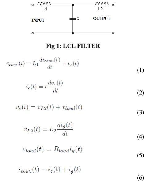
In the grid-connected inverter, a filter is necessary for the interface between the inverter and the power grid. The representation of LCL filter is shown in the figure 1. When comparing with the inductive type filter, the inductive capacitive inductance filter is deliberated to be a desired choice for its effective tempering of interchanging unwanted frequency in the injected network system. The voltage and current equations are represented in equation 1 to 6.
Fig 1: LCL FILTER
(1)
(2)
(3)
(4)
(5)
(6) In order to construct an operative inductive capacitive inductor filter, it is essential to ensure mathematical analysis of the passive filter. In this paper, modeling of the passive filters, designing analysis and observations of the damping requirements of the filter will be systematically discussed.
The goal of the paper is to direct an extensive exploration and demonstrating of the three-stage inductive capacitive inductor filter for not moving separated inverters, equitable for wind vitality or solarapplications.
B. LLCL FILTER
The LLC mesh has just materialized into network linked rectifiers due to its smaller physical size of the filter and better filtering ability. A power system network with the implemented filter coupled with the multi cell rectifier has the similar amplitude characteristic when compared with the traditional filter. Also the frequency of power system network with multi cell rectifiers will respond to the overall system impedance which may affect the stability of the power system network. The representation of LCL filter is shown in the figure 2.
This paper proposes another parameter plan strategy for LLCL filter for the tenacity of strength and vigor of the general network arrangement, when the network control is utilized. In light of this plan strategy, the network can be secure without damping and furthermore strong to the
network parameters variety. The switching and resonant frequencies are represented from equation 7 to 9.
(7)
(8)
[image:2.595.346.498.552.633.2](9)
Fig 2:LLCL FILTER
Also the harmonic low pass filter which is also known as LLCL filter is flattering gorgeous for industrial oriented solicitations. When matched to the LCL filter, an inductance is added with the capacitor, which comprises an Lf–Cf used
in the circuit at the swapping frequency to remove the unwanted frequency component.
III. BLOCK DIAGRAM
A. LCL FILTER
Power is taken from the ac source and fed through the LCL filter circuit. It uses the passive filter which is used to quash the harmonics in the present signal. The harmonics will be produced for the switching operation ON and OFF. The harmonics level will be used for the distorting the unwanted frequency. The productivity of the above said filter fed to the single phase multi-cell AC-DC converters will convert the AC supply into DC supply using IGBT module. The block diagram for LCL and LLCL filter is shown in the figure 3 and figure 4.
Fig: 3 LCL FILTER BLOCK DIAGRAM
International Journal of Innovative Technology and Exploring Engineering (IJITEE) ISSN: 2278-3075, Volume-8, Issue- 6S4, April 2019
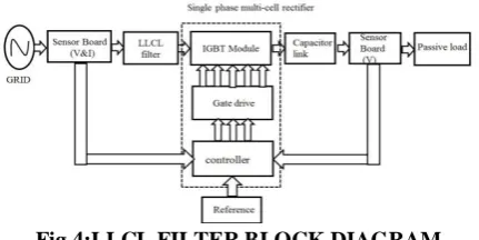
B. LLCL FILTER BLOCK DIAGRAM
[image:3.595.61.277.271.379.2]The variable quantities are retained affiliated by the control circuit such that the variable quantity should be matched which maintains unity power factor.The sensor board will sense the voltage and current from the grid and pass to the LLCL filter which is then given to the IGBT module. The controller output is given to the gate drive circuit which is then send to the power semiconductor module. The base current is created such that active power conversion will take place. The output of the capacitor response mesh then provides the base voltage which is essential for the rectifier module. The interior response loop will form a transfer function which involves a gain factor with sufficient amplitude (K). The output side of DC link capacitor uses filter circuit. Generally passive loads are used. The total harmonic distortion will be further reduced in LLCL filter.
Fig 4:LLCL FILTER BLOCK DIAGRAM
IV. PULSE WIDTH MODULATION
Pulse-width modulation (PWM) is utilized for monitoring the amplitude of numerical signals so as to regulate components which require power. It basically controls the measure of power, in the point of view of the voltage part that is given to a component by cycling the on-and-off periods of a numerical signal rapidly and comparing the pulse width of the "on" stage or duty cycle. To the component, it will appear as a constant power input having a base value which is the output of the on time of the pulse.
A very commanding assistance of PWM is that power loss is very marginal. With contrast to standard levels, analog potentiometer is used to bound the voltage output by principally blocking the electrical path which will exhaust as heat. Also PWM will essentially turns off the power output. Applications can be used to control DC motors and applied for heating elements.
A. SINUSOIDAL PULSE WIDTH MODULATION
Sinusoidal pulse width modulation” is a method of pulse width inflection used in inverters.An inverter produces a yield of output voltage from an input voltage with the assistance of changing circuits to recreate a sine wave by creating one square pulses of voltage per half cycle. Sinusoidal PWM has been an extremely prominent method employed as a part of AC engine control. This is a system that utilizes a carrier wave which is in the form of a triangle modulated by a sine wave and the purposes of convergence decide the exchanging purposes used in the inverter.
In this paper, we discussed about the pulse width modulation. SPWM, the conventional strategy, shows its
comparative large DC exploitation which can be obtained by analogical circuits.
V. PROPORTIONAL AND INTEGRAL
CONTROLLER
The combination of P and I controller is equivalent to the addition of proportional and integral error signal. Now let us scrutinize proportional controller and integral controller numerically. As we probably am aware in a corresponding and basic controller output is legitimately proportionate to the summation of comparative of error and reconciliation of the error input, composing this numerically we have, Where, Ki, Kp are proportional constant and integral constant
individually. The gain expressions are shown in equation 7 and 8 respectively.
(10)
(11)
VI. SIMULATION DIAGRAM OF PROPOSED
SYSTEM
This deals with the software implementation of our paper. This model includes AC-DC converter connected with single phase passive load. This will be helped to control PI. This block is used for reducing the harmonics BH and improve power factor.
The input side input voltage is 200V AC voltage is used in LLCL filter with multi cell converter which will be used in AC to DC converter. The usage of controller is to give equal output and generate pulse.
Output will be measured in voltage meter or scope. To measure the harmonics in this method, THD analysis is used. The first half cycle conduct switch is s1 and s3 will produce the first half cycle.
The negative half cycle conduct switch is s2 and s4 will produce the positive half cycle in continually. Its output voltage level for the input reference value is same. The dc link capacitor is used an interface between the network system and the output of the converter. The pulse generator will produce the required gate input signal.
Fig 5: PROPOSED SYSTEM SIMULATION DIAGRAM
[image:4.595.57.285.52.419.2]VII. CONROLLER AND PWM BLOCK
Fig 6: CONROLLER BLOCK
The controller and pulse generator block is discussed. The controller used for PI controller will give the input for actual voltage and reference voltage for the input side. It will give the sum of the output for the error signal in the system. PI controller output is given to the pulse generator which will produce the switching pulse. The block diagram for controller and PWM is shown in the figure 6 and 7.
Fig7: PWM BLOCK
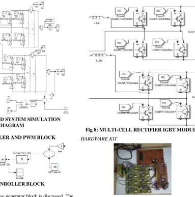
VIII. MULTICELL RECTIFIER IGBT MODULE This block explains the simulation of multi-cell rectifier IGBT module. The input to filter side gives the output. It’s input AC voltage which will convert to DC voltage. The power electronic switch IGBT switch is used in converter circuit for very low switching losses for gate input obtained from the pulse generator. The multi-cell converter in used in the system. The medium voltage high power application is used in this system. The total number of switches used is eight. It is connected in cascade H-bridge method used in the system which is in operation for the given gate pulse input for pulse generator. The multi-cell rectifier module is shown in the figure8.
Fig 8: MULTI-CELL RECTIFIER IGBT MODULE
HARDWARE KIT
IX. COMPARISON OF LCL AND LLCL FILTER
OUTPUT SIMULATION& RESULTS The concept of this work is to reduce the switching harmonics and also to improve the stability of system. To measuring the harmonics level, total harmonics distortion method is used. LCL and LLCL filter circuits are used for reducing the harmonics. The two filters are compared with thesimulation for the output THD level and output voltage in this system.
A. LCL FILTER
[image:4.595.314.536.61.390.2]The below figure 9 shows the LCL filter output used in single phase multi-cell rectifier module expressed as voltage parameter.
International Journal of Innovative Technology and Exploring Engineering (IJITEE) ISSN: 2278-3075, Volume-8, Issue- 6S4, April 2019
[image:5.595.333.520.49.178.2]The output voltage is 120V for the pure output used for dc link capacitor to reduce the oscillations. The below figure 10 shows the AC input current of LCL filter used in single phase multi-cell rectifier module.
[image:5.595.49.552.96.386.2]Fig 10:LCL FILTER USING AC INPUT CURRENT
Fig 11: LCL FILTER THD LEVEL
The LCL filter used in THD level is 9.44% which is measured in FFT analysis using MATLAB is shown in the figure 11.
B. LLCL FILTER
Fig 12: LLCL FILTER USING OUTPUT VOLTAGE
[image:5.595.354.498.420.532.2]Fig 13:LLCL FILTER USING AC INPUT CURRENT
Fig 14:LLCL FILTER THD LEVEL
The LCL filter used in THD level is 3.93% which is measured FFT analysis using MATLAB is shown in the figure 14.
COMPARISON OF RESULTLCL AND LLCL FILTER AC
VOLTAGEINPUT
LCL FILTER CURRENT HARMONIC THD LEVEL
(%)
LLCL FILTER CURRENT HARMONIC THD LEVEL
(%)
200V 9.44 3.93
500V 1.74 1.06
1000V 5.75 0.90
By comparing filter circuits, harmonics is better in LLCL filter circuit. Its level of THD is very low harmonic compared with LCL filter circuit.
X. HARDWARE RESULT
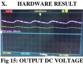
Fig 15: OUTPUT DC VOLTAGE
The above diagram shows the hardware output for the converter topology which is shown in the figure 15 and 16. The CRO is used to measure the voltage in the input of switching frequency of 5kHz. It operates when the output voltage is in high speed switching operation. The pulse required for the sinusoidal pulse width modulation method is used in gate input side.
[image:5.595.79.250.453.560.2] [image:5.595.83.255.591.703.2]The output voltage is a differential rectifier which gets the difference from the input voltages. The first converter is 10V and the second converter is 8V. The converter will operate and will give the output with the help of input reference voltage level. The power rating of converter will be in the range of 100W each converter about 50W.The pulse generated will be given to the micro controller as the pulse power rating is very low and it will amplify the gate signal. Gate circuit is a power amp that receives input power from the PR controller and generates a high input required for IGBT module. The simulation output comparsion is done with the harmonics level for the two filters as discussed above.
XI. CONCLUSION
This paper has proposed the role of the multi-cell AC-DC converter method with filter parameters for single phase. Normally high order harmonics will appear near the switching frequency. Based on this factor, LLCL filter has been proposed. The usage of LLCL filter will attenuate the harmonics and reduce the harmonics which will improve the stability of the power system network which will be suited for medium voltage applications. A comparison is made between using LCL and LLCL filter with the help of total harmonic analysis (THD). By comparing, a small inductor is used with aLf–Cf series resonant network to remove this
unwanted frequency component which improves the stability. The THD level harmonics using LLCL filter get reduced with increase in the voltage. The experimental results shows that THD level for LLCLfilter is 3.93% when compared with LCL filter is 9.44% which shows the reduction in the harmonics. The experimental results and simulation shows the possibility of regulating the voltage waveform as a converter.
REFERENCES
1. Kazi Saiful Alam, “Single phase multicell AC-DC converter with optimised controller and passive filter parameters”, IEEE transactions on industrial electronics, April 2018.
2. J. J. Nedumgatt; Vijayakumar ; Kirubakarann.A; and Umashankar S; “A Multilevel Inverter with Reduced Number of Switches” Conference on Electrical, Electronics and Computer Science, IEEE 2012.
3. Patricio Cortés, Alan Wilson, Samir Kouro, Jose Rodriguez, Haitham Abu-Rub "Model Predictive Control of Multilevel Cascaded H – Bridge Inverters" IEEE Transactions on Industrial Electronics, Vol. 57, no. 8, August 2010.
4. B.Balaji, J.Barnabas Paul Glady, “Simulation and Fault Diagnosis of Positive output elementary Super Lift Luo Converter”, ARPN Journal of Engineering and Applied Sciences, Volume.10, No.9, May 2015.
5. Ch.Sajan , T.Praveen Kumar , B.Rajashekar , K.Srilatha, “A New Topology for High Level Hybrid Cascaded Multilevel Inverter Motor Drive with Energy Storage and Power Distribution”, IOSR Journal of Electrical and Electronics Engineering, IOSR Journal of Electrical and Electronics Engineering, November 2013.
6. R.Revathy, R.Suganya, R.Preetha, “A Novel Multilevel Inverter with reduced number of switches”, Global Journal of Research Analysis, Volume 7, No. 12, December 2018. 7. S. Essakiappan, H. S. Krishnamoorthy, P. Enjeti, R. S. Balog,
S. Ahmed, “Multilevel medium frequency link inverter for utility scale photovoltaic integration,” IEEE Trans. Power Electron., vol. 30, no. 7, pp. 3674-3684, Jul. 2015.
8. Dayue Duan, Lingyu Ye, Fiona Britton, “A Novel Anionic Inward Rectifier in Native Cardiac Myocytes”, circulation research, Vol.86, No.4, March 2000.
9. N.Kamalakannan, A.Arulvizhi, B.Balaji, “Simulation of diagnosing and protecting the boost converter circuit from open circuit and short circuit switch fault:, International Journal of Advanced Research, Ideas and Innovations in Technology in edition, Vol.3, Issue 01, Jan 2017.