Abstract: Established street lighting systems have certain drawbacks as they are operated manually. If this system is not monitored properly, this may lead to more energy consumption. This system requires proper monitoring and energy management techniques to reduce energy wastage. To diminish this energy wastage, we propose a system which operates automatically and also can be remotely supervised and controlled with virtual switches using GUI. This Wi-Fi enabled system uses ESP32 as both a controller and Wi-Fi module. Here we use low bandwidth, a lightweight protocol like MQ Telemetry Transport protocol for IOT implementation. To reduce cost of the system, all streetlight (Wi-Fi) nodes are connected with a single router using Wi-Fi mesh network. Each node is having ESP32 and various sensors for power measurement & object detection. This system can be controlled automatically based on seasonal data stored in central base station. In streetlight failure condition ESP32 will send a fail signal to base station and base station will intimate maintenance operator through mail. Here base station and each node communicate through cloud. For remotely control and supervision a GUI is developed using HTML and JavaScript.
Index Terms: Wi-Fi, Mesh network, sensors, IOT, cloud, MQTT, SMTP, NTP protocol
I. INTRODUCTION
The established streetlight system brings challenges for administration & maintenance department. This also has numerous issues such as low level of intelligence, poor reliability, high power consumption and so on. To reduce power consumption, conventional lamps like CFL lamps and Halogen lamps are replaced by LED lamps. The power consumed by 8 LED lamps is equals to the power consumed by 4 CFL lamps and a single Halogen Lamp [1]. This is due to LED lamps are more efficient than the conventional lamps (CFL, Halogen). In addition to the power efficiency, LEDs have 5 times more life span than CFL and 10 times more lifespan than Halogen lamps. By replacing CFL and halogen lamps with LEDs we can save energy up to 80% [4]. Daylight hours change from season to season mainly in summer and winter, so the lamps should be turned on based on the sunset time [9]. To improve energy efficiency, we have to develop an automatic system which turns on and turn off the streetlights based on seasonal data [2].
Initially this automation system is developed with wires. Later on, to reduce the cable cost and ease of operation, it is replaced by wireless technology. Now a days ZigBee [3],
Revised Manuscript Received on May 10, 2019
Urvi R Bhagat, Electrical Department, The M.S. University of Baroda, Vadodara, India.
Nikhil S Gujar, Research and Development, Electrical Research and Development Association, Vadodara, India.
Sunil M Patel, Electrical Department, The M.S. University of Baroda, Vadodara, India.
Bluetooth [6], radio frequency [7], Wi-Fi [8] technologies are applied for street lighting system. Bluetooth and ZigBee have some limitations. Bluetooth is a short-range wireless communication protocol with a limited range of 10 meters. ZigBee is used for personal area networking which is more expensive than Wi-Fi. Wi-Fi is based on the IEEE 802.11 standards wireless networking technology and it uses internet protocol-based technology. Wi-Fi enabled devices use WLAN and wireless access points connected to the internet. Wi-Fi works on 2.4 GHz (12cm) UHF and 5 GHz (6cm) SHF ISM radio bands and it covers the range of up to 100m. As compared to physical layer technology, this provides better data security.
To exchange the information between two or more devices without using cables or wires, this uses wireless fidelity (Wi-Fi). In automation system, Wi-Fi is used to send sensor information or control signal data among devices. This creates a wireless communication between devices.
A controller integrated with sensors, actuators and other electronic devices interacts with other devices on internet. This is called „Internet of Things‟ (IoT) [5] [6]. This paper describes the network of streetlight nodes & central base station, communication between them through internet using MQTT protocol [10] [11]. Here cloud acts as a broker between the devices and base station which acts as clients. To connect all streetlights with a single router, router uses wireless mesh network [4]. This topology has more advantages as compared to other network topologies. It uses shorter link because of that it requires less transmit power and it is easy to expand the network without re-installation of the whole setup.
In this proposed system, each streetlight node is having ESP32 controller, voltage sensor, current sensor, PIR sensor. As central base station contains Raspberry pi which is fed with seasonal data, this also acts a server and serves GUI for remote monitoring and for cloud service Adafruit.io is used. In this paper we describe ESP32 node configuration, operation of raspberry pi as central base station and Adafruit cloud operation.
II. DEVICES AND METHODS
The conceptual scheme of the proposed system is shown in fig. 1. It consists of streetlights and a central base station. Central base station is located in a nearby building. This system is easily expandable. Here, central base station and streetlights communicate through cloud. Adafruit.io is used as a cloud service provider.
The streetlights are turned
ON/OFF according to
seasonal data. These
Iot Based Wi-Fi Enabled Streetlight Using
Esp32
seasonal data are stored in central base station. From this central base station controlling (ON/OFF) signals are sent to each streetlight through cloud.
Fig. 1 Schematic diagram of the proposed system
In case of emergency or maintenance, streetlights can be overridden with the help of GUI virtual switch. Central base station also acts as server and serves GUI that provide virtual switch for individual streetlight, status indicator and display power consumed by each streetlight. If any malfunction is detected, the central base station intimates by sending mail to the maintenance operator and can perform corrective actions. This system is traffic adaptive and having dimming feature in every streetlight. After midnight when the traffic density is low, streetlight intensity is reduced to 20% by dimming the streetlight and if passive infrared radiation sensor (PIR) detect any object moving then the light intensity increases to 100% after some time it again reduces to 20%.
A. Streetlight Nodes:
Each streetlight node consists of several modules. They are ESP32, current sensor, voltage sensor, PIR sensor and ZCD circuit as shown in figure 2. The voltage sensor and current sensor are interfaced with ADC pins of ESP32 and passive infrared radiation sensor, zero crossing detector are interfaced with GPIO pin of ESP32. Using current sensor, voltage sensor and ZCD data, power consumption is measured and it is sent into cloud. Accordingly current sensor data, streetlight status ON/OFF are also send to cloud. This power and status data are also displayed on GUI. PIR sensor is used to decide the intensity level of streetlight.
Fig.2 ESP32 with all sensors and converter
1) ESP32 as Controller:
ESP32 is a system on a chip microcontroller with integrated Wi-Fi. It is created and developed by Espressif systems. In this a Tensilica Xtensa LX6 microprocessor and an inbuilt antenna switches and other communication components such as amplifiers, filters etc. are used. It is best suited for Internet of Things applications.
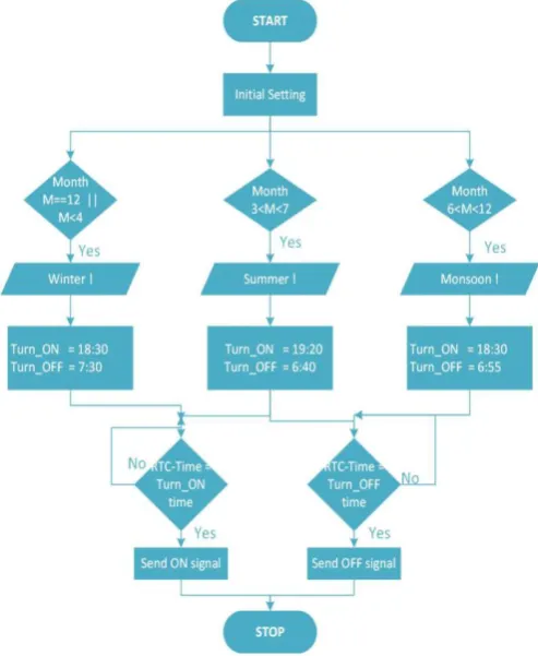
. Fig. 3 shows the flowchart of the software runs on ESP32. This system can be controlled in two ways. One way is according to seasonal data and another way is using virtual switch of GUI.
Whenever the current time matched with seasonal ON time or GUI virtual switch is clicked, streetlight is turned ON. Now the data from sensors and power measured is sent into the cloud. A fault is detected by current sensor reading.
After midnight that is after 12AM PIR sensor reading is checked by controller, according to this reading the intensity of the streetlight is changed. Whenever the current time matches with the seasonal off time, streetlight is turned off. Streetlight can also be turned off forcefully using GUI virtual switch.
2) Presence Sensor:
This sensor is used to identify the presence of a person on road or passage of a vehicle. Placement of this sensor is the main challenge. To avoid any erroneous detection of small animals and to avoid failure to detect children, the sensor should be placed at a perfect height, neither too low nor too high. Here we used PIR sensor, to have good performance and affordable in its price. Detecting range of this sensor is approximately 10 meters with a 120-degree viewing angle. According to the output of this sensor, streetlight intensity is changed, avoiding waste of energy.
3) Power Measurement sensors:
[image:3.595.315.562.164.465.2]In this paper to measure active power, current sensor, voltage sensor and ZCD circuit are used. Here we used PT based voltage sensor and CT based current sensor. Both sensors are operated at 5V and interface with ADC pins of ESP32. ZCD is used for measuring power factor. Zero crossing detector is made using OP-Amp. Fig. 4 show the circuit of ZCD.
Fig. 4 ZCD circuit
The online power consumption information is reported to the cloud. The current sensor is also used to detect the broken-down lamp. The system current is 130mA, so a sensor must be capable to detect this current. To detect the operation of the lamp, an appropriate threshold value has been set between 70 mA and 130mA. As current sensor we used is ZMCT103c and voltage sensor ZMPT101b. Both are suitable for AC and DC current sensing and economical.
B. Central Base station:
Central Base station is the hub of the system. As central base station we use Raspberry Pi 3B+. RaspberryPi3 model B is an ARM based credit card sized minicomputer created by the Raspberry pi foundation. It has a 1.2GHz quadcore cortex A-53 Broadcom BCM2837 64bit ARMv8 processor and
on-board Wi-Fi capability, this central base station sends control signal to the streetlights through cloud according to seasonal data. For that we require real time clock to keep actual time.
Here we stored the seasonal data and run the software that continuously compares real time with ON/OFF time of the seasonal data. To keep actual time, we used NTP protocol instead of RTC. NTP protocol is described below.
Fig. 5 Logic for seasonal data
a) Networking Time Protocol:
This protocol keeps real time without RTC. NTP is used by default on Raspbian and other network devices and computer. This protocol adjusts device clock to match the clock at the server‟s computer. It‟s a client and server-based protocol. NTP client initiates a time exchange request with the NTP server. As a result of this request NTP client is able to calculate the link delay and its local offset. Adjust its local clock to match server‟s computer clock. Almost six exchanges over a period of about 5 to 11 minutes are required to initially set the clock. Transition occurs via the UDP on port 123. NTP uses coordinated universal time UTC to synchronize computer clock with extreme precision.
Fig. 5 shows the logic for the seasonal data. According to the month differentiate the seasons. Set the sunrise and sunset time of each season and compare it with the real time. This software logic is continuously running on raspberry pi.
In failure condition, fail signal is send by ESP32 controller to raspberry pi through cloud. Upon receiving this signal, raspberry pi
b) Simple Mail Transfer Protocol:
SMTP is an internet standard for email transmission. It is a text based, connection oriented, application layer protocol. SMTP is used by mail servers and other mail transfer clients, to send and receive mail on TCP port 25 or 587 or 465. TCP connection on the port (25) to the SMTP server is opened by the client who wants to send the mail and then sends mail across this connection. To communicate between different organizations end to end model is used and for within organization store and forward method is used.
C. Cloud computing:
In this proposed system, Adafruit.io is used as cloud. It is MQTT broker or sever, providing dashboard facility to monitor or control the system. To communicate with this cloud, used MQTT protocol. ESP32 and raspberry pi, both used adafruit.io client libraries, to communicate with this cloud.
ESP32 and Raspberry pi both acts as MQTT client. To connect this with the cloud, use the following information.
Host: io.adafruit.com Port: 1883 or 8883
Username: Username of Adafruit account Password: Adafruit IO key of your account To prevent excessive load on the service, it imposes a rate limit. The rate limit is at most 60 requests within 60 seconds.
1) MQTT protocol:
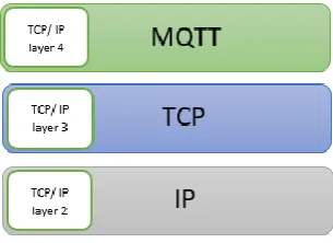
MQ Telemetry transport Protocol is an application layer protocol as shown in fig. 6. It is developed by IBM. Here MQ is a product service name. This protocol is best suited for IoT application, where small sensors data have to send. This is a binary, lightweight, publish/subscribe based messaging protocol for exchange data between clients and server [11].
In this protocol, there are more than one broker and clients. Clients can be either a publisher or a subscriber. Broker is the main heart of this protocol. Here clients communicate through broker only. There is no direct communication between clients. Publisher is the client who want to send data. Subscriber is the one who wants to receive the data.
Publisher send “message + topic name” to the broker. Subscriber subscribe with the topic to the broker. Broker compares the topic. If the topic name is matched then broker forwards publisher‟s message to the subscriber. In this way, MQTT protocol works.
Fig. 6: TCP/IP networking model
MQTT session have four stages:
Connection: TCP/IP connection is established between client and broker using a standard port 1883 or 8883. Here
1883 is used for non- encrypted and 8883 is used for encrypted communication. A CONNECT message is sent by the client to the broker to initiates connections, after the connection broker responds with a CONNACK message.
Verification: For authentication username and password is sent to the broker by the client.
Communication: In this stage, client communicates using PUBLISH/PUBACK for publishing and
SUBSCRIBE/SUBACK for subscribing.
[image:4.595.317.551.199.283.2]Termination: A DISCONNECT message is sent by the client (publisher/subscriber) to broker to terminate the MQTT session.
Fig. 7: MQTT protocol in the proposed system
In this proposed system, ESP32 acts as a publisher, and publish power data, fail signal, status signal with different topics to the adafruit.io as broker. At the same time, it also acts a subscriber to receive control signal from central base station and virtual switch data from adafruit.io.
Raspberry pi also acts as a publisher to publish control signal according to seasonal data and acts as a subscriber for receiving fail signal. For this system, MQTT protocol working is shown in fig. 7
III. RESULTS AND DISCUSSION
[image:4.595.313.544.517.653.2]The design of IoT is based on Wi-Fi enabled streetlight system has been successfully done. 5 Streetlights are installed with this system at ERDA campus, Vadodara. Fig. 8 shows the GUI design of the proposed system. This GUI developed using HTML and JavaScript.
Fig. 8 Graphical User Interface
This system consists of five 30 watts LED streetlights, each connected by a Wi-Fi mesh network. This system can turn ON/OFF remotely using GUI as shown in fig. 8 or central base station.
[image:4.595.97.250.605.716.2]Fig. 9 Streetlight control using virtual switch of dashboard
[image:5.595.60.298.51.213.2]We can also control the intensity of this streetlight according to PIR sensor output. By changing the intensity according to traffic, we can reduce power wastage as shown in fig. 10.
Fig. 10 Intensity control of streetlight
[image:5.595.320.576.216.314.2]In fault condition, if current value goes below threshold value then fail signal is sending by the particular ESP32 and upon receiving this signal by particular ESP32 and up on receiving this signal by the central base station, it sends email to operator. Fig. 11 shows the email receive by the operator when current goes below certain value.
Fig. 11 Email Notification
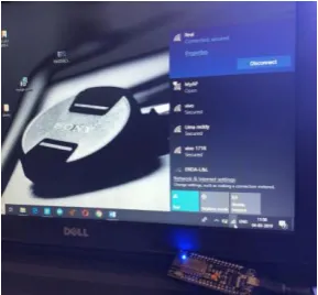
Fig. 12 shows the ESP32 as access point for the mesh network intermediate nodes. These nodes act as a Wi-Fi repeater and extends the router range.
Fig. 12 ESP32 as Wi-Fi repeater
Fig. 13 Final Developed module
Fig. 13 shows the fully functional developed module. This module is erected on the streetlight node.
Power calculations: There are around 37 × 20W LED streetlights present in campus. During manual operation, streetlights are turned ON from 7pm to 7am with 100% intensity.
So, consumed power for one day = 37 × 20W × 12hr = 8880Wh & for one year = 8880Wh × 365 = 3241.2 kWh
After automation, streetlights are turned ON according to seasonal data. From 7 pm to 12am, they are ON with 100% intensity. Then after intensity of streetlights are reduced to 20% till 7 am.
So, consumed power for 7pm to 12am = 37 × 20W × 5hr = 3700Wh and
For 12am to 7am = 37 × 4W × 7hr = 1036 Wh
So, total consumed power per day = 3700 + 1036 = 4736Wh and for one year = 4736Wh × 365 = 1728.64 kWh So, power saving of the system is approximately 46.6 %.
IV. CONCLUSION
In this paper, design of Internet of Things (IOT) based intelligent streetlight controller is discussed. ESP32 is used as a controller as well as Wi-Fi module. In order to provide internet to the other end of campus, Wi-Fi repeaters are made using ESP32 only.
The care has been taken to alert maintenance team about failure of streetlight. An email is generated from the system, to inform maintenance team for taking necessary actions.
The user friendly Graphical User Interface (GUI) is developed to monitor the status of streetlight and also to control it forcefully in case of maintenance.
By making automatic and traffic adaptive system, energy saving from the system is
[image:5.595.55.291.289.395.2] [image:5.595.47.290.500.605.2]Author-1 Photo
Author-3 Photo
REFERENCES
1. D. Sunehra and S. Rajasri, "Automatic street light control system using wireless sensor networks," 2017 IEEE International Conference on Power, Control, Signals and Instrumentation Engineering (ICPCSI), Chennai, 2017, pp. 2915-2919.
2. J. P. Pallo, S. Manzano, D. Chicaiza, C. Nunez, F. Placencia and F. Nunez, "Wireless system for control, monitoring and preventive maintenance of public street lighting," 2018 13th Iberian Conference on Information Systems and Technologies (CISTI), Caceres, 2018, pp. 1-6.
3. F. Leccese, "Remote-Control System of High Efficiency and Intelligent Street Lighting Using a ZigBee Network of Devices and Sensors," in IEEE Transactions on Power Delivery, vol. 28, no. 1, pp. 21-28, Jan. 2013.
4. G. Shahzad, H. Yang, A. W. Ahmad and C. Lee, "Energy-Efficient Intelligent Street Lighting System Using Traffic-Adaptive Control," in IEEE Sensors Journal, vol. 16, no. 13, pp. 5397-5405, July1, 2016.
5. S. M. Patil, M. Vijayalashmi and R. Tapaskar, "IoT based solar energy monitoring system," 2017 International Conference on Energy, Communication, Data Analytics and Soft Computing (ICECDS), Chennai, 2017, pp. 1574-1579.
6. Harshit Satyaseel, Gaurav Sahu, Manisha Agarwal, Jagrity Priya, “Light Intensity Monitoring & Automation of Street Light Control by IOT”, International Journal of Innovations & Advancement in Computer Science IJIACS, Volume 6, Issue 10 October 2017. 7. O. Rudrawar, S. Daga, J. R. Chadha and P. S. Kulkami, "Smart street
lighting system with light intensity control using power electronics," 2018 Technologies for Smart-City Energy Security and Power (ICSESP), Bhubaneswar, 2018, pp. 1-5.
8. B. Kul, "IoT-GSM-based high-efficiency LED street light control system (IoT-SLCS)," 2017 XXVI International Scientific Conference Electronics (ET), Sozopol, 2017, pp. 1-5.
9. S. Biansoongnern and B. Plangklang, "Efficiency improvement of energy management for LED street lightings," 2017 International Electrical Engineering Congress (iEECON), Pattaya, 2017, pp. 1-4. 10. R. K. Kodali and K. S. Mahesh, "A low cost implementation of
MQTT using ESP8266," 2016 2nd International Conference on Contemporary Computing and Informatics (IC3I), Noida, 2016, pp. 404-408.
11. Satyavrat Wagle, “Semantic Data Extraction over MQTT for
IoTcentric Wireless Sensor Networks”, 2016 International Conference on Internet of Things and Applications (IOTA) Maharashtra Institute of Technology, Pune, India 22 Jan - 24 Jan, 2016.
AUTHORSPROFILE
Urvi R Bhagat pursuing M.E. (Microprocessor system and application) from The Maharaja Sayajirao University of Baroda, Gujarat and B.E. (Electronics Engineering) from B.V.M Engineering College, V.V.Nagar, Gujarat.
Nikhil S Gujar Having Experience of more than 10 years in the field of embedded system, power quality measurement and mitigation. Completed M.E. (Microprocessor system and application) from The Maharaja Sayajirao University of Baroda, Gujarat and B.E. (Electronics Engineering) from Shivaji University, Kolhapur, Maharashtra. Published more than 10 international papers including IEEE, CEA-INDIA, CIGRE-Brazil and CIGRE-USA. Established power quality measurement facility for renewable plants (solar and wind) at Electrical Research and Development Association (ERDA), Vadodara, Gujarat.