Low-Thrust Enabled Highly Non-Keplerian Orbits in
Support of Future Mars Exploration
Malcolm Macdonald1 Robert J. McKay2, Massimiliano Vasile2,
Advanced Space Concepts Laboratory, University of Strathclyde, Glasgow G1 1XJ, United Kingdom
Francois Bosquillon de Frescheville3
European Space Operations Centre, European Space Agency, 64293 Darmstadt, Germany
James Biggs2, Colin McInnes4
Advanced Space Concepts Laboratory, University of Strathclyde, Glasgow G1 1XJ, United Kingdom
The technology of high specific impulse propulsion systems with low thrust is improving, opening up numerous possibilities for future missions applying continuous thrust to force a spacecraft out of a natural Keplerian orbit into a displaced non-Keplerian orbit. A systematic analysis is presented as to the applicability of highly non-Keplerian orbits throughout the Solar System. Thereafter, two applications of such orbits in support of future high-value asset exploration of Mars are detailed: a novel concept for an Earth-Mars interplanetary communications relay, on which the paper largely focuses, and a solar storm warning mission. In the former the relay makes use of artificial equilibrium points, allowing a spacecraft to hover above the orbital plane of Mars and thus ensuring communications when the planet is occulted by the Sun with respect to the Earth. The spacecraft’s power requirements and communications band utilized are taken into account to determine the relay architecture. A detailed contingency analysis is considered for recovering the relay after increasing periods of spacecraft propulsion failure, combined with a consideration of how to deploy the relay spacecraft to maximise propellant reserves and mission duration. For such a relay, a combination of solar sail and solar electric propulsion may prove advantageous, but only under specific circumstances of the relay architecture suggested. For highly non-Keplerian orbits the dynamics of the spacecraft is also briefly extended to consider the elliptic restricted three-body problem and the effects of orbit eccentricity.
1
Advanced Space Concepts Laboratory, University of Strathclyde, Glasgow, UK, AIAA Associate Fellow.
2
Advanced Space Concepts Laboratory, University of Strathclyde, Glasgow, UK.
3
Future Studies Operations Concept Engineer, European Space Operations Centre, Human Spaceflight and Exploration Department, Darmstadt, Germany
4
Nomenclature
𝑎𝑟𝑒𝑓 dimensional reference acceleration, equal to unit sail lightness number = 5.93 mms-2
𝒂𝑔𝑐 nondimensional required acceleration vector to balance gravitational and centrifugal force
𝒂𝑆𝐸𝑃 nondimensional acceleration due to SEP thruster
𝑒 eccentricity of orbit of smaller primary in 3-body problem
𝑓 true anomaly 𝐺 gravitational constant 𝐼𝑆𝑃 specific impulse
m spacecraft mass 𝑚1 mass of larger primary 𝑚2 mass of smaller primary 𝒏 thrust vector orientation
p semi-latus rectum of ellipse
𝒓, r position vector with respect to centre of mass of primaries, orbit radius
T continuous and constant low thrust 𝑣 centripetal potential
𝑉 augmented potential 𝛼 pitch angle
𝛽 solar sail lightness number ∆𝑣 change in velocity
∆𝑣𝑒 change in velocity, in ERTBP
𝜆 ratio of 𝒂
to
∇𝑽I. Introduction
he concept of counter-acting gravity, and altering a spacecraft’s trajectory from a natural free-fall path through the use of continuous propulsive thrust, was apparently first proposed by Dusek in 1966 [1] to generate artificial equilibria near the classical Lagrange points. This concept has since become known as a highly non-Keplerian orbit (NKO) and has been extensively studied to establish the fundamental dynamics of the problem [2].
In the late 1970s/early 1980s, Driver [3] outlined one of the first applications of a highlynon-Keplerian orbit. Driver considered a spacecraft that would hover directly above the poles of the Earth for an extended period of time. Such a PoleSitter concept would be enabled by continuous thrust, where the thrust direction was always such that the spacecraft remained at a fixed distance along the polar axis. Subsequently, Forward considered using a solar sail to displace a body north or south of the geostationary ring [4, 5], around a decade after Farquhar had previously considered using a small solar sail to stabilize motion near the classical L1 point in the Earth-Moon system [6]. It is
of note that despite criticism of Forward’s solar sail enabled displaced geostationary orbit concept, it has recently been validated by Baig and McInnes [7].
McInnes collated a significant wealth of material on solar sailing and highly non-Keplerian orbits [8], and the study of solar sail-enabled artificial displaced Lagrange points was considered extensively by NASA/JPL/NOAA under the GeoStorm mission concept [9, 10]. In addition to highly non-Keplerian orbits for solar sails, where the concept was largely developed, large families of orbits are also found to exist for spacecraft equipped with other forms of low-thrust propulsion, such as solar electric propulsion, SEP [2].
Large families of displaced orbits for a generic continuous low-thrust propulsion were first rigorously detailed by McInnes [11, 12], generated by considering the dynamics of the problem in a rotating frame of reference. As the angular velocity of the frame of reference is used as a free parameter of the problem, the orbits can be classified into families defined by the functional form taken by the angular velocity. In particular, the required thrust induced acceleration can be minimized by an optimum selection of the angular velocity.
The initial work led by McInnes has since been studied by others, e.g. Morimoto et al. [13,14], to develop the concept further, as such orbits could have a diverse range of potential applications. However, such work has mainly focused on Earth-centered trajectories - although some authors have considered individual applications of non-Keplerian orbits outside the Earth’s influence. For example, the in-situ observation of Saturn’s rings has been considered by, for example, McInnes [12] and Spilker [15]. In other work, Sawai, Scheeres & Broschart analyzed the control of a spacecraft hovering over a rotating body such as a comet or asteroid [16].Broschart & Scheeres [17] extended this work in the first instance by considering the case of using continuous control thrust to hover above an asteroid, and investigating the stability of realistic hovering control laws in both the body-fixed and inertial
reference frames, as well as presenting a case study of hovering above Asteroid (25143) Itokawa (which was the target of the Hayabusa mission).
In this paper, systematic consideration is given to all the families of non-Keplerian orbits, at a number of bodies in the Solar System to identify new regions of application and interest. Subsequently, the application of highly non-Keplerian orbits in support of future Mars exploration using near to mid-term technology is developed. Two Mars exploration support applications are detailed, where the objective is to outline the underlying astrodynamics, such that detailed mission budgets and timelines are beyond the scope of the paper. These two missions are a Mars communication relay, called The Sojourn Relay, and a solar storm warning mission called AreoStorm. Specifically, the scenarios presented are envisaged to support Mars exploration by high-value assets either in-orbit about Mars, or on the surface, where such high-value assets could be either human or robotic.
II. Highly Non-Keplerian Orbit Model and Definition
Overview
Families of periodic highly non-Keplerian orbits are quite different from open spiral trajectories used for spacecraft orbit transfer. They are obtained by considering the dynamics of the low thrust spacecraft in a rotating frame of reference, where the angular velocity of rotation of the frame of reference is used as a free parameter of the problem. Stationary solutions to the equations of motion are then sought in this rotating frame of reference, which correspond to periodic, displaced orbits when viewed from an inertial frame of reference.
As discussed in [2], trajectories that make use of a continuous thrust to offset gravity can be divided into two categories. The first category is the displacement of 2-body orbits – for example, the displacement of the geostationary ring above the “traditional” ring, which is within the equatorial plane. In this case large families of orbits are found, parameterized by the angular velocity of the rotating frame of reference, and regions of linearly stable orbits can be identified. The second category of displaced orbits is the displacement of 3-body equilibrium solutions. While displaced orbits with a free orbit period may be generated for 2-body systems, a set of artificial equilibrium points are generated for 3-body systems when the angular velocity of rotation of the frame of reference is chosen to be that of the two primary masses. As the region in which the equilibrium solution is sought moves away from the second body in the 3-body problem, the 2 and 3-body problems match asymptotically, with the proviso that the orbit period remains fixed to that of the secondary body.
Model
r2
spacecraft
r1
m2=µ
m1=1-µ µ 1-µ
x y
z
[image:5.612.143.472.74.259.2]a
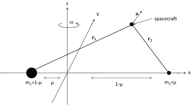
Fig. 1 The rotating coordinate frame and the spacecraft position therein for the restricted three-body problem
With such a system the equations of motion of the spacecraft are given by,
𝒓 + 2𝝎 × 𝒓 + ∇𝑽 = 𝒂
(1)
where, 𝒓 is the position vector of the spacecraft from the primary body, dots denote differentiation with respect to time 𝑡,and 𝑽 and 𝒂 are the augmented potential and the continuous and constant acceleration due to the propulsion
system respectively, the former being given by,
𝑉 = −
1 − 𝜇
𝒓
1+
𝜇
𝒓
2+
1
2
𝝎 × 𝒓
2
(2)
in units where the gravitational constant 𝐺 = 1 and the system has total unit mass, and where 𝜇is the reduced mass,
𝜇 =
𝑚
1𝑚
1+ 𝑚
2(3)
and the latter being given by,
𝒂 =
𝑇
𝑚
𝒏
(4)
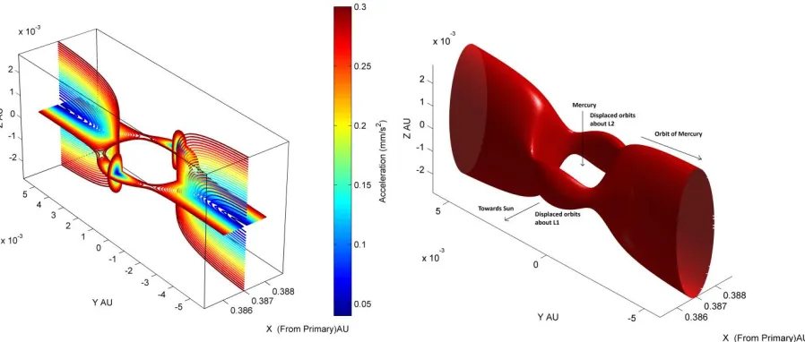
Fig. 2 Artificial equilibrium points for the Sun-Mercury L1/L2 system depicted by equithrust contours
projected onto the planes perpendicular to and parallel to the orbital plane (left), and the equithrust surface equivalent to an acceleration of 0.3mms-2 (right).
The required thrust vector orientation for an equilibrium solution is determined by,
𝒏 =
∇𝑽
∇𝑽
(5)
and the magnitude of the thrust vector, 𝒂 , is given by,
𝒂 = ∇𝑽 .
(6)
With these conditions the spacecraft is then stationary in the rotating frame of reference, tracing out an orbit in the inertial frame. As discussed in [2], Eq. (6) provides a simple definition of what constitutes a highly non-Keplerian orbit. Defining a parameter 𝜆 such that,
𝜆 =
𝒂
∇𝑽
(7)
orbit can be forced to precess at a Sun-synchronous rate, maintaining a science payload permanently within the geomagnetic tail, a concept utilized by the GeoSail mission [20, 21]. An even more recent example is the extended Sun-synchronous orbits proposed by Macdonald et al. [22]. It is worth noting that although these examples are of non-Keplerian orbits, they are a quite separate subset to that of highly non-Keplerian orbits which this paper focuses on.
Extension to solar sail case
Due to the orientation-constrained nature of solar sail propulsion, i.e. a sail cannot thrust towards the Sun, the family of highly non-Keplerian solar sail orbits can thus be thought of as limiting cases of the more general analysis for non-orientation constrained low thrust propulsion technologies discussed in the previous subsection. The simple form of Eq. (4) for the continuous and constant acceleration of the spacecraft is replaced by [23],
𝒂 = 𝛽
1−𝜇𝑟12
𝒓
1∙ 𝒏
2
𝒏
(8)
where, 𝛽 is the sail lightness number, the ratio of solar radiation pressure acceleration to solar gravitational acceleration (fully defined in [8]), 𝒓 1 is the position vector of the spacecraft with respect to the Sun, and 𝒏 is the unit normal to the sail, representing the thrust vector. McInnes [23] then considered the dynamics of the spacecraft in a rotating reference, as shown in Fig. 1. The solar sail lightness number required for equilibrium can be determined to be [23],
𝛽 =
r12 1−μ∇𝑉∙𝒏
𝒓 1∙𝒏 2
.
(9)
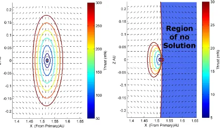
Using these equations the artificial equilibrium points available to a solar sail and a solar electric propulsion spacecraft of equivalent acceleration can be compared, as in Fig. 3; for the purposes of comparison, an SEP spacecraft is considered with acceleration equivalent to a solar sail with characteristic acceleration 0.3 mm s-2.
As can be seen in Fig. 3, the advantage of SEP over the solar sail for this candidate orbit is that there are no forbidden regions (denoted by the filled areas) due to the orientation constrained nature of the solar sail, requiring that it thrusts away from the Sun – meaning that there are areas around both L1 and L2 which are accessible to an
electric propulsion system that are not accessible to a sail. It can also be seen that, even where non-Keplerian orbits are possible with a sail, the region is much smaller as the sail can only bring a component of the acceleration required in the direction of the thrust direction arrows, unlike the SEP system.
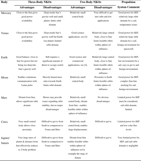
non-Keplerian orbits via both SEP and solar sailing, at various Solar System bodies – a summary of which is given in Table 1.
[image:8.612.81.534.358.621.2]From Table 1 it is seen that highly non-Keplerian orbit opportunities about Earth and Mars offer the best cost – reward ratio from a practical perspective, allowing a usefully large domain of highly non-Keplerian orbits for both SEP and solar sail near-term technologies, whilst providing a sufficiently high photon flux to allow both forms of propulsion to perform well. It is thus prudent to consider applications of highly non-Keplerian orbits about these two bodies in the first instance as further from the Sun there is insufficient photon flux for either the SEP or sail to function particularly well. Bodies closer to the Sun may provide some useful opportunities, but the gravitational potential well is deeper, reducing the size of the orbit domain in a like-for-like comparison for SEP spacecraft. However, it is noted that the close proximity to the Sun delivers a significantly increased solar sail thrust magnitude which can hence offset some of these potential drawbacks. The sail will however need to withstand high film temperatures, and of course the orbit domain is fundamentally limited due to the inability to thrust towards the Sun. Finally, it is noted that the use of a suitable nuclear power source would eliminate many of the power constraint issues detailed in Table 1. However, the system mass could potentially be increased so much by a nuclear reactor as to simply offset any potential gains and equally limiting the acceleration magnitude.
Fig. 3 Non-Keplerian orbit equithrust contours projected onto the plane perpendicular to the orbital plane for the Sun-Mars-spacecraft 3-body system for SEP spacecraft (left) and solar sail (right) of equivalent
Table 1: Potential of non-Keplerian orbits (NKOs) throughout the Solar System
Body Three-Body NKOs Two Body NKOs Propulsion
System Comment Advantages Disadvantages Advantages Disadvantages
Mercury Close to the Sun gives good power availability
Deep inside Sun’s gravity well and small
planet; limits orbit domain
Relatively small central body
Very difficult to get into orbit and few
applications
Good power for SEP, relatively large orbit domain for a sail, temperature issues
Venus Close to the Sun gives good power availability
Deep inside Sun’s gravity well but
Earth-size planet; limited orbit domain
Good science applications; see [2]
Relatively large central body, close to Sun limits feasible orbits
within sphere-of-influence
Good power for SEP, relatively large orbit domain for a sail, benign environment for
spacecraft
Earth Good balance: close to Sun for power but not
being too deep into Sun’s gravity well
Still requires a significant amount of thrust to occupy useful
orbit.
Good science and commercial applications; see [2].
Relatively large central body, close to Sun limits feasible orbits
within sphere-of-influence
Good power for SEP, fair environment for a sail, easy to get to and benign environment
Moon Enables continuous communication with
Lunar poles
Heavily biased mass ratio towards Earth limits orbit domain
Relatively small central body
Proximity to Earth limits feasible orbits
within sphere-of-influence
Good power for SEP, complex Sun-line
tracking for sail, benign environment
Mars Distant from Sun, allows significant orbit
domain
Moons may provide issues regarding orbit stability, but no major
disadvantages
Relatively small central body, distant
from Sun - enables feasible orbits within
sphere-of-influence
No obvious disadvantages
Limited power for SEP must be considered,
sail orbit domain limited
Ceres Very small central body allows close
proximity
Difficult to get to from Earth in comparison to
Venus and Mars
Relatively small central body enables
large displacements
Difficult to get to Limited power for SEP and low solar flux
levels
Jupiter/ Saturn
Very large mass of planet & distance from Sun effectively reduces to 2-body problem
Difficult to get to from Earth in comparison to
Venus and Mars
Distant from Sun enables feasible orbits
within sphere-of-influence at for example the rings of
Saturn
III. A Novel Interplanetary Communications Relay – The Sojourn Relay
A novel application of highly non-Keplerian orbits is for a future Earth-Mars communications relay. This idea is not dissimilar in concept to that proposed for lunar communications by Wawrzyniak & Howell [25], and other authors who have noted that the problem of solar occultation can be avoided using displaced orbits, such as McInnes & Simmons [26], and Simo & McInnes [27], and was introduced briefly in Ref. [24].
An Overview of The Sojourn Relay
For any future high-value asset Mars exploration, such as a human crew or a high-value Unmanned Autonomous System such as an advanced rover or aerial explorer, continuous communication between the surfaces of the two planets will be required. Currently, during periods of solar occultation, assets both in-orbits about Mars and on its surface are out of communication with the terrestrial ground segment. While such a scenario is undesirable for current generation robotic assets, it is acceptable. However, this is not so for human exploration. Therefore, a communication relay is required to ensure continuous communication between Earth and Mars during this period, the new architecture proposed is termed Sojourn to reflect the temporary nature of this driving requirement. To address this issue, non-Keplerian orbits above or below the orbital plane of Mars are suggested as a means of enabling such a relay. Indeed, it is noted that any spacecraft within, or even which passes through, the orbital plane of a planet in the solar system shall experience periods of solar occultation of Earth, and thus the problem is more generic than the specific case of Mars.
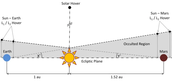
A schematic diagram of the architectural options of such a relay is shown in Fig. 4, where the angle X represents the field-of-view exclusion zone about the Sun as viewed from Earth, and angle Y is the equivalent spacecraft-Mars-Sun angle. The technology requirements of such an array are largely determined by the field-of-view exclusion zone about the Sun, which is dependent on how close to the limb of the Sun radio signals can be transmitted without interference from the solar plasma. For design optimization purposes a spacecraft in proximity of Mars is preferred, as the long slant range back to Earth can be compensated for through the use of a large Earth-based antenna, while a spacecraft in proximity of Earth would require such a large antenna on-board the spacecraft, or on Mars.
1 au 1.52 au
X˚ Y˚
Sun – Mars L1/ L2Hover
Sun – Earth L1/ L2Hover
Solar Hover
Occulted Region
Ecliptic Plane
[image:11.612.137.490.77.247.2]Earth Mars
Fig. 4 Earth-Mars communication relay architecture options out of the orbital plane.
With such an angle the Sun – Mars stations can be determined to be located approximately 0.176AU out of the orbital plane, while the Sun – Earth stations can be determined to be located approximately 0.116AU outside the orbital plane, since the equivalent spacecraft-Mars-Sun angle is then 2.64°. The much shallower gravitational potential well at Mars significantly increases the distance from the planet that a spacecraft can hover in direct comparison to Earth.
An interesting extension to this concept is to consider spacecraft in orbits displaced out of the orbit plane of Mars and either leading or trailing Mars. Considering the symmetry of Fig. 4, the field-of-view exclusion defines a conic region around the Sun where Mars is hidden from the Earth. If this conic region is considered end-on from behind Mars, as shown in Fig. 5, as well as achieving continuous communications by displacing a spacecraft directly above Mars, a spacecraft could also be displaced onto the circular, when projected in two dimensions, region around Mars defined by the field-of-view exclusion, so that one spacecraft was trailing and the other leading the orbit of Mars.
Occulted Region
Spacecraft leading Mars
[image:12.612.206.408.72.213.2]Spacecraft trailing Mars Plane of Mars orbit
Fig. 5 End-on view of an alternative Mars-Earth communication relay architecture option, looking along the orbital plane.
Positioning of the spacecraft then depends on what is required from the mission. The relay spacecraft will need less thrust to maintain their position with respect to Mars if they are not maximally displaced out of the orbital plane, but reducing this displacement increasingly limits communication capabilities to assets near the equator of Mars. To communicate with assets at higher latitudes, particularly the scientifically interesting polar regions, it will be necessary to displace the spacecraft out of the orbital plane.
Relay Using Purely Solar Electric Propulsion
Having outlined the concept of the relay, the amount of thrust required in order to occupy some potential hover points to enable the relay is quantified. To do this a SEP thruster with a maximum thrust of 300mN and a specific impulse (ISP) of 4500 seconds is assumed: these assumptions allow for a consideration of opportunities based on
current or near-term technology, such as the QinetiQ T6 thruster, which will theoretically provide a thrust of up to 230 mN at an ISP of above 4500 seconds for the BepiColombo mission [29]. To provide a benchmark for the study
the spacecraft mass was simply assumed to be 1000kg, thus defining the acceleration capability of the spacecraft to be of up to 0.3 mm s-2.
Fig. 6 An end-on view of NKO depicted by equithrust contours, for a 1000kg SEP spacecraft about Mars, looking along the orbital plane. The outer heavy and inner light circles indicate the field-of-view exclusion
zone for X and Ka-band communications respectively.
As can be seen in Fig. 6 it is much easier to displace the spacecraft orbit from Mars in this plane (i.e. along y) than out of it (i.e. along z) and so a spacecraft can occupy a non-Keplerian orbit on the surface defined by the field-of-view exclusion for less thrust if it trails or leads Mars rather than hovering directly above. For example, displacing the spacecraft 45 degrees out of the orbital plane of Mars would reduce the thrust requirements to approximately 200 mN, assuming the 4 degree field-of-view exclusion defined by X-band communication. So, practically, it may be more feasible to maintain the communications relay using two spacecraft with lower thrust than a single spacecraft which needs higher thrust.
It should also be considered that the non-Keplerian orbit actually need only be maintained during periods of solar occultation, and hence it may be possible to extend the spacecraft lifetime by only using the thrusters to provide significant amounts of thrust during such periods and allowing the spacecraft to follow a conventional near-Keplerian orbit during other periods; hence the name The Sojourn Relay. However, continuous displacement may be attractive to ensure continuous communication with assets at the polar regions at the expense of total mission lifetime. For example, the synodic period of Mars with respect to Earth and the Sun (and thus the occultation repeat period) is approximately 780 days on average, although it varies due to the eccentricity of the orbit of Mars. The actual duration of the communications blackout caused by solar conjunction varies from mission to mission depending on various factors, such as the amount of link margin designed into the communications system, the minimum data rate that is acceptable from a mission standpoint, as well as the exact Sun-Earth-Mars alignment. In addition, the level of solar activity will be a factor, with highly energetic events such as solar flares or coronal mass ejections adding to the general background level of signal disruption - with, conversely, a quiescent Sun during a period of solar minimum activity proving advantageous in such situations. Gangale [31] summarized the communications outage periods for six different recent Mars missions, showing that the average outage period is of the order of one month, although there is a reasonable spread as evidenced by comparison of the approximate 40 days of blackout experienced by the Viking 1 orbiter during the 1976 conjunction and the approximate 18 days of blackout encountered by Mars Global Surveyor in 2004.
Bearing this in mind, it can be envisaged a mission that would see the SEP spacecraft thrusting to hover above Mars for a certain number of days to maintain communications whilst Mars is occulted, and then, when Mars is no longer occulted, using the thruster efficiently to re-acquire the relevant artificial equilibrium point (AEP) via a pre-planned orbital maneuver, returning to the correct point for the next occultation of Mars, where the thruster would then be switched back on to occupy the non-Keplerian orbit position again. Thus, the spacecraft would only need to continually thrust at the levels outlined previously for perhaps only a few weeks in every 2.13-year period (approximately) as opposed to the entire time, which would significantly extend the on-station time as allowed by the thruster propellant reserves.
Finally, it is worth considering the advantages of such a communications relay architecture option, over some of the more obvious potential architectures. Consider a relay consisting of a spacecraft at Earth’s L4/L5 point, or likewise at
Mars’ L4/L5 point. The former case of an Earth-Earth L5-Mars relay then requires that a signal be sent over a total
distance of approximately 3.21AU, with a distance of about 2.21AU between Mars and the relay spacecraft. The latter case of an Earth-Mars L4-Mars relay spans a distance of approximately 3.73AU, with a distance between Mars
As noted by Strizzi et al. [32], the size and power of the equipment needed for these distances make the L4 and L5
locations unrealistic for relay stations, although the inherent stability of these regions is beneficial in terms of station-keeping.
Relay Using Hybrid Solar Electric Propulsion / Solar Sail
Both SEP and solar sail low thrust propulsion systems have their own advantages and disadvantages. Solar sailing has the advantage that it requires no propellant, and thus can maintain continuous low thrust indefinitely, although in practice, long-term degradation of the optical surface may reduce the efficiency of the sail and propellant may be required for attitude control [33]. However, with SEP the thrust can be oriented in any direction, allowing access to artificial equilibria that a solar sail would be forbidden from with its inherent inability to thrust in the direction towards the Sun. Thus, in principle there is a strong case for studying a device that would combine the best features of both systems, to obtain a hybrid sail. Indeed, it has recently been suggested that such an approach may, in recognition of the high Advancement Degree of Difficulty of solar sailing, that is to say the difficulty of progressing solar sailing from one technology readiness level to the next, be the best means of advancing solar sail technology [34]. Such a propulsion concept has been considered in the literature previously, see, for example Leipold & Götz [35] and Mengali & Quarta [36], with the latter showing that hybrid sails have the attractive feature of reducing mission times for heliocentric transfers when compared to both the equivalent pure sail and pure SEP trajectories. Recently, Baig & McInnes [37], Simo & McInnes [27] and Ceriotti & McInnes [38] have all considered the case of displaced highly non-Keplerian orbits for a hybrid sail in the Sun-Earth and Earth-Moon 3-body systems for observation and communications applications.
The analysis of [37] is followed by considering a partially reflecting hybrid sail consisting of an SEP thruster attached to the centre of a solar sail, a model adapted from that of Leipold & Götz [35]. The solar sail is taken to be square, with part of the sail area at the centre of the sail covered by flexible thin film solar cells (TFSC), which act as a power source for the SEP system.
The acceleration vector 𝒂𝑔𝑐 required to cancel the gravitational acceleration of the two primary masses and the centripetal acceleration in the rotating reference frame, allowing an artificial equilibrium point 𝒓𝟎 to be occupied, can be achieved with a hybrid sail through the vector sum of the solar radiation pressure and SEP acceleration vectors. The combination of acceleration from both solar sail and SEP can be thought of as modifying Eq. (6), giving,
∇𝑉 𝒓
𝟎= 𝒂
𝑆+ 𝒂
𝑆𝐸𝑃≜ 𝒂
𝑔𝑐. (10)
instead it is assumed that the thrust from the SEP system is initially used to achieve all of the vector 𝒂𝑔𝑐, allowing the spacecraft to occupy a given artificial equilibrium point. Then, added to that is the magnitude of the acceleration from the solar sail oriented such as to maximize thrust along the vector 𝒂𝑔𝑐, as now defined at the displaced AEP. This allows an examination to be performed as to the potential gains of adding a solar sail to a SEP spacecraft, rather than vice-versa, and recognizes the relative technical maturity of the two technologies. It should hence be stated that such a hybrid is not an exact like-for-like comparison with the hybrid of Baig & McInnes, as by definition the approach taken in this paper has greater acceleration available to it, and to truly compare the performances of the two an equal mass budget would have to be defined for each spacecraft. Likewise, in regions where the solar sail is effective, the hybrid has a greater magnitude of acceleration available to it compared to the pure-SEP system, allowing access to AEP that would otherwise be beyond the capabilities of the pure SEP system with thrust equal to that of the SEP part of the hybrid SEP/solar sail spacecraft, but again the comparison is inexact unless spacecraft of equal mass are compared.
With this in mind the analysis considered for a pure-SEP system, in determining the non-Keplerian orbit equithrust contours at Mars, can be repeated for the hybrid sail. In this analysis it is assumed that the hybrid spacecraft has a solar sail of characteristic acceleration 0.2 mms-2 (equivalently, sail lightness number of 0.034) and sail reflectivity 0.9, the sail area is thus 45m × 45m, giving a sail loading of 45.63 gm-2
. The TFSC reflectivity is taken to be 0.4 and the TFSC area is 12 m2. This sail is assumed to be attached to a 1000 kg SEP-propelled spacecraft capable of a maximum thrust of 300mN, as assumed previously. It is found that adding a solar sail to the SEP spacecraft allows access to a greater volume of space for non-Keplerian orbits: specifically, there is a reasonably large increase of available non-Keplerian orbits on the day-side of the planet around L1 and a small increase on the night-side of the
planet around L2. This asymmetry is to be expected, given the regions of non-Keplerian orbits the pure sail can
access. It is also found that the addition of the solar sail does not allow the hybrid to be displaced any further out of the orbital plane for the same amount of thrust, and thus in the context of the Earth-Mars communication relay as described previously this is perhaps a disappointing result. However, deeper consideration of the solar sail reveals why both of these points are indeed the case.
is no advantage in using a hybrid to hover directly above Mars does not in itself rule out the possibility of a hybrid system being potentially more useful than SEP alone as part of such a communications relay. Hovering directly above Mars is not exactly the same as a polesitter spacecraft, i.e. a spacecraft constantly aligned with the polar axis, due to the tilt of that axis, as illustrated in Fig. 7 for the 25.2 deg. axial tilt of Mars. Four specific points of interest are highlighted in Fig. 7 which illustrate where the spacecraft can be stationed such that they are directly above the pole of Mars.
[image:17.612.67.539.331.620.2]Three of these points are on the day-side of Mars: the first two points show that the addition of the solar sail component of the hybrid extends the distance the spacecraft can hover directly above the pole at the summer solstice from 0.114AU to 0.137AU (i.e. can now station at the former point as opposed to the latter), or, equivalently, to occupy the latter point the hybrid spacecraft needs a thrust of only 240mN from the SEP component, compared to the 300mN required for a pure-SEP spacecraft. The third point shows the minimum distance required to complete the communications relay in Ka-band, which requires approximately 130mN from the hybrid SEP and 190mN from the pure-SEP. The fourth point on the night-side of the planet shows that having the sail is of no additional benefit here.
Fig. 7 NKO equithrust contours at Mars, projected onto the plane perpendicular to the orbital plane, for a hybrid sail. The ± 25.2 deg. lines are the angles of the polar axis of Mars, denoted by dashed lines, with respect to the normal to the orbital plane at the summer and winter solstices respectively. The two
Thus, it can be seen that the addition of the sail can reduce the SEP requirements to hover directly above the pole of Mars at the summer solstice, or, equivalently, allow the spacecraft to hover higher than previously possible without the sail. Clearly, in this case it would only make sense to do this over the day-side of the planet, with this region being where the sail is most effective: the volume of space within which equilibria are possible on the night-side of the Earth is severely constrained with a realistic solar sail. This argument is effectively analogous to that made by Ceriotti and McInnes, who determined families of optimal periodic polesitter orbits above Earth that minimized the SEP propellant consumption over a 1-year period [38], and showed that these optimal orbits are displaced less far out of the orbital plane when on the night-side of Earth.
The enhanced polar opportunities at Mars with hybrid propulsion in turn translate into a partial benefit of using hybrid propulsion for a communications relay at Mars. From Fig. 7, it can be seen that while the hybrid spacecraft can be displaced further from the pole of Mars, it can still only be displaced 0.125AU out of the orbital plane, which is sufficient to complete the relay for the 1.5 degree field-of-view exclusion angle implied by Ka-band communication (represented by the lower quasi-horizontal dashed line in Fig. 7) but not for the 4 degree angle of X-band communication (the dashed upper quasi-horizontal dashed line in Fig. 7). Therefore, considering the region between the two quasi-horizontal dashed lines, on the day-side of Mars, it can be seen there is an area where the addition of a small and technically feasible near-term solar sail to an SEP component has some ability to reduce the thrust required from the SEP component, compared to the pure-SEP equivalent spacecraft. Hence, for the specific case of a Ka-band Earth-Mars communication relay, communicating with an asset on the day-side of Mars in the approximate vicinity of the poles, hybrid propulsion could be an advantage to the mission. However, if the ground assets are located away from the poles then hybrid propulsion proves less advantageous (although this only considers the case of one relay spacecraft, and not two), and if the assets are stationed on the night-side of Mars, then hybrid propulsion provides no advantage. This is also true if the assets are stationed on the day-side during Mars’ northern hemisphere winter, since it is important to remember that the poles will rotate, i.e. between northern hemisphere summer and winter the polar axis sweeps out a cone, and hence the benefit of the sail is only felt during the summer.
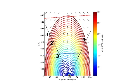
thruster to maintain a given AEP, or to hover further above the AEP for a pure SEP spacecraft. Such a scenario is illustrated in Fig. 8, where the hybrid equithrust contours, with the same parameters as before but with a solar sail of characteristic acceleration of 1 mms-2, five times greater than that suggested as realistic in the near-term, are shown. The equivalent thrust contours of the pure SEP system are overlaid in thin black lines and the field-of-view exclusion of X and Ka-band communications is once again represented. Note that the apparently empty region in Fig. 8 at approximately 0.1 AU out-of-plane represents the region where the required SEP thrust is virtually zero, as the solar sail provides all the required thrust.
It can be seen from Fig. 8 how, with this much greater performance hybrid sail, a relay spacecraft could hover at greater distances above Mars if it was displaced closer to or further from the Sun, with it being possible to station up to 0.226 AU above Mars (although not directly) as opposed to 0.176 AU for the pure-SEP system. Equivalently the relay spacecraft could hover at the same distance of 0.176AU out of the orbital plane, except displaced 0.07AU closer to the Sun - with this performance of sail, the SEP thrust needed is just 184mN, as opposed to a pure-SEP system of 300mN. The minimum amount of thrust required from the SEP component with this solar sail to have a Martian polesitter that would be able to complete the relay in X-band communication would be approximately 180mN – this would require approximately 500mN with SEP alone. In this case perhaps the best trade-off would be to have a hybrid with solar sail of characteristic acceleration of 0.6mms-2 and SEP maximum thrust of 300mN, which would just allow a polesitter in X-band to complete the relay.
It should be remembered here that the analysis only assumes the case of a large SEP system and small solar sail. However, what is evident is that for this particular combination the hybrid sail is most effective in the orbital plane, where, given the direction of the solar radiation pressure, the sail can be oriented to provide exactly the same component of acceleration 𝒂𝑔𝑐 as the equivalent performance SEP thruster. This fact may be of greater use in other potential non-Keplerian orbit missions, especially for those closer to the Sun where the photon pressure is higher. One such mission, that of solar storm warning, will be discussed in Section IV.
Power requirements
Fig. 8 NKO equithrust contours at Mars, projected onto the plane perpendicular to the orbital plane, for the hybrid solar sail with sail characteristic acceleration 1mm s-2. The thin black contours represent the contours
for an equivalent pure-SEP system. The two quasi-horizontal dashed lines represent the field-of-view exclusion angle of X and Ka-band communications respectively.
It is thus required that the thrust level and/or the Isp are substantially lowered, in order to reduce the solar array area
to a more attainable value. If one instead assumes a thruster capable of producing a reduced thrust level of 220mN at a distance of 1AU, namely an Astrium RIT-XT engine operating at 3000s with a 22W/mN of specific power, then the required area of the solar arrays would be just 25.3m2, for the propulsion system only (with no margin, and 25% efficiency of the cells). If a 500W total subsystem power requirement is considered then that area increases to 39.1m2, if a 20% margin is also included. For comparison, consider the Rosetta and SMART-1 missions – the former had a solar array area of 61.5m2 for (approximately) a 3000 kg spacecraft [40], and the latter had a solar array area of about 10m2 for (approximately) a 370 kg spacecraft [41]. Thus the spacecraft for an AEP relay mission at Mars would be somewhere in between Rosetta and SMART-1’s requirements.
of how a spacecraft could be inserted into an orbit to enable such a relay, using the values of thrust and specific impulse of the Astrium engine, see [42].
Contingency Analysis
In order to explore possible recovery options, should the spacecraft suffer thruster failure during the mission to enable continuous communications between Earth and Mars, various contingency scenarios were also analyzed using a direct transcription method based on Finite Elements in Time generated on spectral basis [43, 44], while the equinoctial equations of motion in the Gauss’ form were used to describe the spacecraft motion [45 ,46]. This was combined with a general consideration of how best to utilize the spacecraft between occultations - since the spacecraft are only required to provide a relay service during occultation, maintaining the AEP for a full synodic period is not necessary, and thus one potential strategy is to let the spacecraft drift away from the AEP in between two occultation periods, to conserve fuel. If no contingency occurs, maneuvers can be planned to re-acquire the AEP at minimum propellant cost after one synodic period.
As discussed previously, the blackout period caused by solar conjunction is on the order of one month. However, for the purposes of building significant robustness into the period of communication during conjunction, given the importance of maintaining contact with a human crew as opposed to a robotic one, it was assumed in this study that the blackout period is order of 3 months (90 days). This would therefore allow for optimal communication between Mars and Earth, without having to worry about potentially compromising data rates by “pinching” the Sun-Earth-Mars angle too significantly (e.g., if the conjunction period is scheduled for 40 days, even if direct communication between Earth and Mars is possible before and after this period, it may be significantly less than optimal, and there is no sense in only having the relay spacecraft in position for 40 days). Of course, in a later study this 90 day period could be significantly reduced and fine-tuned as the exact conjunction period was determined, but it provides a reasonable order of magnitude, including sensible margins, for a first-order consideration.
For the analysis, the maximum thrust level of each spacecraft is assumed to be 80mN and the Isp is 3000s. Both relay
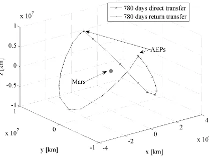
spacecraft are initially in the position as discussed previously for a relay using Ka-band communications – that is, an AEP displaced 45 degrees above the orbital plane, using a thrust of 80mN. This corresponds to a distance of approximately 7 million kilometers above the orbital plane, and the same distance ahead or behind of the planet, as shown in Fig. 9. From these points trajectories are designed to transfer the spacecraft, either from the leading artificial equilibrium point to the trailing AEP (or vice-versa), or from an AEP back to the same AEP - with the goal of having the two spacecraft back in position in displaced orbits in time for the next occultation to begin. The trajectories are optimized to use the least amount of propellant.
Occulted Region
Spacecraft leading Mars Spacecraft
trailing Mars
Plane of Mars orbit
0.
066 au
[image:22.612.206.406.86.229.2]0.047 au
Fig. 9 Initial relative positions of relay spacecraft before transfer for contingency analysis, viewed end-on as from behind Mars.
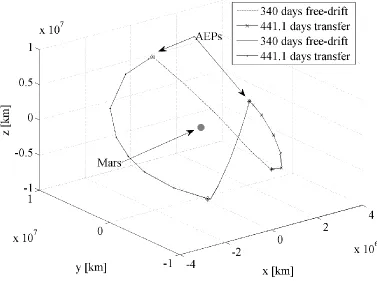
[image:22.612.94.511.317.634.2]The case in which the spacecraft is at an AEP and experiences a failure for 340 days is shown in Fig. 11. From either AEP, the spacecraft drifts downwards until the thruster goes back online and a recovery is performed to reach the opposite AEP. Table 2 provides a summary of these the two cases. In the table the forward transfer refers to the leading-to-trailing transfer and the return transfer refers to the trailing-to-leading transfer.
[image:23.612.113.490.325.610.2]In the case of a failure recovery after 340 days the leading-to-trailing transfer is quite inexpensive. However, the trailing-to-leading transfer has a substantial cost. The total cost for a roundtrip would be about 32.74 kg every 1562.2 days. Note that since, in these calculations, the mass of the spacecraft is assumed to be 1000 kg at the beginning of every transfer, then the total propellant consumption is a slight overestimation of the actual expected cost. Table 2 also shows that, if the maneuvers are planned and no failure occurs (i.e. 0 day drift case), the total cost of a roundtrip reduces to about 14.5 kg every 1562.2 days, or, equivalently, 14.5kg in total across two spacecraft switching position in 781.1 days. Therefore, an exchange of position between trailing and leading points is relatively inexpensive.
Table 2: Summary of leading-to-trailing/trailing-to-leading transfer
Specific impulse Isp (s)
Total propellant consumed
mp (kg)
mp (kg)
forward transfer
mp (kg)
return transfer
Time of Flight (days)
340 day drift 3000 32.7 4.6 28.1 780+780
0 day drift 3000 14.5 4.6 9.9 780+780
An alternative scenario is that the spacecraft is maneuvered to return to the original AEP. Thus, if no contingency occurs, leading-to-leading transfers and trailing-to-trailing transfers are planned to re-acquire respectively the leading and the trailing AEP. If a failure occurs, the spacecraft drifts away and after a number of days the recovery maneuver starts. The cost of a recovery maneuver is evaluated for a drift time of 0, 100, 200, 300 and 390 days. The propellant cost is represented in Fig. 12, where the drift time is called time-to-intervention, and the resultant analysis shows that if no failure occurs, an AEP-to-AEP transfer has a minimal cost of less than 8 kg, for the roundtrip, for the leading point and less than 5 kg roundtrip for the trailing point.
[image:24.612.102.503.350.671.2]In the case of a failure at the leading point, the cost can grow up to 50 kg roundtrip while it remains contained for a failure at the trailing point. In the former case the spacecraft flies around Mars before re-acquiring the AEP, in the case of a drift time of 390 days. Therefore, if a single spacecraft is used and a failure occurs at the leading point a leading-to-trailing transfer is recommended. Vice versa, if a contingency occurs at the trailing point a trailing-to-trailing transfer is recommended.
This analysis optimizes the return to the AEP to minimize the propellant consumption. However, the return time (time to go from one AEP back to the same AEP), in some cases, could be 681 days, i.e. 100 days before the next occultation. This situation is unfavorable because the spacecraft would need to maintain the AEP with constant thrust for an extra 100 days every synodic period, in addition to the 90 day-burn already planned for during the occultation. An approximate estimate suggests thrusting at the AEP for the extra 100 days would require around 23kg of propellant, in addition to the less than 8 or 5 kg required to do this fuel-efficient transfer, resulting in total propellant consumptions of 31kg and 28kg (approximately).
[image:25.612.88.537.423.585.2]Instead, the spacecraft can be forced to return to the AEP after 1 synodic period exactly, as shown in Fig. 13, which shows the transfer trajectories for different drift times, while Fig. 14 shows the propellant consumption for different drift times. From Fig. 14, it can be seen that for the trailing AEP the cost remains almost constant (the variation is between 24 and 25 kg) for different drift times.
Fig. 14 Propellant cost against time-to-intervention for AEP-AEP contingency transfer. Fixed return period.
Fixing the leading-to-leading or trailing-to-trailing re-acquire time to 1 synodic period results in propellant consumptions of 25 and 24 kg, approximately, which is clearly more efficient overall than the previous situation where the transfer trajectory itself is optimized for fuel efficiency but the spacecraft comes back to the AEP too early and has to expend a lot of energy to stay there. However it must be noted that this is still less efficient than the AEP-swapping system, which requires a total of around 14.5kg for two spacecraft to switch position from leading-to-trailing and vice-versa in one synodic period. Again, if the engine fails to thrust, the situation can be recovered with increasing amounts of propellant for ever-increasing failure times, although interestingly only for the leading-to-leading case (where the increase is dramatic, as per before), with it being approximately constant for the trailing-to-trailing case.
Finally, it is worth remembering that, in-between periods of occultation when the AEP is no longer need to be maintained by the relay spacecraft, there are already existing communications relays which provide virtually continuous coverage of the entire Martian surface - as outlined by e.g. Strizzi et al. [32] and Pernicka, Henry & Chan [47]. Thus, it is envisaged that continuous communications for the entire synodic period of a Martian orbit would be achieved by both the mechanism outlined in these aforementioned references and the one discussed at length in this paper. This could be done either by having four spacecraft, two at the Lagrange points in halo orbits and two to occupy the artificial equilibrium points when required, or by investigating the possibility of only having two relay spacecraft and transferring them into the alternating halo/non-Keplerian orbits as required.
Extension to elliptic restricted three-body problem
In detailing such a communications relay, non-Keplerian orbits formulated in the circular restricted three-body problem (CRTBP) were considered for simplicity. However, the implications of eccentricity (of the primaries) on the required instantaneous thrust and ∆𝑣 are considered here by recasting the problem into rotating-pulsating coordinates associated with the elliptic restricted three-body problem (ERTBP).
When the effect of eccentricity is included, the continuous low-thrust required to induce a displaced periodic orbit in the inertial frame that corresponds to an artificial equilibrium point in the rotating-pulsating frame is no longer constant, but varies with true anomaly over an orbit – with the acceleration in the ERTBP required to occupy an equilibrium point in the rotating-pulsating frame being given by a low-thrust feed-forward control of the form,
𝑢
𝑥= 𝑎
𝑥1 + 𝑒 cos 𝑓
2𝑢
𝑦= 𝑎
𝑦1 + 𝑒 cos 𝑓
2(11)
𝑢
𝑧= 𝑎
𝑧+ 𝑧𝑒 cos 𝑓 1 + 𝑒 cos 𝑓
2where 𝑎𝑥, 𝑎𝑦, and 𝑎𝑧 are constant, 𝑒 is the eccentricity of the orbit, and 𝑓 is the true anomaly. Note that the accelerations are given in non-dimensional units– for the full details of this derivation, see Appendix A. Note also that when e=0 the controls degenerate to the constant thrust required to induce non-Keplerian orbits in the CRTBP.
For example, consider the case of the relay with a single pure-SEP spacecraft, which requires 300mN of thrust to displace high enough above Mars to enable a relay in X-band communications in the CRTBP. In this case the thrust would be constant but in the ERTBP it would need to smoothly vary according to Eqs. (11), as shown in Fig. 15.
In this example the minimum instantaneous value of thrust required to occupy this point would be 225mN, and the maximum value would be 392mN. Over the course of an orbit the average value of the thrust is approximately 302mN, which is only 0.7% greater than the constant thrust requirement in the CRTBP. However, when considering the feasibility of a mission involving non-Keplerian orbits, the eccentricity of the primary bodies will have a significant impact on the catalogue of orbits obtainable given a maximum instantaneous thrust capability.
This slight increase in the average thrust per orbit required in the ERTBP to occupy approximately the same point of that of the CRTBP leads to an increase in the required ∆𝑣 per orbit. An indefinite integral for the ∆𝑣, given the feed-forward control acceleration in Eqs. (11) is given by,
∆𝑣 = 𝑎
𝑥2+ 𝑎
𝑦 2+ 𝑎
[image:28.612.152.458.358.662.2]𝑧
+ 𝑧𝑒 cos 𝑓
21 + 𝑒 cos 𝑓
4𝑑𝑓 12
A useful analytic approximation of this can be derived by expanding the integrand to 3rd order in e about e0and integrating with respect to the true anomaly over one orbit period 0 ≤ f ≤ 2π. Defining the constant 𝐾 = 𝑎𝑥2+ 𝑎𝑦2+ 𝑎𝑧2 for simplicity the approximate Δv
per elliptic non-Keplerian orbit, call Δve
,
is,∆𝑣
𝑒=
𝜋(2𝐾
2
2 + 𝑒
2+ 4𝑎
𝑧
𝐾𝑒
2𝑧 + 𝑎
𝑥2+ 𝑎
𝑦2𝑒
2𝑧
2)
2𝐾
3/213
Note that when e = 0 the Δv per orbit reduces to ∆𝑣0= 2𝜋
𝑎
𝑥2+ 𝑎
𝑦2+ 𝑎
𝑧2, corresponding to the non-dimensional constant thrust magnitude in the circular case. The percentage increase in Δv per orbit due to eccentricity is then given by 100 × (∆𝑣𝑒− ∆𝑣0)/∆𝑣0, which is explicitly,% 𝑐𝑎𝑛𝑔𝑒 𝑖𝑛 ∆𝑣 = 25𝑒
2(2 +
𝑧 4𝑎𝑧𝐾+𝑧 𝑎𝑥 2+𝑎𝑦2
𝐾2
) (14)
This calculation gives an indication of how the eccentricity will affect the ∆𝑣 requirement for non-Keplerian orbits. For example a 1000 kg spacecraft in a displaced non-Keplerian orbit at x = 1.5451 AU from the Sun, y = 0.0838 AU and z = 0.0419 AU from Mars, where x, y, z are rotating-pulsating co-ordinates requiring continuous constant acceleration in the circular case of 𝑎𝑥= 1.3881 × 10⁻⁴𝑚𝑠−2, 𝑎
𝑦 = 7.3153 × 10⁻⁶𝑚𝑠−2, 𝑎𝑧 = 6.7045 ×
10−5𝑚𝑠−2 (converting into non-dimensional units and substituting into (14)) gives a percentage change in Δv per orbit due to eccentricity (𝑒 = 0.09) of 0.6%. As such, while the effect of eccentricity cannot be neglected when considering the instantaneous thrust requirements, the time averaged effect of eccentricity on Δv can be neglected in this first-order analysis.
IV. A Hybrid Propulsion Solar Storm Warning Mission – AreoStorm
Currently, probes at the Earth-Sun L1 point can provide approximately 30 minutes advance warning of an
approaching Coronal Mass Ejections (CME). In 1999, the ST-5 GeoStorm mission proposal suggested the use a solar sail of characteristic acceleration 0.169mm s-2 to access an artificial displaced orbit at a point sunward of Earth-Sun L1 point (0.993AU from the Sun), maintaining station at 0.985 AU [10]. Such a spacecraft would increase
the warning time of an approaching magnetic storm by a factor of approximately 3. For future human or enhanced robotic exploration of Mars knowledge of approaching solar storm will be even more critical than at Earth, as the thinner Martian atmosphere and weaker magnetic field will provide significantly less natural protection, and a human crew may be some distance from suitable shelter. However, due to the inverse square reduction in solar sail acceleration with distance from the Sun, the ST-5 sail would provide an acceleration of only 0.07 mm s-2 at Mars. Such a sail would in-turn enable a 100 kg spacecraft in an artificial displaced orbit at a point sunward of Mars-Sun L1 point (1.513AU from the Sun), maintaining station at 1.506 AU from the Sun, in-effect doubling the warning
A similar mission concept can be considered with a continuous low-thrust SEP spacecraft. Assuming once again, a spacecraft mass of 𝑚 = 1000kg, with a thrust magnitude of 80 mN, as discussed previously, an AEP can be enabled at a distance of approximately 1.503 AU from the Sun, increasing the storm warning time over a spacecraft in a Mars L1 halo orbit by a factor of 2.5. Consider now the addition of a solar sail to such an SEP mission concept.
Using the same parameters as those in Fig. 7, that is, a solar sail of characteristic acceleration 0.2 mm s-2, it can be seen that this warning time can be further improved, as illustrated by Fig. 16, due to the additional acceleration contribution made by the solar sail. Note that this slightly higher characteristic acceleration, than the ST-5 sail, would in-effect provide a matching pure solar sail performance, with a total mass again of 100 kg, to the previously discussed pure SEP mission.
Once again limiting the SEP thrust magnitude to 80 mN, it is seen from Fig. 16 that an AEP can be enabled at a distance of approximately 1.485 AU from the Sun, increasing the storm warning time over a spacecraft in a Mars L1
halo orbit by a factor of five, assuming a CME has a constant propagation speed, which is not strictly true, but is a reasonable assumption for this analysis. Equivalently, the solar sail can be used to reduce the required thrust magnitude from the SEP system, at the expense of storm warning time, and hence extend the spacecraft operational lifetime.
Fig. 16 NKO equithrust contours, with thrust direction arrows, at Mars, projected onto the plane perpendicular to the orbital plane, for a hybrid sail with characteristic acceleration 0.2 mm s-2 and other
It is also of interest to push the design parameters of such a hybrid spacecraft and determine what thrust and/or solar sail would be needed to achieve a warning time increase of a factor of about 10 over that given by stationing at L1.
Such a warning spacecraft must be stationed at approximately 0.07 AU from Mars and would require a total thrust magnitude of order 290 mN. Table 3 summarizes how a hybrid spacecraft can trade-off the available SEP thrust magnitude, ranging from 80 – 145 mN, with the sail characteristic acceleration, ranging from 0.3 – 0.5 mm s-2, to achieve a factor of 10 increase in storm warning time. Table 3 also summarizes the previous results of this section, which are then also detailed in Fig. 17 which shows the corresponding the sail design space for each mission detailed in Table 3. In Fig. 17 the sail area is determined from the payload fraction the sail is able to carry given a non-sail mass of 1000kg for a given characteristic acceleration, assuming a range of sail assembly loading values.
[image:31.612.77.542.445.658.2]It can be seen from Fig. 17 that the available design space decreases as the sail performance increases. But from Table 3 and Fig. 17 together it can be seen that in future it may be possible to trade-off development of one aspect of the hybrid against the other, depending on mission requirements. Solar Electric Propulsion is the more mature technology, in relative terms at least, and so improvements in that technology may be more incremental and reliable in the short term, but the potential of solar sailing is almost completely untapped, being as it is considerably less well-developed. Additionally, one of the major benefits of increasing sail performance is to help to reduce the propellant consumption from the SEP part, and thus extend mission durations significantly.
Table 3: Summary of potential AreoStrorm missions
Opportunity Name
Approximate station distance from Mars (AU)
SEP Thrust
(mN)
Sail acceleration Magnitude of storm warning time factor Characteristic
(mm s-2)
Actual (mm s-2)
L1 station 0.007 0 0 0 1
Pure Sail (ST-5) 0.014 0 0.17 0.074 2
Enhanced Pure Sail 0.018 0 0.20 0.087 2.57
Pure SEP 0.017 80 0 0 2.43
Hybrid, as per Fig. 16 0.035 80 0.20 0.087 5
x10 Warning, a 0.070 80 0.49 0.210 10
x10 Warning, b 0.070 100 0.44 0.190 10
x10 Warning, c 0.070 120 0.393 0.170 10
Fig. 17 Solar sail design space for the hybrid AreoStorm mission with varying warning storm.
Of course, it is important to remember here that although equithrust surfaces are considered, no propulsion system actually delivers an equal thrust throughout the lifetime of the spacecraft, due to either depletion of reaction-mass or, in the case of solar sailing, the degradation of the optical surface [33]. As such, the propulsion system would have to be throttled to adjust for either the increasing (for depletion of reaction-mass) or decreasing (for degradation of the optical surface) acceleration vector magnitude. It is also worth commenting that this is not a true like-for-like comparison, in terms of the mass of the pure-SEP and hybrid spacecraft. The above discussion simply compares the acceleration available to two different spacecraft, and thus, in that respect, it is reasonably obvious to say that adding a sail to an SEP system will produce better performance than a pure-SEP system alone - but it is still useful to quantify exactly how much better, given achievable solar sail performances. A more in-depth analysis (beyond the scope of this paper) would require a detailed mass budget for both spacecraft to be determined and from that the relative acceleration of a pure-SEP spacecraft and a hybrid spacecraft of equal masses could then be compared.
0 5 10 15 20 25 30 35 40
0 10000 20000 30000 40000 50000 60000 70000 80000 90000 100000
Sa
il
A
ss
e
mb
ly
L
o
ad
in
g
(g
m
-2)
Sail Area (m2) ST-5 Sail
V. Conclusion
Two novel mission concepts have been presented which use continuous and constant low-thrust propulsion to enable highly non-Keplerian orbits in support of future high-value asset exploration of Mars. Detailed analysis of a Mars communications relay showed that current, or near-term, technology, such as the QinetiQ T6 thruster can be used to enable continuous communications between Earth and Mars during solar conjunctions, it was also found that a Ka-band communication system, rather than an X-Ka-band system, significantly relaxed the propulsion system requirements. The use of solar electric propulsion and a hybrid solar sail/solar electric propulsion spacecraft were considered for the communication relay, the addition of a modest solar sail proves some advantages for the case of a communications relay using Ka-band and particularly for communication with assets stationed near the poles during summertime. Several propulsion system failure and contingency schemes were considered, with it being shown that transferring a spacecraft between potential relay locations is relatively inexpensive. Analysis of a solar storm warning mission was presented for the first time. It was found that for this mission to provide a meaningful advantage over a conventional Sun-Mars L1 halo orbit a hybrid solar sail/solar electric propulsion spacecraft was
required. Such hybrid propulsion was found to reasonably offer a factor of five increase in warning time. Finally, the effect of Mars orbit eccentricity was briefly considered and found to impact the time averaged analysis, however the effect of Mars orbit eccentricity was found to be significant when considering maximum and minimum instantaneous force requirements.
Appendix A: Derivation of the feed-forward control accelerations in the ERTBP
The elliptical restricted three-body problem (ERTBP) including continuous low-thrust propulsion in the rotating-pulsating frame can be used as the dynamical model to describe a low-thrust spacecraft under the gravitational influence of two massive bodies. This model is derived by performing a simple coordinate change from the rotating-barycentric frame to the rotating-pulsating frame. In order to obtain the equations of motion in the most convenient form the equations are derived using the procedure of Gurfil and Meltzer [48].
The small primary orbits the large primary on an elliptic orbit with eccentricity 𝑒, which complies with the two-body Keplerian motion. The distance between the two primaries, 𝜌, depends upon the true anomaly, 𝑓, through the conic equation,
𝜌 = 𝑝/ 1 + 𝑒 cos 𝑓 (𝐴1)
where 𝑝 is the semi-latus rectum 𝑝 = 𝑎(1 − 𝑒2) and 𝑎 is the semi-major axis. The rate of change of the true anomaly satisfies 𝑓 = /𝜌2 where is the magnitude of the angular momentum, given by 2= 𝐺(𝑚
1+ 𝑚2)𝑝.
Here 𝐺 is the universal gravitational constant and 𝑚1, 𝑚2 denote the mass of the first and second primary respectively. An appropriate set of units is introduced so that the gravitational constant 𝐺 = 1, the semi-major axis 𝑎 = 1 and we define the constant 𝜇 = 𝑚2/(𝑚1+ 𝑚2) where 𝑚1 is located at −𝜌𝜇, 0,0 𝑇 and 𝑚