1
Continued Operation of Multi-Terminal HVDC Networks Based on Modular Multilevel Converters
G.P. Adam1, R. Li1, D. Holliday1, S. Finney1, L. Xu1, B.W. Williams1, R. Uda2, K. Kuroda2, R. Yamamoto2 and H. Ito2
1
University of Strathclyde Royal College Building
204 George Street Glasgow G1 1XW
UK
2
Mitsubishi Electric Corporation Energy and Industrial Systems Group
2-7-3 Marunouchi Chiyoda-Ku Tokyo 100-8310
Japan
Summary
A comprehensive study that explores the possibility of using passive networks and active converter control to facilitate continued operation of multi-terminal HVDC networks with minimum interruption during pole-to-pole dc short-circuit faults is presented. The primary objective of this study is to achieve continued operation of any multi-terminal HVDC network using relatively slow dc circuit breakers (with minimum operation time of 10ms), without over-stressing converter switches and without converter dc link voltages falling below the peak ac line voltage. The validity of the proposed method is confirmed using time-domain simulations. Results obtained from iterative simulations confirm the possibility of further extension of fault clearance time to more than 10ms, but at the expense of increased passive component size.
Keywords
Fault clearance time; modular multilevel converter; multi-terminal high-voltage dc network; pole-to-pole dc fault.
I.
I
NTRODUCTIONIn recent years, voltage source converter (VSC) based multi-terminal high-voltage dc (MT-HVDC) networks have received considerable attention from academia and industry, as they provide a platform that can be exploited to facilitate large power transfer over long distances, with increased power flow control flexibility and improved security of supply when compared to point-to-point HVDC links. Also, they provide a cost-effective solution for connection of large-scale onshore/offshore wind farms dispersed over wide areas of land/sea, with the minimum number of converters and cables. However, the low impedance of VSC based HVDC networks makes them vulnerable to dc faults which are characterised by rapid, network-wide, voltage collapse and high fault current at the converter terminals. To date, the absence of reliable and cost-effective dc circuit breakers, and the lack of proven
21, rue d’Artois, F-75008 PARIS
LUND 2015
2 protection philosophies have deterred utilities and transmission system operators (TSO) from adopting MT-HVDC.
Two approaches being widely investigated to overcome the challenges of MT-HVDC are:
Reverse blocking converters which can protect converter devices and eliminate the component of dc fault current contributed by the ac network. This approach can drastically reduce the design requirements for dc circuit breakers (DCCB), or even allow ac circuit breakers (ACCB) to be used for dc fault clearance. The main disadvantage of this approach is that all converter stations must block until the fault is cleared with a resulting loss of power exchange between all terminals. Also, the entire network voltage drops to zero when converter terminals are blocked and the network must be re-energised via the converter stations [1]. A dedicated control strategy is therefore required to perform controlled recharge of the dc cables for the entire network.
Fast-acting dc circuit breakers (DCCB) may be used to isolate the faulty part of the MT-HVDC network, while allowing continued operation of the healthy part of the network[1]-[3]. This approach is likely to be accepted by TSOs as it brings the protection of MT-HVDC networks into line with techniques used in conventional ac networks. Both hybrid [4] and mechanical [5] DCCB have been proposed for dc fault isolation in HVDC grids.
The results of a comprehensive study investigating modifications to the configuration and operation of MT-HVDC networks, that may allow the constraints on DCCB performance to be relaxed, are presented. It is shown that with appropriate converter control and placement of additional passive elements on the dc side, the fault clearance time in an MT-HVDC network can be extended to 10ms and beyond, without overcurrent of converter components or significant compromise to its continued operation.
II.
B
RIEFR
EVIEW OFM
ODULARM
ULTILEVELC
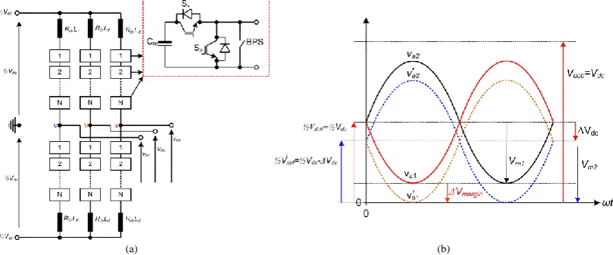
ONVERTERSFigure 1(a) shows a generic three-phase half-bridge modular multilevel converter (HB-MMC) with N
cells per arm. Each arm of the HB-MMC consists of a series of cells, each of which is rated at a fraction of the full dc voltage such that Vcell = Vdc/N. According to its switching state, each cell can contribute a voltage of 0 or Vcellwhich can be summed to produce a controlled voltage in the upper and lower arms. This structure removes the requirement for series switching of the IGBTs and facilitates the use of high-efficiency, low-distortion, multi-level modulation strategies. Arm inductance Ld acts to attenuate switching frequency harmonics in the ac output current and also limits the common-mode current due to unbalance between the combined upper and lower arm voltages and the dc supply. The dc fault response of the HB-VSC is similar to that of a two-level dc converter, in so far as control of the ac current is not possible once ∆Vmargin approaches zero, as illustrated in Figure 1(b). Beyond this point, the cell capacitors provide an uncontrolled path for ac fault current into the dc short circuit. However, unlike a two-level VSC, discharge of the converter capacitance can be prevented by blocking the cell IGBTs in the event of a dc path overcurrent. Bypass devices (BPS) shown in Figure 1(a) may be inserted to relieve the anti-parallel diodes from overcurrent during a dc short-circuit fault. These may take the form of mechanical contactors or high-capacity semiconductor switches such as thyristors.
Once the cell IGBTs are blocked the dc fault behaviour resembles that of an uncontrolled diode rectifier. The fault profile is dominated by the system inductance. The ac side inductance, comprising
3 PQ transfer between the converter and the ac system. Additional dc link inductance may be added to slow the rise of fault current, but has no impact on the steady-state value.
(a) (b)
Figure 1: (a) Half-bridge modular multilevel converter (MMC), and (b) illustration of voltage developed across its upper and lower arms
In order for the converter to maintain control of ac current during dc voltage drop, the converter must be able to generate an ac voltage whose amplitude is similar to the amplitude of the ac supply voltage. The ac voltage produced by the converter is controlled by the modulation index M, and is given as
) ( 2V sin ωt
M
Vc dc (1)
The lowest value to which the dc voltage can be allowed to drop before the converter starts to lose ac current control is therefore given by
) ( max (min) 3 2 2 L L s dc V M V (2)
where Vs(L-L) is the phase-to-phase rms ac supply voltage.
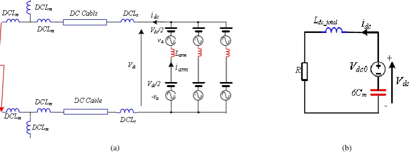
If space vector modulation (SVM) is used, Mmax = 2/√3 whereas for sinusoidal pulse width modulation (SPWM), Mmax= 1. Thus for a system with a converter voltage of 392kV, the lowest values to which the dc voltage can drop without losing converter control are 554kV for SVM and 640kV for SPWM. During normal operation, the voltages developed across the upper and lower arms of each MMC phase contain a dc component of ½Vdc and an ac component, as illustrated in Figure 2(a). Providing the dc voltage remains sufficiently high during a remote dc fault, the ac current can be controlled. Analysis of additional arm and dc currents need only consider, therefore, the behaviour of the dc circuit. From Figure 2(a), it can be seen that additional current in the arm and dc link is produced by cell capacitor discharge during a dc fault. Further circuit analysis for the configuration shown in Figure 2(a) (which, for simplicity, does not consider the dc cables) results in a circuit resembling the simple 2nd order system shown in Figure 2(b) and described by (3), where Cm is the equivalent total capacitance in each arm and Vdc0 is the initial dc link voltage.
) (
0
0 e sin ωt β
ω ω V
Vdc dc δt
) ( 0 ωt sin e ωL V I δt dc_total dc dc (3) where total dc L R _ 2 , m total dc C L 6 1 _ 2 0 , 2 2 0
2 , and
[image:3.595.77.524.108.294.2]4
(a) (b)
Figure 2: (a) Section of illustrative HVDC link, and (b) Equivalent dc circuit during a dc fault
III.
P
ROPOSEDC
ONTINUEDO
PERATION ANDI
LLUSTRATIVET
ESTS
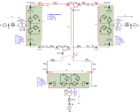
YSTEMThe use of passive networks in combination with converter control is proposed to enable continued operation of MT-HVDC networks using DCCBs with increasingly relaxed design constraints (i.e. minimum operation time of 10ms). These passive networks aim to decouple the remote converters connected to the healthy part of a given MT-HVDC network from the impact of the dc fault by increasing the electrical distance between these converters and the fault location. Should large dc inductances be employed in these passive networks, therefore, the speed of dc fault propagation within the dc network is greatly reduced. In addition, the dc inductances can limit the rise of dc fault current. Moreover, it is proposed that all remote converters connected to the healthy part of a given MT-HVDC network are switched to dc voltage control mode in an attempt to maintain higher minimum dc voltage across the healthy part of the MT-HVDC network for an extended period of time. The technical viability of the proposed continued-operation strategy is assessed using the illustrative three-terminal HVDC network shown in Figure 3. It is assumed that the pole-to-pole dc fault applied at point ‘F’ is permanent and cleared using DCCBs 10ms after fault initiation. Converter terminals VSC1, VSC2 and VSC3 are configured as follows:
VSC1 acts as an active dc voltage regulator (ADCVR), setting the dc voltage level for the entire dc
network at ±400kV (800kV pole-to-pole), with unity power factor at B1.
VSC2 and VSC3 are active power regulators (APR), and inject 700MW and 500MW into B2 and
B3 respectively, at unity power factor.
The pre-fault power flow directions in Figure 3 are assumed to be positive. A dc short-circuit fault applied at point ‘F’ is cleared by opening DCCB3 and DCCB43 at time tocb = 10ms. For simplicity, this study assumes VSC3 is blocked 20µs following fault initiation. This timescale is consistent with
[image:4.595.96.498.77.229.2]5
Figure 3: Illustrative three-terminal test system showing locations of additional passive components
IV.
S
IMULATIONS
TUDYTo validate the analysis described in Section II, simulation results produced using the three-terminal HVDC system are compared with analytical solutions obtained using (3). In the simulation study, the initial power flows are set to zero (for ease of visualisation), DCLx = 100mH, DCLy = 600mH and
DCLm= 600mH. Each arm of the MMC considered has 380 cells, each with cell capacitance of 5.5mF. Table 1 compares the dc voltage and current 5ms and 10ms following fault initiation.
Table 1: Comparison of simulated and calculated results
Parameter t = 5ms t = 10ms
Simulated Calculated Simulated Calculated
Vdc (kV) 755 768 665 676
Idc (kA) 1.0 1.03 2.0 1.98
The simulation and analytical results are in good agreement. The small differences in the dc voltages are mainly due to the fact that in the simulation, the dc voltage components produced by each arm are slightly less than half of the internal cell capacitor voltage, thereby resulting in slightly reduced dc voltage output.
To substantiate the discussions presented in Section III, the illustrative three-terminal HVDC network of Figure 3 is simulated. A dc short-circuit fault is applied at t = 0.7s and cleared t = 0.71s (i.e. after 10ms) using DCCB43 and DCCB3. When the dc fault is detected, VSC1 and VSC2 remain unblocked,
[image:5.595.146.450.561.625.2]6
t = 0.75s, and resumes power transfer at t = 0.76s by linearly increasing its output power from 0 to 700MW.
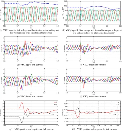
To demonstrate that correctly sized additional inductance can constrain dc current injection into the MMC upper and lower arms, the case with DCLx = 100mH, DCLy = 400mH and DCLm = 450mH is presented. The results in Figure 4 show that, although the dc link voltages of VSC1 and VSC2 remain
above the peak values of their corresponding ac line voltages, increased current stresses are observed in the upper and lower arms of VSC1 and VSC2. These overcurrents are mainly the result of the dc
fault current and, to a lesser extent, a controlled ac component drawn from grids G1 and G2 in an
attempt to support the dc link voltages of VSC1 and VSC2. However, the peak arm currents shown in
Figure 4(c) to (f) remain below the safe threshold. Figure 4(g) and (h) show VSC1 and VSC2 positive
and negative pole dc currents during the fault. This example shows that with properly sized DCLm and
DCLy, the dc fault clearance time in an MT-HVDC network can be extended without exposing converter switches and DCCBs (if they are included) to excessive current stresses.
(a)VSC1 input dc link voltage and line-to-line output voltages at
low-voltage side of its interfacing transformer
(b)VSC2 input dc link voltage and line-to-line output voltages at
low-voltage side of its interfacing transformer
(c)VSC1 upper arm currents (d)VSC2 upper arm currents
(e)VSC1 lower arm currents (f) VSC2 lower arm currents
[image:6.595.82.510.276.735.2](g) VSC1 positive and negative dc link currents (h) VSC2 positive and negative dc link currents
Figure 4: Waveforms for VSC1 and VSC2 obtained when a pole-to-pole fault is applied at point ‘F’
with DCLx = 100mH, DCLy = 400mH and DCLm = 450mH
Vdc
, V
L
-L
a
b
c
(
kV
)
Vdc
, V
L
-L
a
b
c
(
kV
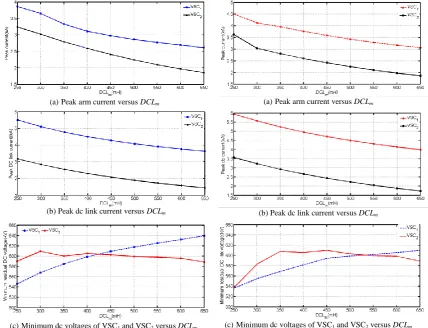
7 Figure 5 and Figure 6 summarise the peak arm and dc link currents in VSC1, VSC2 and VSC3, and the
minimum dc voltages for VSC1 and VSC2, versus DCLm for tocb = 10ms and tocb = 12.5ms when
DCLx = 100mH and DCLy = 400mH. These results show that the proposed method can facilitate continued operation of the MT-HVDC network using DCCB, with relaxed design constraints for dc fault isolation. The figures also show that operating all of the converters connected to the healthy part of the grid in active dc voltage regulation (ADCVR) mode during the fault period can improve the minimum dc link voltage of these converters. Thus, the uncontrolled ac current in-feed from the ac grids to the converters connected to the healthy part of the network is avoided, and transient currents and power flows in the dc side are minimised. These improvements are achieved without violating the maximum current threshold for an un-blocked converter.
(a)Peak arm current versus DCLm (a)Peak arm current versus DCLm
(b)Peak dc link current versus DCLm (b)Peak dc link current versus DCLm
(c)Minimum dc voltages of VSC1 and VSC2 versus DCLm (c)Minimum dc voltages of VSC1 and VSC2 versus DCLm
Figure 5: Summary of the maximum arm and dc link currents, and minimum dc link voltages versus DCLm when tocb = 10ms
Figure 6: Summary of the maximum arm and dc link currents, and minimum dc link voltages versus DCLm when tocb = 12.5ms
V.
C
ONCLUSIONS8 network has confirmed the effectiveness of the proposed technique and has validated the time-domain simulation method used in the study.
VI.
R
EFERENCES[1] T. Jonsson, P. Lundberg, S. Maiti and Y.J. Hafner, ‘Converter Technologies and Functional Requirements for Reliable and Economical HVDC Grid Design’, CIGRE, Canada Conference, No.226, Alberta, Canada, 2013.
[2] D. Schmitt, Y. Wang, T. Weyh and R. Marquardt, ‘DC-side fault current management in extended multiterminal-HVDC-grids’, 9th International Multi-Conference on Systems, Signals and Devices (SSD), pp.1-5, 2012.
[3] C.M. Franck, ‘HVDC Circuit Breakers: A Review Identifying Future Research Needs’, IEEE Transactions on Power Delivery, Vol.26, No.2. pp.998-1007, 2011.
[4] F. Dijkhuizen and B. Berggren, ‘Zoning in High Voltage DC (HVDC) Grids using Hybrid DC breaker’, EPRI HVDC and FACTS Conference, Palo Alto, USA, 2013.