Design of compliant parallel grippers using the
position space concept for manipulating
submillimiter objects
Guangbo Hao*
School of Engineering University College CorkCork, Ireland
*Corresponding author: G.Hao@ucc.ie
Xianwen Kong
School of Engineering andPhysical Sciences Heriot-Watt University Edinburgh EH14 4AS, UK
Wenlong Chang
†, Xichun Luo
Department of Design, Manufacture and Engineering Management
University of Strathclyde Glasgow G1 1XJ, UK
†Presenter
Abstract—The structure or configuration of compliant mechanisms can be reconfigured through changing the positions of each compliant module thereof within their position spaces. A number of 1-DOF 2-PRRP compliant parallel grippers (CPGs) can be obtained using the structure reconfigurability for manipulating micro-structures. Even with the geometrical parameters for the system’s pseudo-rigid-body model (PRBM) and each compliant module kept at the same values, the position of each compliant joint can be anywhere within its position space. The performance of the resulting CPG varies with the position of the compliant joint. In this paper two typical CPG designs are presented and analyzed. Comparisons of FEA simulaiton results shows that the input-output kinematic relationship of the non-compact design agrees better with that of the PRBM due to its better load transmissibility. One can design different structures based on specific design requirements.
Keywords—gripper; compliant mechanisms; micro-structures; position space; conceptual design
I. INTRODUCTION
Manufacturing is an essential part of the EU economy which contributes major portions of Gross Domestic Products (GDP), exports and economic resilience. Increasing competitiveness of high value manufacturing sector through high-level process control or monitoring [1] has been set up as an important agenda in the EU Horizon 2020 programme. Using robotic gripper to automatically handle structures (such as 1mm dimension of micro-lens) for high-precision manufacturing has become an important research topic for competitive manufacturing [2].
Traditional rigid-body robotic grippers often suffer from poor resolution and repeatability due to the joint’s backlash and friction and are therefore not suitable for manipulating micro-structures. However, compliant mechanism based designs, transferring force or displacement through the elastic deformation of one or more flexible members within the structure (i.e., jointless), can overcome the above problems. Due to their advantages of reducing the number of parts (thereby raising the system
reliability), reducing the assembly and fabrication cost, and increasing the system performance, such grippers have been successfully used in the applications of precision engineering, biomedical devices and MEMS [3-11].
This paper focuses on the design of compliant parallel grippers (CPGs) for manipulating micro-structures. A CPG is generally a 1-DOF compliant parallel mechanism composed of a base, compliant members, and two or more jaws. The jaws of a CPG are often indirectly driven by a linear actuator to grasp an object within the jaws. CPGs, by fine control, can achieve micro/nano-manipulation precision specified in terms of motion repeatability, accuracy (lack of error) and actual resolution (actual minimum incremental motion). There are generally two manners of gripping for the jaws: angular and parallel [5]. Angular one may lead to a sliding motion between the gripped object and the jaw, while this is maximally avoided with the parallel gripping arrangement. The parallel gripping can also provide an even distribution of the gripping force over the manipulated sample and minimize the stress distribution on the grasped object [6].
Most of emerging CPGs are based on the well-known kinematics based substitution methods using traditional slider-crank mechanisms, parallelogram mechanisms, and/or straight-line four-bar linkages [6, 8-10]. Topology optimization based methods have also been employed to design CPGs [11]. Displacement amplification mechanisms are usually involved in these designs. However, how to improve CPGs with regard to compactness, simplicity, and/or motion range is still an open issue.
This paper aims to design new CPGs with distributed compliance using the structure reconfigurability through the concept of position space for compliant joints. This paper is organized as followed. Detailed design is described in Section II. Section III conducts the analytical kinetostatic modeling for the CPG based on the pseudo-rigid-body model (PRBM) followed by case studies for two typical designs in Section IV. Further considerations are discussed in Section V and conclusions are drawn in Section VI. Proceedings of the 21st International Conference on
II. DESIGN DESCRIPTION
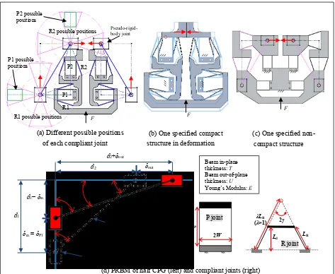
As show in Fig. 1, a CPG is proposed based on a 1-DOF 2-PRRP mechanism [12]. Here and throughout this paper, P and R stand for a prismatic joint and a revolute joint respectively. The CPG is obtained by replacing each joint in the 2-PRRP mechanism with the compliant counterpart. Here, the compliant P joint is a basic parallelogram mechanism and the compliant R joint is an isosceles trapezoidal flexure mechanism with its remote rotation center coinciding with the center of the corresponding R joint (Fig. 1(d)). This 2-PRRP mechanism itself is a displacement amplification mechanism for amplifying the input displacement. Therefore a separate displacement amplification mechanism is not needed.
The structure of compliant mechanisms is reconfigurable through changing the positions of each compositional compliant module thereof within the
position space [13]. The position space of a compliant module is the combination of all permitted positions in a system where the constraint of this compliant module in the system remains unchanged when the position of the compliant module changes relative to its adjacent compliant module rather than being considered in isolation. The position space can be identified using the screw theory based method as reported in [13].
[image:2.595.61.534.302.690.2]The CPG can therefore have a variety of structures/configurations through changing the positions of each compliant P/R joint (Fig. 1(a)). Even through the geometrical parameters (Fig. 1(d)) of the system’s PRBM and each compliant joint/module are kept at the same values, the position of each compliant joint can be anywhere within its position space (Fig. 1(a)). Two typical designs, compact one and non-compact one, are shown in Figs. (b) and (c).
Figure 1. Conceptual design of planar 2-PRRP CPGs
L d1− δin
δin = δP1
d1
α0 α β
β0
δout d2
d2+δout
Initial position
(d) PRBM of half CPG (left) and compliant joints (right)
Beam in-plane thickness: T
Beam out-of-plane thickness: U
Young’s Modulus: E
λLR (λ>1) L
LR 2γ
LP
2W Ld
2 W
L
2 W P joint
R joint
(c) One specified non-compact structure
F
F
R1 possible positions
R2 possible positions
P2
(a) Different possible positions of each compliant joint
F
Pseudo-rigid-body joint
P1 R2
R1 P1 possible
positions P2 possible positions
III. PRBM-BASED APPROXIMATE ANALYTICAL KINETOSTATIC MODELING
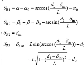
The primary motion of each compliant joint associated with the input motion can be firstly derived as
2 2 in 1 2 in 1 out P2 in P1 in 1 0 0 R2 0 in 1 0 R1 ) ( 1 )) ( sin(arccos ) arcsin( ) arccos( d L d L d L d L L d L d (1)
where θR1 and θR2 is the rotational angles of the compliant
R joints, and δP1 areδP2 is the translational displacement of
the compliant P joints. δin is the input motion from the
linear actuator, and δout is the primary output motion of the
jaw where the bottom-surface center of the motion stage of the P2 joint is specified as the output point of the jaw. The other symbols are the geometrical parameters as indicated in Fig. 1(d).
Using Eq. (1), the amplification ratio between the output displacement and the input displacement is obtained as: LX d d X L 1 2 2 in out 1
(2)
where
L d X 1
in .The linear stiffness of each compliant joint is further obtained as follows [12, 14]:
cos / ) 12 / ( ) 1 3 3 ( 8 ) 12 / ( 24 d 3 2 R2 R1 3 P 3 P2 P1 L UT E K K L UT E K K (3)
where KP1 and KP2 is the translational stiffness of the
compliant P joints and KR1 and KR2 is the rotational
stiffness of the compliant R joints. The other symbols denote the geometrical parameters and material property as indicated in Fig. 1(d).
The use of Eqs. (1) and (2) yields the potential energy of the system with regard to the input displacement:
2 2 2 in 1 P2 2 in 1 0 R2 2 0 in 1 R1 2 in P1 2 out P2 2 R2 R2 2 R1 R1 2 in P1 ] ) ( 1 [ )] arcsin( [ ] ) [arccos( 2 1 2 2 1 2 2 1 2 2 1 2 d L d L K L d K L d K K K K K K U (4) The input force is finally obtained using principle of virtual work [3]:
) 1 ]( 1 [ 2 / ) 1 1 )]( arcsin( [ 2 / ) 1 1 ]( ) [arccos( 2 ) ( 2 2 2 2 2 P2 2 0 R2 2 0 R1 1 P1 in X X d X L K L X X K L X X K LX d K U F (5)
IV. CASE STUDIES
In this section, the two presented designs (Figs. 1(b) and 1(c)) are studied in details. Both designs have the same geometrical parameters for the CPG’s PRBM (Fig. 1(d)) and each compliant joint/module. All these parameters are assigned valued as listed in Tables 1 and 2 for the case studies.
Nonlinear Finite element analysis (FEA) software, Comsol, is used to simulate the two cases with comparison to the analytical model obtained in Section III. Here, we set up the simulation as follows: free 10-node tetrahedral element and extra fine meshing with maximum element size of 10.5 mm and minimum element size of 0.451 mm. The material properties are: Young’s modulus E=69 GPa and yield strength σs=276 MPa. The input displacement is
limited to less than 1mm to ensure that the material deformation is within the yield strength.
TABLE 1.GEOMETRICAL PARAMETERS OF CPG’S PRBM
L 162.688 mm
d1 141.493mm
d2 80.293 mm
α0 29.574°
β0 60.426°
TABLE 2.JOINTS’ GEOMETRICAL PARAMETERS AND MATERIAL PROPERTY
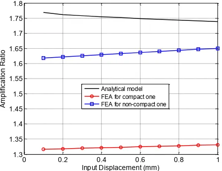
Figures 2 to 6 show the FEA simulation results for the two case studies. It is suggested that the analytical model agrees better with the FEA model of the non-compact CPG (Fig. 1(c)) than that of the compact CPG (Fig. 1(b)). The output of the compact design (Fig. 4) is much smaller than the analytical model as predicted. This is mostly due to the fact that the compact CPG has worse load transmissibility. It is noted that the results in Fig. 4 show that the amplification ratio is not a constant value with slight fluctuation.
T 1 mm
U 10 mm
LR 42.25 mm
LP 40 mm
Ld 40 mm
W 14.50 mm
λ 91.78/42.25
γ 18.78°
E 69 GPa
[image:3.595.320.537.90.229.2] [image:3.595.78.225.133.248.2]However, the compact CPG has better characteristics in its compact configuration (Fig. 1(b)), and smaller parasitic translation and parasitic rotation (Figs. 5 and 6).
[image:4.595.68.290.115.287.2]Figure 2. Relationship between input force and input displacement
Figure 3. Relationship between input displacement and output displacement
[image:4.595.319.538.295.472.2]Figure 4. Relationship between input displacement and amplification ratio
[image:4.595.69.288.320.494.2]Figure 5. Relationship between input displacement and parasitic translation of output point
Figure 6. Relationship between input displacement and parasitic rotation of output jaw
V. FURTHER CONSIDERATIONS
The performance characteristics of the proposed CPG based on the 2-PRRP mechanism not only change with the structure reconfiguration (joint positions) but also are influenced by the geometrical parameters of the PRBM of the PRRP mechanism, compliant joint type, and beam length and thickness. Therefore, more optimization work on selecting the influence factors can be conducted to obtain better performance characteristics. However, the structure reconfiguration is a paramount method to design a CPG.
Alloy can be selected to fabricate the CPG with AL6061-T6 and AL7075-T6 being recommended due to their low internal stresses, good strength and phase stability, and relatively low cost.
The CPG can be fabricated monolithically from a piece of blank plate using the well-known planar manufacturing methods such as CNC multi-axis milling machining, wire electrical discharge machining (wire EDM), and water jet. In order to control the CPG’s two jaws to handle a micro-structure, a PZT actuator can be adopted to produce
0 50 100 150 200 250
0 0.1 0.2 0.3 0.4 0.5 0.6 0.7 0.8 0.9 1
Input Force (N)
In
p
u
t D
is
p
la
ce
m
e
n
t (
m
m
)
Analytical model FEA for compact one FEA for non-compact one
0 0.2 0.4 0.6 0.8 1
0 0.2 0.4 0.6 0.8 1 1.2 1.4 1.6 1.8
Input Displacement (mm)
O
u
tp
u
t D
is
p
la
ce
m
e
n
t (
m
m
)
Analytical model FEA for compact one FEA for non-compact one
0 0.2 0.4 0.6 0.8 1
1.3 1.35 1.4 1.45 1.5 1.55 1.6 1.65 1.7 1.75 1.8
Input Displacement (mm)
A
m
p
lif
ic
a
tio
n
R
a
tio
Analytical model FEA for compact one FEA for non-compact one
0 0.2 0.4 0.6 0.8 1
-0.04 -0.035 -0.03 -0.025 -0.02 -0.015 -0.01 -0.005 0
Input Displacement (mm)
P
a
ra
si
tic
M
o
tio
n
o
f O
u
tp
u
t P
o
in
t (
m
m
)
FEA for compact one FEA for non-compact one
0 0.2 0.4 0.6 0.8 1
-7 -6 -5 -4 -3 -2 -1 0 1x 10
-4
Input Displacement (mm)
P
a
ra
si
tic
R
o
ta
tio
n
o
f O
u
tp
u
t P
o
in
t (
ra
d
[image:4.595.65.289.536.708.2]the input force due to its merits including large force, high stiffness, fast response, compact size and up to nano-positioning displacement control. The compression force on the object grasped by two jaws may be measured by two strain gauges bonded to the two jaws to avoid crushing the micro-structures. In addition, the strain gauge can be used for the sophisticated closed-loop control. A visual assembled prototype incorporating the PZT actuator and strain gauges is shown in Fig. 7.
Figure 7. A visual assembled prototype
VI. CONCLUSIONS
The position space concept has been used in this paper to design new CPGs based on a 2-PRRP mechanism. The structure of compliant mechanisms can be reconfigured based on specific requirements through changing the positions of each compliant module thereof within their position spaces. As a result, two typical CPGs (compact one and non-compact one) have been designed and analyzed using the analytical model and/or nonlinear FEA model.
It has been observed that the analytical model agrees better with the FEA model of the non-compact CPG than that of the compact CPG.
This work provides a solid starting point for further development of CPG for manipulating submillimiter objects.
REFERENCES
[1] SFI report:
http://www.sfi.ie/assets/media/files/downloads/Fundi ng/Funding%20Calls/investigators_programme/IvP% 202014%20full%20description%20of%20themes.pdf [2] EPSRC grant details:
http://gow.epsrc.ac.uk/NGBOViewGrant.aspx?Grant Ref=EP/K018345/1
[3] L.L. Howell, Compliant Mechanisms, New York: John Wiley & Sons, 2001.
[4] L.L. Howell, S.P. Magleby, and B.M. Olsen, Handbook of Compliant Mechanisms, John Wiley & Sons, New York: John Wiley & Sons, 2013.
[5] S. Kota, J. Joo, Z., Li, S.M. Rodgers, and K.
Sniegowski, “Design of compliant mechanisms: applications to MEMS,” Analog Integr. Circ. Sig. Process., vol. 29 (1-2), pp. 7–15, 2001.
[6] M.N.M. Zubir, B. Shirinzadeh, and Y. Tian, “Development of novel hybrid flexure-Based microgrippers for precision micro-object manipulation,” Rev. Sci. Instrum., vol. 80, pp. 065106, 2009.
[7] A. Nikoobin, and H.M. Niaki, “Deriving and analyzing the effective parameters in microgrippers performance,” Scientia Iranica B, vol. 19(6), pp. 1554-1563, 2012.
[8] S.K. Nah, and Z.W. Zhong, “A microgripper using piezoelectric actuation for micro-object manipulation,” Sensor Actuat. A-Phys., vol. 133, pp. 218–223, 2007.
[9] M. Goldfarb, and N. Celanovic, “A Flexure-based gripper for small-scale manipulation,” Robotica, vol. 17, pp. 181–187, 1999.
[10] J.D. Beroz, S. Awtar, M. Bedewy, T. Sameh, and A.J. Hart, “Compliant microgripper with parallel straight-line jaw trajectory for nanostructure manipulation,” Proceedings of 26th American Society of Precision Engineering Annual Meeting, Denver, USA, 2011. [11] A.N. Reddy, N. Maheshwari, D.K. Sahu, and G.K.
Ananthasuresh, “Miniature compliant grippers with vision-based force sensing,” IEEE Trans. Robot., vol. 26(5), pp. 867–877, 2010.
[12] G. Hao, , and X. Kong, “Design and modelling of a self-adaptive compliant parallel gripper for high-precision manipulation,” Proceedings of the ASME 2012 International Design Engineering Technical Conferences & Computers and Information in Engineering Conference (IDETC/CIE 2012), August 12-15, Chicago, IL, USA, 2012.
[13] H. Li, and G. Hao, “A Constraint and position identification (CPI) approach for the synthesis of decoupled spatial translational compliant parallel manipulators,” Mech. Mach. Theory, vol. 90, pp. 59– 83, 2015.
[14] G. Hao, Q. Meng, and Y. Li, “Design of large-range XY compliant parallel manipulators based on parasitic motion compensation,” Proceedings of the ASME 2013 International Design Engineering Technical Conferences & Computers and Information in Engineering Conference, Portland, USA, 2013.
PZT Strain gauge to test pressure
Top layer for gripper