T h e o p e n – a c c e s s j o u r n a l f o r p h y s i c s
New Journal of Physics
Effect of self-generated magnetic fields on
fast-electron beam divergence in solid targets
X H Yuan1,6, A P L Robinson2, M N Quinn1, D C Carroll1,
M Borghesi3, R J Clarke2, R G Evans2,4, J Fuchs5, P Gallegos1,2, L Lancia5, D Neely2, K Quinn3, L Romagnani3, G Sarri3,
P A Wilson3 and P McKenna1,7
1SUPA Department of Physics, University of Strathclyde, Glasgow G4 0NG,
UK
2Central Laser Facility, STFC Rutherford Appleton Laboratory, Didcot,
Oxfordshire OX11 0QX, UK
3School of Mathematics and Physics, Queen’s University Belfast, Belfast BT7
1NN, UK
4The Blackett Laboratory, Imperial College London, London SW7 2AZ, UK 5Laboratoire pour l’Utilisation des Lasers Intenses, Ecole Polytechnique,
91128 Palaiseau, France
E-mail:[email protected]
New Journal of Physics12(2010) 063018 (10pp) Received 26 March 2010
Published 11 June 2010 Online athttp://www.njp.org/ doi:10.1088/1367-2630/12/6/063018
Abstract. The collimating effect of self-generated magnetic fields on fast-electron transport in solid aluminium targets irradiated by ultra-intense, picosecond laser pulses is investigated in this study. As the target thickness is varied in the range of 25µm to 1.4 mm, the maximum energies of protons accelerated from the rear surface are measured to infer changes in the fast-electron density and therefore the divergence of the fast-electron beam transported through the target. Purely ballistic spreading of the fast-electrons would result in a much faster decrease in the maximum proton energy with increasing target thickness than that measured. This implies that some degree of ‘global’ magnetic pinching of the fast-electrons occurs, particularly for thick (>400µm) targets. Numerical simulations of electron transport are in good
6Also at State Key Laboratory of Transient Optics and Photonics, Xi’an Institute of Optics and Precision
Mechanics, Chinese Academy of Sciences, Xi’an 710119, People’s Republic of China.
7Author to whom any correspondence should be addressed.
agreement with the experimental data and show that the pinching effect of the magnetic field in thin targets is significantly reduced due to disruption of the field growth by refluxing fast-electrons.
Contents
1. Introduction 2
2. Experimental results 3
3. Model of sheath evolution and proton acceleration 5
4. Electron transport simulations 7
5. Summary 9
Acknowledgments 9
References 9
1. Introduction
When a high-power laser pulse with irradiance>1018W cm−2µm2interacts with a solid target,
a significant fraction of the laser energy is transferred to the generation of relativistic (fast) electrons. The physics of the transport of the fast-electron beam through the target continues to attract intense interest due to the potential to use electrons to transfer energy from the laser pulse to ignite the compressed fuel in the fast ignition (FI) approach to inertial confinement fusion [1, 2]. The fast-electrons are also responsible for the generation of large space charge fields, which produce and accelerate ions [3].
The divergence (or collimation) of the beam of fast-electrons propagating inside the target is of particular interest as this defines a number of parameters for FI, including the maximum electron source size (hence the laser spot size) and the distance between the electron source and the fuel assembly [4]. Accurate knowledge and control of the fast-electron beam divergence is crucial for a successful demonstration of the electron-based FI scheme and for enhancement of laser-driven ion sources.
When a current of fast-electrons propagates into a solid density plasma, a magnetic field
B is generated according to ∂B/∂t= −∇ ×E= −∇ ×(η· je), where E is the electric field,
je is the fast-electron current density and η is the cold plasma resistivity [5]. This field is azimuthal around the fast-electron beam and gives rise to a ‘global’ pinching effect, which acts to collimate the beam, as described theoretically by Bell and Kingham [6]. Previously, self-generated magnetic fields have been inferred in the work of Tatarakis et al [7] in which plasma jets at the rear side of target foils were observed and recently by Storm et al [8] to explain differences between initial (simulated) and final (measured) fast-electron beam divergence in a solid target (at intensity∼1019W cm−2). However, there is limited experimental
evidence to date on the effectiveness of the field in collimating electrons (in homogeneous solid targets) and on the factors influencing the degree of collimation. In contrast, experimental measurements of Kαemission at the rear surface of metallic targets, typically up to a thickness of ∼100µm, suggest that the fast-electron beam has a significant and constant divergence angle, which increases with laser intensity from (half-angle)∼12◦at 3×10¹⁸W cm−2 to 27◦at
5×10²⁰W cm−2[9].
of multi-MeV proton emission from the rear surface of the target. It is found that the maximum proton energy decreases approximately linearly with the thickness of aluminium targets in the range of 25µm to 1.4 mm. Purely ballistic spreading of the fast-electrons would result in a much faster fall in the maximum proton energy, and this implies that some magnetic pinching of the fast-electrons occurs. The measurements are found to be in good agreement with numerical calculations performed using a 2D hybrid-Vlasov–Fokker–Planck code called LEDA [5], which also show that electron refluxing [10] can disrupt the growth of the collimatingB-field in thin targets.
2. Experimental results
The experiment was performed at the Rutherford Appleton Laboratory using the Vulcan laser, delivering pulses with energy (on the target), EL, up to 280 J, duration,τL, equal to 0.7 ps (full-width at half-maximum (FWHM)) and wavelength equal to 1.053µm. Thep-polarized pulses were focused with anf/3 off-axis parabolic mirror onto target at an incident angle equal to 13◦
with respect to the target normal axis, and to a calculated peak intensity of 6×10²⁰W cm−2.
The laser pulse parameters were fixed throughout the experiment. The targets were 3 mm×
7 mm aluminium foils, with thickness, L, varied in the range of 25µm to 1.4 mm. Passive stacks of 5 cm×5 cm dosimetry film (RCF: Gafchromic© film, HD-810 and MD-V2-55) were positioned 6 cm from the rear of the target (centred on the normal axis to the target) to measure the spatial intensity distribution of the beam of accelerated protons at energies given by the Bragg peak deposition in each piece of film. A 3-mm-wide slot machined in the RCF facilitated a line-of-sight for a Thomson parabola ion spectrometer positioned behind the stack along the target normal axis. Measurements of efficient acceleration of carbon and oxygen ions, sourced from contaminants on the rear surface of the targets, confirm that for the laser and target parameters of this experiment the rear-surface target normal sheath acceleration (TNSA) mechanism [3] dominates.
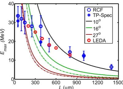
The most salient result of our investigation is the measured decrease in the maximum proton energy, Emax, with increasing L, shown in figure 1 (for which good agreement is found between the RCF and Thomson parabola spectrometer measurements). This measurement differs sharply from what is expected on the basis of simple ballistic transport and what has been reported previously for lower laser pulse energies and intensities [11, 12]. Expected Emax as
a function of L calculated using a simple model based on ballistic transport is also plotted in figure 1. This model consists of the 1D isothermal plasma expansion formulae derived by Mora [13] (which had been successfully applied previously for similar laser and target parameters [11,12,14]), and a variation in the electron density determined by ballistic electron transport through the target at a given constant half-angle of divergence,θ1/2. For the laser pulse
parameters used, θ1/2∼27◦is expected from the work of Greenet al[9]. Calculations for θ1/2
equal to 10◦and 16◦(as inferred in [8]) are also shown for comparison.
For the purpose of the model calculations, it is assumed that 25% of the laser pulse energy is converted into fast-electrons (ηL→e=0.25), with mean electron energykBTe=7.4 MeV, as given by ponderomotive scaling [15]. This is assumed to remain constant with increasing L, which is justified on the basis of electron transport simulation results discussed later. The number of hot electrons generated is determined to be Ne=ηL→eEL/kBTe=6×1013. These
0 300 600 900 1200 1500 0
10 20 30 40
L(µm) E ma
x
(M
eV
)
[image:4.595.148.349.108.254.2]RCF TP-Spec 10o 16o 27o LEDA
Figure 1. Maximum proton energy as a function of target thickness. Blue symbols are measurements made using RCF and a Thomson parabola spectrometer (TP-Spec). The error bars include the variation over multiple shots and the energy resolution. The solid lines correspond to calculations using a plasma expansion model assuming ballistic electron transport at given fixed divergence angles. The dashed lines include a correction due to scattering within the target. The red symbols are the result of plasma expansion calculations using electron densities determined from electron transport simulations using the LEDA code.
1.3τL, as used previously by Fuchset al[12]. Variation of the parametersηL→eandτaccchanges the predicted maximum proton energies, but does not significantly change the overall shape of the predicted Emaxas a function of the L curve and cannot reproduce the measurements.
Adjustments to the plasma expansion model calculations to account for electron scattering from target atoms are also shown in figure 1 (dashed lines). These are estimated using the Monte Carlo code GEANT4 [16]. A group of 8 MeV electrons are propagated through a 2 mm aluminium target and the lateral extent of the scattered electrons is calculated as a function of distance. This has the effect of reducingneand therefore Emax.
0 300 600 900 1200 1500 0 10 20 30 40
L(µm) E ma x (Me V ) Injection1 Injection2 Injection3 RCF TP-spec
-200 0 200
0 2 4 6 8x 10
24
R (µm) n e (/m 3 ) Injection1 Injection2 Injection3
0 10 20 30 40 50 0
10 20 30 40
Electron Energy (MeV)
D iver g ence half a ngl e ( ° ) Injection1 Injection2 Injection3
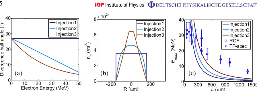
[image:5.595.77.525.87.246.2](a) (b) (c)
Figure 2. (a) Example distributions of injected fast-electron beam divergence with energy. (b) The corresponding electron density distribution at the rear surface of a 300µm-thick target. (c) The resulting maximum proton energies as a function of target thickness as calculated using the Mora plasma expansion formulae. The calculations include the effects of electron stopping in the target.
plasma expansion formula for the densities determined with the three different injected electron distributions (assuming kBTe=7.4 MeV and τacc=1.3τL, as discussed above) are shown in figure2(c). The electron divergence distribution clearly affects the maximum proton energy, but does not account for the nearly linear decrease in Emaxwith Lmeasured.
As clearly shown, the measured dependence of EmaxonL cannot be explained by ballistic transport of fast-electrons through the target at a constant angle of divergence. In order to reproduce the results the electron beam divergence must decrease with increasing L. The implication is that self-generated fields in the target must be reducing the transverse spreading of the beam (particularly in thicker targets). Magnetic collimation is the obvious candidate for this effect.
3. Model of sheath evolution and proton acceleration
To quantify the change in the transverse size of the initial electron sheath (before expansion) with L, the sheath and ion front evolution in space and time are modelled and the resulting ion beam parameters compared to the measurements, using an approach similar to that reported by Carroll et al[19]. The model of the sheath evolution involves three considerations: (i) the initial sheath shape; (ii) the sheath transverse expansion velocity as a function of time; and (iii) the temporal evolution of the magnitude of the sheath electric field. The initial sheath field shape is assumed to be parabolic based on the conclusions of Brambrink et al [20]. We also considered Gaussian and hyperbolic sheath profiles, but find that these do not reproduce the measured proton beam divergence as a function of energy. The initial transverse sheath expansion velocity is set equal to c, as reported in previous work for very similar laser parameters [21, 22], and decreases exponentially with time, with 1/e=1.6 ps, consistent with optical probe reflectometry measurements of Anticiet al[23]. The field strength increases with the rising edge of the laser pulse with a Gaussian profile to a maximum value set by the measured
0 8 16 24 32
30 40 50 60 70
E
p(MeV)
θ
(
°
)
Model RCF
0 300 600 900 1200 0
100 200 300 400 500
L(µm)
D e
(
µ
m
)
Model 10o 16o 27o LEDA
(a) (c)
0 8 16 24 32
0 400 800
E
p(MeV) D p
(
µ
m) Model
[image:6.595.147.536.86.283.2]RCF (b)
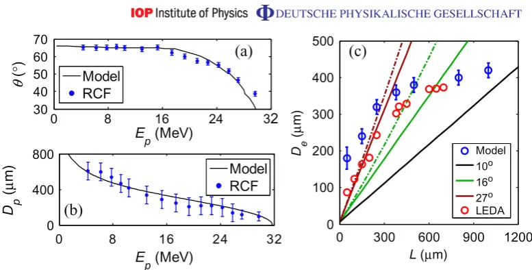
Figure 3. Comparison of (a) proton beam divergence and (b) proton source size as calculated using the sheath expansion model with measurements made by irradiation of a target with linear grooves machined into the rear surface. (c) Initial electron sheath size as a function of target thickness. Blue symbols result from the application of the model to the experiment data. The error bars include the variation over multiple shots and the energy resolution of each piece of RCF film. The solid lines correspond to ballistic electron transport at given fixed divergence angles. The dashed lines include a correction due to scattering within the target. The red symbols correspond to the lateral extent of the fast-electron beam (at the point in time when the fast-electrons reach the rear surface) in 2D LEDA hybrid simulations.
occurs in they-axis) and time(t)can be written as
E(y,t)=E0·H(y,t)·G(t), (1)
where E0 is the peak field strength; H(y,t) and G(t) define the sheath shape and temporal
profile, respectively, and are given as
H(y,t)=1− y 2
4p(t),
where
p(t)=[De/2 +c·(t+ti)exp(−(t+ti)/1.6×10 −12)]2
2 ,
where De is the initial sheath diameter (FWHM in the y-axis), sheath expansion starts at
t = −ti and G(t)=exp(−4 ln(2)t2/τL2) fort 60 (wheret =0 corresponds to the time of the peak field), andG(t)=exp(−t/1.6×10−12)fort >0.
To test the sheath evolution model, the calculated proton source size and divergence as a function of energy are both compared with direct measurements using a 25µm-thick Au target with lines (grooves with separation equal to 10µm and depth equal to 1µm) manufactured into the rear surface [26]. The line structure is mapped onto the measured proton spatial intensity profile and the source size as a function of energy is determined by counting the lines in each RCF layer [26]. As shown in figure 3(b), the calculated proton source size as a function of energy is in excellent agreement with the measurement when De is varied to provide a best fit
to the measured proton beam divergence as a function of energy—figure3(a).
Figure 3(c) shows the resulting De as a function of L. For relatively thin targets
(L <300µm) the increase in De with increasing L is consistent with an approximately
constant divergence angle of ∼27◦. A transition is observed at about 300–400µm, above
which the growth in De with L is much lower than expected from ballistic transport. This reduction in the effective beam divergence in thick targets is likely to result from the pinching effect of the azimuthal B-field resistively self-generated by the fast-electron beam [6].
The growth of the self-generated B-field is governed by the electron beam and target material properties [6] and should be independent of target thickness, particularly as the field is strongest close to the electron source (where the current density is highest). The apparent lack of beam pinching for L<300µm may be related to electron refluxing within the target during the laser pulse duration [10]. Counter-streaming fast-electrons act to locally cancel out the net forward fast-electron current in thin targets, disrupting the growth and therefore the pinching effect of theB-field.
4. Electron transport simulations
If a ‘global’ pinching of the fast-electron beam due to self-generated magnetic fields is responsible for the reduction in the transverse extent of the fast-electron population in thick targets, then this should be apparent in numerical simulations. The 2D hybrid-Vlasov–Fokker–Planck code called LEDA was used to carry out a set of fast-electron transport simulations to investigate this.
The code is described in detail elsewhere [5]. The fast-electrons are injected at the left-hand end of the grid, in a pulse with duration equal to 0.7 ps. The fast-electron distribution is a relativistic Maxwellian of the form(cosMθ)p2exp(−(p2+m2ec2)1/2/kBTe), withkBTe=9 MeV.
We note that this is slightly higher than the temperature of the fast-electron distribution expected in the experiment. However, comparative example simulation runs with kBTe=7.4 MeV show
that this small temperature difference does not significantly affect the simulation results (nor the conclusions of this work). The injection angle is set atM =8 (≈24◦half-angle). The conversion
efficiencyηL→e=0.25 and the initial background temperature is set to 1 eV. A uniform spatial grid is used for all the simulation runs, with a cell size equal to 1µm. The number of cells in
yis typically 480, and the cell number inxis varied between 80 and 800, to simulate the variation in L. All other parameters are fixed.
(a) (b)
(c) (d)
0 100 200 300 -150
-50 50 150
L=300µm
x(µm)
y
(
µ
m)
40 80 -150
-50 50 150
L=80µm
x(µm)
y
(
µ
m)
-2000 0 2000
0 25 50 75 100 1
10 100 1000
E
e(MeV)
Number of electrons
(arb. units)
0 300 600 900 0
5 10 15x 10
25
L(µm)
n e
(m
[image:8.595.147.458.91.371.2]-3 )
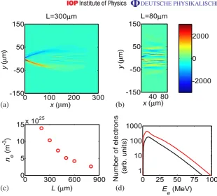
Figure 4. Fast-electron transport simulation results using the LEDA code: the magnetic flux density (in Tesla) for a target thickness of (a) 300µm and (b) 80µm, at 1.4 ps after the laser pulse interaction (atx =0,y=0). (c) Temporally averaged fast-electron density at the rear surface of the target as a function of target thickness. (d) Electron spectrum on-axis (y=0) at the rear surface for
L=400µm (red) and 800µm (black).
through the thinner target and the resulting B-field is considerably fragmented, reducing its effectiveness in collimating electrons.
Two main parameters of interest are extracted from the results of the main simulation runs. The first is the average fast-electron density on-axis (y=0) at the rear surface of the target, which is plotted in figure4(c) as a function ofL. A change in the rate of decrease is observed at
L ≈400µm. These values ofneare used with the Mora [13] plasma expansion formulae (with
the same assumptions and input parameters discussed above) to calculate Emax. The results are found to be in excellent agreement with the experimental results, as shown in figure 1. The second parameter extracted is the lateral extent (full-width) of the beam of fast-electrons as they reach the target rear surface and before any reflection has occurred (the simulation output time at which the distribution is sampled increases with L accordingly). As shown in figure 3(c), although smaller than the initial sheath size extracted from the sheath evolution model fit to the experimental data, a similar overall increase in sheath size with L is observed, including the differences between thinner and thicker targets.
As mentioned previously, one of the assumptions implicit in this work is that the fast-electron temperature at the target rear surface does not change significantly with L. The results of the LEDA simulation runs confirm that this assumption is valid, as shown in figure 4(d) by the two example electron spectra sampled on-axis at the target rear surface for L =400 and 800µm. The fast-electron density is reduced for the thicker target, but a significant change in
kBTe is not observed.
5. Summary
In summary, we report on an experimental investigation of the effect of magnetic collimation on fast-electron transport using measurements of multi-MeV proton emission. A key advantage of this novel diagnostic approach is that it is directly sensitive to the density of fast-electrons at the target rear surface. Using this approach we obtain evidence that some magnetic pinching of the fast-electron beam occurs in thick metallic targets. The results are found to be in good agreement with fast-electron transport simulations, which further show that fast-electron refluxing within thin targets disrupts the field growth.
A detailed assessment of the implications of these results for FI is beyond the scope of this paper. However, we briefly consider two points. Firstly, FI is likely to require laser pulses with duration between 5 and 10 ps and intensity ∼3×10¹⁹W cm−2 to produce electrons with
kBTe≈1.2 MeV [4]. According to the Bell–Kingham criteria [6] the degree of self-collimation
increases both for longer pulse duration and lower electron temperature. Secondly, the FI fuel target has a low effective Z, which may reduce the magnitude of the self-generatedB-field [6]. A detailed investigation of the scaling of the self-generated field and resulting electron beam collimation to FI conditions is the subject of further work.
Acknowledgments
We acknowledge the staff of the Central Laser Facility for expert support and STFC’s e-Science facility for permission to use their computing resources. We also thank Dr R Martin for his help in using the PCRI computer cluster at the University of Strathclyde and Dr M P Desjarlais for stimulating discussions. This work was supported by EPSRC (grant number EP/E048668/1) and the EU COST P-14 Action.
References
[1] Freeman R R, Batani D, Baton S, Key M and Stephens R 2006 The generation and transport of large currents in dense materials: the physics of electron transport relative to fast ignitionFusion Sci. Technol.49297–315 [2] Tabak M, Hammer J, Glinsky M E, Kruer W L, Wilks S C, Woodworth J, Campbell E M, Perry M D and
Mason R J 1994 Ignition and high gain with ultrapowerful lasersPhys. Plasmas11626–34
[3] Wilks S C, Langdon A B, Cowan T E, Roth M, Singh M, Hatchett S, Key M H, Pennington D, MacKinnon A and Snavely R A 2001 Energetic proton generation in ultra-intense laser–solid interactionsPhys. Plasmas 8542–9
[4] Honrubia J J and Meyer-Ter-Vehn J 2009 Fast ignition of fusion targets by laser-driven electronsPlasma Phys. Control. Fusion51014008
[6] Bell A R and Kingham R J 2003 Resistive collimation of electron beams in laser-produced plasmasPhys. Rev. Lett.91035003
[7] Tatarakis M, Davies J R, Lee P, Norreys P A, Kassapakis N G, Beg F N, Bell A R, Haines M G and Dangor A E 1998 Plasma formation on the front and rear of plastic targets due to high-intensity laser-generated fast-electronsPhys. Rev. Lett.81999–1002
[8] Storm M et al2009 High-current, relativistic electron-beam transport in metals and the role of magnetic collimationPhys. Rev. Lett.102235004
[9] Green J Set al2008 Effect of laser intensity on fast-electron-beam divergence in solid-density plasmasPhys. Rev. Lett.100015003
[10] Sentoku Y, Cowan T E, Kemp A and Ruhl H 2003 High energy proton acceleration in interaction of short laser pulse with dense plasma targetPhys. Plasmas102009–15
[11] Kaluza M, Schreiber J, Santala M I K, Tsakiris G D, Eidmann K, Meyer-ter-Vehn J and Witte K J 2004 Influence of the laser prepulse on proton acceleration in thin-foil experimentsPhys. Rev. Lett.93045003 [12] Fuchs J et al2006 Laser-driven proton scaling laws and new paths towards energy increaseNat. Phys.2
48–54
[13] Mora P 2003 Plasma expansion into a vacuumPhys. Rev. Lett.90185002
[14] Robson Let al2007 Scaling of proton acceleration driven by petawatt-laser–plasma interactionsNat. Phys. 358–62
[15] Wilks S C and Kruer W L 1997 Absorption of ultrashort, ultra-intense laser light by solids and overdense plasmas: optics of relativistic electronsIEEE J. Quantum Electron.331954–68
[16] Agostinelli S, Allison J, Amako K, Apostolakis J and Araujo H 2003 Geant 4—a simulation toolkitNucl. Instrum. Methods Phys. Res.A506250–303
[17] Berger M J, Coursey J S, Zucker M A and Chang J 2005Stopping-Power and Range Tables for Electrons, Protons, and Helium Ions(Gaithersburg, MD: National Institute of Standards and Technology)
[18] Honrubia J J, Antonicci A and Moreno D 2004 Hybrid simulations of fast-electron transport in conducting mediaLaser Particle Beams22129–35
[19] Carroll D C et al 2007 Active manipulation of the spatial energy distribution of laser-accelerated proton beamsPhys. Rev.E76065401
[20] Brambrink E, Roth M, Blazevic A and Schlegel T 2006 Modeling of the electrostatic sheath shape on the rear target surface in short-pulse laser-driven proton accelerationLaser Particle Beams24163–8
[21] McKenna P et al 2007 Lateral electron transport in high-intensity laser-irradiated foils diagnosed by ion emissionPhys. Rev. Lett.98145001
[22] Quinn Ket al2009 Laser-driven ultrafast field propagation on solid surfacesPhys. Rev. Lett.102194801 [23] Antici Pet al2008 Hot and cold electron dynamics following high-intensity laser matter interactionPhys.
Rev. Lett.101105004
[24] Kar Set al2008 Dynamic control of laser-produced proton beamsPhys. Rev. Lett.100105004
[25] Hegelich Met al 2002 MeV ion jets from short-pulse-laser interaction with thin foilsPhys. Rev. Lett. 89
085002