City, University of London Institutional Repository
Citation
:
Bloomfield, R. E. and Netkachova, K. Building Blocks for Assurance Cases.
Paper presented at the International Symposium on Software Reliability Engineering
(ISSRE), 03-11-2014 - 06-11-2014, Naples, Italy.
This is the accepted version of the paper.
This version of the publication may differ from the final published
version.
Permanent repository link:
http://openaccess.city.ac.uk/5121/
Link to published version
:
Copyright and reuse:
City Research Online aims to make research
outputs of City, University of London available to a wider audience.
Copyright and Moral Rights remain with the author(s) and/or copyright
holders. URLs from City Research Online may be freely distributed and
linked to.
City Research Online:
http://openaccess.city.ac.uk/
publications@city.ac.uk
Building Blocks for Assurance Cases
Robin Bloomfield, Kateryna Netkachova
City University London and Adelard LLP London, UK
{R.E.Bloomfield, Kateryna.Netkachova.2}@city.ac.uk {reb, kn}@adelard.com
Abstract— The paper introduces an approach to structuring assurance cases using specially-designed CAE building blocks. The blocks are derived from an empirical analysis of the real case structures and can standardise the presentation of assurance cases by simplifying their architecture. CAE building blocks might also increase the precision and efficiency of the claims in arguments and can be used as self-contained reusable components of formal and semi-formal assurance cases.
Keywords— claims, argument, evidence; CAE building blocks; argument strategies; assurance cases
I. INTRODUCTION
Claims, Arguments and Evidence (CAE) has been in use for many years for reasoning and communicating about safety and assurance [1][2]. Various approaches have been proposed to increase rigour and confidence in cases [3][4][5]. The solution we are developing will provide a set of resources for using CAE to support authors of assurance cases. This paper focuses on one of these resources – CAE building blocks.
[image:2.595.43.280.541.707.2]We describe the CAE resources we are developing in terms of a stack (Fig. 1). At the bottom of the stack is guidance on the basic concepts of claims, arguments and evidence. At the next level up in the stack, we define certain combinations of CAE that form the basic building blocks of the approach. These blocks can be then combined into fragments of cases, where it is possible to define typical structures and templates that could be used in a particular class of problems. The templates and exemplars support the development of the overall safety or assurance cases, which should provide a technically-based narrative of the assurance.
Figure 1. Schematic of the CAE stack.
We loosely use a words/sentences and grammar/ paragraphs/narrative stories metaphor to illustrate the approach (see the right side of Fig. 1). Claims, arguments, evidence are small units of cases – just like single words that are the smallest distinct meaningful elements of speech or writing. Words are used together to form a sentence by following specific grammar rules. If the rules are applied correctly, the resulting sentences will be well-formed. Similarly, the claims, arguments and evidence are combined together by using the proposed building blocks (‘rules’) to obtain the correct and well-formed block instances (‘sentences’).
This paper is structured in the following way. A brief introduction into the CAE approach is provided in Section II. Then CAE building blocks, which are the main focus of this paper, are defined and discussed in detail: the concept of CAE building blocks is introduced in Section III, the collection of basic blocks with their description is provided in Section IV and some initial guidance on using the blocks is given in Section V. The concluding remarks and future directions are outlined in Section VI.
II. CLAIMS,ARGUMENTS,EVIDENCE
A. Background and basic concepts
Over the past ten years there has been a trend towards an explicit claim-based approach to safety justification and considerable work has been done on the structuring of safety arguments [1][7][8][9][10]. The approach used here is a CAE approach with the following key elements:
• Claims – assertions put forward for general acceptance. They are typically statements about a property of the system or some subsystem. Claims that are asserted as true without justification become assumptions and claims supporting an argument are called subclaims.
• Evidence that is used as the basis of the justification of the claim. Sources of evidence may include the design, the development process, prior field experience, testing, source code analysis or formal analysis.
In order to support the use of CAE, a graphical notation ASCAD [1] is used to describe the interrelationship of the claims, argument and evidence. In addition to the graphical presentation, there is important narrative and analyses explaining and detailing the claims and arguments being made. Narrative is an essential part of the case and tools such as the Adelard ASCE tool [12] explicitly support it. In the next section we briefly discuss the balance between formality and informality in the use of this notation.
B. Balancing the formal and informal
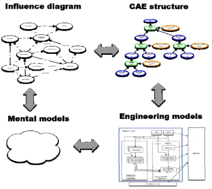
The CAE approach supports the creative process of architecting a safety or assurance case. The development of the case can be seen in terms of moving around the nodes of Fig. 2. We might express our initial thoughts for the safety justification or assurance case informally in terms of arrows and circles as an influence diagram, showing, as the name suggests, the various factors that might influence the property we are reasoning about. As we develop our understanding, we move towards defining more precise claims and arguments and a clearer view of potential evidence. Our understanding can be informed by a variety of engineering models that underpin these claims: we need to know what the claim is about and we need to be able to reason about properties of the system. As the claims become more precise, we relate them to these engineering models to give them semantics. In addition, the CAE structure needs to be more detailed and rigorous and the claim decompositions carefully justified, reflecting the principle that the more onerous the claims are for a system, the more precision and rigour is needed in how they are justified.
[image:3.595.58.267.501.687.2]Despite the experience and existing approaches referred to above, the practice of how to structure and present cases is very varied. In this research we have reviewed many cases, from different industries, and found a wide range of styles and expressiveness. The cases reflect different trade-offs and stages of development and also reflect the lack of guidance on structuring. The wide variety of approaches makes it difficult to compare cases, hard to provide a more rigorous semantics and hard to provide exemplar cases.
Figure 2. Development of a justification – from informal mental model to structured models.
To address the aforementioned issues and provide a more rigorous approach to architecting cases, we have defined specific rules that restrict the type of CAE structures and developed a collection of CAE building blocks.
III. THE CONCEPT AND DEFINITION OF CAE BLOCKS
CAE building blocks are a series of archetypal CAE fragments. They are based on the CAE normal form, which is a standardised structure that we defined for combining claims, arguments and evidence with further simplification and enhancements. One enhancement is to how we address arguments. In CAE an argument is the way in which we explore, given the evidence and assumptions, whether a claim might be true. As discussed above, an argument is initially defined as Toulmin’s warrant [11].
However, we extend this in a number of ways by analysing the proposed warrant to identify those aspects of the argument that allow us to logically show that the claim is valid. We call these aspects of the warrant “side-warrants”. Side-warrants tell us why we can deduce the top-level claim from the subclaims, and under what circumstances the argument is valid, in such a way that the correctness of each argument could be decided more easily. We require arguments to be both logical and explanatory: we require the reasoning to provide us with sufficient understanding of the case that is being made.
The side-warrant is in fact a type of claim and we may wish to challenge and demonstrate this for the specific case. We could do this either by introducing sub-claims that the analysis is indeed worst-case or by justifying the side-warrant directly. The side-warrants can then be supported either by further decomposition, or by narrative argument: in Toulmin’s terminology backing may be introduced to justify the general validity of the warrant to support the specific application of it in the argument being discussed.
The basic scheme of a generic CAE block structure is shown in Fig. 3 below. It shows n subclaims supporting an argument that justifies a top-level claim, with some of the key properties of the argument expressed as the side-warrant and supported by the system information and external backing.
Claim
Subclaim n Subclaim 2
Argument
Subclaim 1
-Side warrant
System information
External backing
Figure 3. General CAE Block Structure.
[image:3.595.307.563.513.631.2]modus ponens)1 but pushes the justification into that for the warrant. Or we may find that if a property referenced in the subclaims distributes then we can infer C1 from the subclaims.
W Claim C1
Argument A
[image:4.595.48.231.94.213.2]Sublaim C12 Sublaim C11
Figure 4. Simple example of CAE fragment with side-warrant.
The side-warrant reminds us of the reasoning we are claiming is true of the block. This may prompt us to detail further the CAE structure as breaking it into more steps may identity how we can make the justification valid. Or it may be that the block is a simple one (perhaps C1 is just the conjunction of C11 and C12). Alternatively it may be that we can appeal to some general result or authority to justify the side-warrant.
The overall justification for the block and its application can be included in the argument node narration or accompanying text for the block. As shown in Fig. 3, both the argument node and the side-warrant can be supported by additional data: system information and external backings. The former includes any system related information that drives the justification: models of system objects and properties, information from the product specification or user documentation, etc. The latter includes facts, guidance, theorems, theories that are appealed to as true statements of facts external to the warrant. The warrant might rely on external backing when demonstrating the claim, so if the backing itself is questionable, it must be justified separately prior to being used in the warrant.
Side-warrant, system information and external backings elements are optional and can be omitted when they are considered unnecessary, although the block will still need justifying. We can therefore deploy CAE blocks with different balances between the graphical and textual, and between the formal and informal reasoning.
IV. THE COLLECTION OF BASIC CAE BUILDING BLOCKS
So far we have identified five basic CAE building blocks. The structure and description of these blocks are provided in this section. The blocks are derived from an empirical analysis of what is trying to be expressed in real cases. We reviewed the structure of a wide range of real cases from the defence, medical, financial and nuclear sectors concerning, for example,
1We have experimented with a number of logical semantics for the CAE
notation, a simple one comes from propositionalising the claims and the warrant so: C11 /\ C12 /\ W => C1
command and control, training systems, smart devices and weapons safety. We believe the resulting set of blocks is sufficiently powerful to capture the majority of what is to be expressed.
A. Decomposition block
A decomposition block is used to claim that a conclusion about the whole object, process, property or function can be deduced from the claims or facts about constituent parts.
More formally, this block is used to show that property P(X) of object, function or process X can be demonstrated by reference to properties P1(X1)⋀ P2(X2)⋀…⋀Pi(Xn) of its
sub-objects X1, X2,…, Xn from which it is composed. The
sub-objects can be artefacts, processes, environments, configurations, functions, organisations etc.
For example, we may claim that if a property holds for each sub-system of a system in a given environment and configuration, then the property holds for the system as a whole in that environment and configuration.
Decomposition block is concerned with the structure. Many claim decompositions are about partitioning some aspect of the claim, for example, according to the functions of the system, the architecture, the properties being considered, or with respect to some sequence such as lifecycle phases or modes of operation.
The basic idea is very simple: in many cases in order to make a claim about a property of an object, we need to investigate whether the object has this property by evaluating its components. To do this, we need to be clear about what the property is and we also need rules about how we view the object as being composed of components and how the properties of these components can be combined (e.g., how reliability properties of components are combined when the degree of independence is not known).
Double decomposition is the most general form in which a claim that a property of an object can be deduced from the other properties of the constituting sub-objects. Single decomposition is when either the property or the object is being decomposed, not both. A general example of single object decomposition is shown in Fig. 5.
P(X)
(P(X1) /\ P(X2) /\ ... /\P(Xn) = P(X1+X2+...+Xn)) /\
(X=X1+X2+...+Xn) Decomposition
P(X1) P(X2) - - - P(Xn)
[image:4.595.306.556.536.653.2]It is important not to forget the mechanisms that combine the elements together, when decomposing into sub-objects or sub-properties.
The side-warrant justifying the decomposition should demonstrate that the object X is composed of X1 to Xn and the property P distributes over the composition. Note that Xn should include the composition mechanism itself.
B. Substitution block
Another common type of claim expansion involves transforming a claim about an object into a claim about a similar object, which can be viewed as a form of substitution.
Substitution block is used to claim that if a property holds for one object, then it holds for an equivalent object. Similarly, if one property holds for an object then an equivalent property may also hold for the same (or equivalent) object. The nature of this “equivalence” will vary with the object and property and will need to be defined.
The structure of the block is shown in Fig. 6 below. It is presented in its most general form where either or both property and object can be shown to equivalent.
Substitution block uses an argument from analogy to infer the conclusion. The similarities of objects or properties form the basis for analogical inference and should be clearly communicated and justified in the side-warrant. More formally, the block is used to deduce P(X) from Q(Y), when Q(X) is equivalent to P(Y) in a particular context, where P and Q are properties of objects X and Y respectively.
A common application of this block is to claim that if a property holds for one object, it holds for another object. For example, we might claim that the evaluated system has a certain property, and therefore the production system has this property too, providing that the production system is equivalent in some clearly defined way to the evaluated one.
Another example is when we have demonstrated a property on a design (e.g. does not deadlock) and we can show that the design model analysed by the tool is equivalent to the actual design (e.g. is a correct abstraction and functionality that has been omitted does not impact the deadlock property).
P(X)
Q(Y)
Substitution Q(Y) is equivalent
[image:5.595.364.499.247.379.2]to P(X)
Figure 6. Object and property substitution.
It should be noted that justifying the equivalence between objects or properties is not a straightforward task and it can be a fallacy to argue from the specific to the general. So the substitution block should be used carefully and the side-warrant will itself usually need elaborating into a substantial argument. Making the side-warrant explicit and demonstrating it separately is one of the advantages of this block.
C. Evidence incorporation block
Evidence incorporation block is used at the edge of the case tree to incorporate the evidence elements. The block demonstrates that a sub-claim is directly satisfied by its supporting evidence.
The basic structure of the block is shown in Fig. 7. A property P(X) of object X is justified directly from the contents of R, where R are accepted facts.
P(X)
evidence incorporation
Results R
P(X)
[image:5.595.78.244.525.685.2]Results R
Figure 7. Forms of evidence incorporation block.
As with other blocks, the use of the argument node is to provide a justification for why the evidence can directly show the claim. If this is deemed unnecessary due to the closeness of the claim and the evidence, then the alternative form shown in the right hand side might be used.
D. Concretion
Concretion block is significantly different from the other blocks: it is used when a claim needs to be given a more precise definition or interpretation and may break the formal reasoning from the lower claims to the top-level claims. It represents an important part of many cases where un-interpreted claims are being given a meaning or claims become operationalised into forms that can be shown to be satisfied.
The general structure of the block is shown in Fig. 8 below.
P(X)
Concretion
P1(X1)
P := P1, X := X1
[image:5.595.349.517.585.700.2]The top claim P(X) is concreted into a more precise claim P1(X1) by defining P as P1, and X as X1. The concretion can apply to the environment, the system, the configuration or the property.
This block is used when a general object, function, process or property can be defined in terms of a more specific way in a particular context. For example, if the top claim about some system attribute is too vague to be demonstrated by a convincing argument that it is valid, it might be transformed and expressed in more measurable less abstract terms. This transformation from something vague to something more precise is called “concretion”, hence the block name.
The concretion block is different from the substitution block: substitution is arguing by analogy using some similarities of objects or properties, concretion argues by interpretation, giving something a meaning rather than by analogy.
Because the use of concretion may break the formal reasoning from the lower claims to the top-level claims, it should always be clearly identified.
E. Calculation block
Calculation block is used to claim that the value of a property of a system in a given environment and configuration can be computed from the values of related properties of other objects in that environment and configuration.
For example, we might argue that the average time of data retrieval from a database can be calculated from the probability that the data is in the cache (a property of one sub-system) and the time of data retrieval if it is not in the cache (a property of the other sub-system).
Fig. 9 shows the general structure of the calculation block assuming the environment E and configuration C of the system X are the same for all claims (defined outside of the block). In the figure Q, Q1, Q2,…, Qi, are properties of objects X, X1, X2, …, Xi, with values a1 to ai, andb is a property/value that is
computed (deduced/calculated) from the a values. The value of Q(X, E, C) can be deduced from the values of Q1(X1, E, C) to Qi(Xi, E, C) using the function or formula F.
-Calculation/Proof b = F(a1, a2, ..., ai)
Q(X, E, C) = b
[image:6.595.37.289.524.675.2]Qi(Xi, E, C) = ai Q1(X1, E, C) = a1 Q2(X2, E, C) = a2
Figure 9. Structure of the calculation block.
Calculation block is used when a claim contains some numerical value of a property that can be calculated from a set of other values of related properties of the system in the same environment and configuration. For example, we might make a claim about the average availability of system based on the subclaims about the system’s failure rate and recovery time values.
Calculation could also be seen as a composite block combining a decomposition block in which the properties have values with a substitution block.
V. USING AND SELECTING BLOCKS
A. Combining blocks
In practice, some of the basic blocks are often merged together into composite blocks. In such situations, it may not always be obvious which basic patterns have been applied, expanding the structure further into a more detailed case could help us understand the underlying logic and see which basic blocks have been applied.
We have identified a few common composite blocks that are used in practice. These are:
• Substitution + decomposition. This composite block is used when a claim about an object is decomposed into a set of claims about an equivalent object. In a more detailed case one could use a substitution block to replace one object or property with another object or properties first, and then apply the decomposition block to partition some aspect of the new claim.
• Concretion + decomposition. This composite block is used when some aspect of the claim is given a more precise interpretation and some aspect of the new claim is partitioned at the same time.
• Any basic block + evidence incorporation. To keep the case concise, evidence nodes are often incorporated right away when applying a basic block. In that case the justification showing why the evidence directly supports the claim is provided in the argument node of the basic block used.
In the block definitions, we talk about an object, such as a system. Sometimes, we may wish to make the environment and configuration explicit but otherwise we may keep them implicit to make the case easier to read. Similarly, we have not made confidence or trust explicit. When we make a claim, confidence is implicit. If we wish to make it explicit, each property could have a confidence value: we would then need a calculus for devising and propagating confidence values: an active research topic in its own right
B. Applying blocks
The CAE blocks are currently being applied within a number of applied research projects including the EU Harmonics project. As indicated in the introduction we are making more detailed resources available [13] and hope to report on their more general application at a later date.
VI. CONCLUSIONS
In this paper we have introduced some Building Blocks for Assurance Cases. The blocks are derived from an empirical analysis of real cases and can standardise the presentation of assurance cases by simplifying their architecture. CAE blocks increase the precision and efficiency of the claims in arguments because each claim instantiated from a block inherits a formal representation as part of the block. This can turn blocks into reusable, self-contained components that could become the main building blocks of formal and semi-formal assurance cases. Furthermore, the way the blocks are structured facilitates the challenge and formal verification of their correct application and stresses the validation with respect to the real world.
The paper does not address the detailed deployment of the CAE blocks, nor does it describe how to challenge cases – a crucial part of gaining confidence in them. We also envisage domain specific versions of the CAE blocks and templates and are developing these for statistical testing, static analysis and security informed safety. In parallel we are developing the Adelard ASCE tool to directly support the implementation of the CAE blocks.
ACKNOWLEDGMENT
Many people and projects have contributed to the approach described, including: Peter Bishop, Sofia Guerra, Dan Sheridan, Robert Stroud. We would like to acknowledge support from the Swedish Nuclear Regulator (Strålsäkerhetsmyndigheten), the EU Harmonics project and the Artemis JU SESAMO project (project number 295354).
The views expressed in this paper are those of the authors and do not represent the views of any sponsors.
REFERENCES
[1] R. E. Bloomfield, P. G. Bishop, and C. C. M. Jones, P. K. D. Froome, “ASCAD – Adelard safety case development manual,” London, 1998. [2] ISO/IEC 15026-2:2011, “Systems and software engineering — Systems
and software assurance, Part 2: Assurance case,” 2011.
[3] R. Hawkins, T. Kelly, J. Knight, P. Graydon, “A New Approach to creating Clear Safety Arguments,” Proc. 19th Safety Critical Systems Symposium (SSS 2011), p. 3-23. Springer, London (2011)
[4] B. Littlewood, D. Wright, “The use of multilegged arguments to increase confidence in safety claims for software-based systems: A study based on a BBN analysis of an idealized example,” IEEE Transactions on Software Engineering, 33(5), pp. 347-365. doi: 10.1109/TSE.2007.1002
[5] E. W. Denney, G. J. Pai, “A Formal Basis for Safety Case Patterns,” 32nd International Conference on Computer Safety, Reliability and Security (SAFECOMP 2013), LNCS 8153, pp. 21-32. Sep. 2013. [6] T. Kelly, J. McDermid, “Safety case patterns-reusing successful
arguments,” IEE Colloquium on Understanding Patterns and Their Application to System Engineering, 1998.
[7] P. G. Bishop, R. E. Bloomfield, “The SHIP safety case - a combination of system and software methods,” SRSS95, Proc. 14th IFAC Conf. on Safety and Reliability of Software-based Systems, Brugge, Belgium, 12-15 September 1995.
[8] P. G. Bishop, R. E. Bloomfield, “A methodology for safety case development,” F. Redmill, T. Anderson (eds.) Industrial Perspectives of Safety-critical Systems: Proc. 6th Safety-Critical Systems Symposium, Birmingham 1998, pp. 194–203, Springer, 1998.
[9] T. Kelly, "The goal structuring notation-a safety argument notation," Proc. DSN 2004 Workshop on Assurance Cases, 2004.
[10] S. Wilson, P. Kirkham, "SAM user manual," University of York, December 1995.
[11] S. E. Toulmin, “The uses of argument,” Cambridge University Press, 1958.
[12] Adelard LLP, “Assurance and Safety Case Environment (ASCE),”
http://www.adelard.com/web/hnav/ASCE/index.html