A REPAIR AND OVERHAUL METHODOLOGY FOR 4
STROKE GASOLINE ENGINE
MOHD KAMIL BIN CHE MAT
B071110384
UNIVERSITI TEKNIKAL MALAYSIA MELAKA
A REPAIR AND OVERHAUL METHODOLOGY FOR 4
STROKE GASOLINE ENGINE
This report submitted in accordance with requirement of the Universiti Teknikal Malaysia Melaka (UTeM) for the Bachelor of Mechanical Engineering Technology
(Automotive Technology) (HONS.)
By
MOHD KAMIL BIN CHE MAT B071110384
900710-11-5659
DECLARATION
I hereby, declared this report entitled “A repair and overhaul methodology for 4 stroke gasoline engine” is the results of my own research except as cited in references.
Signature :
Author’s Name : MOHD KAMIL BIN CHE MAT
APPROVAL
This report is submitted to the Faculty of Engineering Technology of UTeM as a partial fulfillment of the requirements for Bachelor of Mechanical Engineering Technology (Automotive Technology) (HONS.). The member of the supervisory is as follow:
ABSTRAK
Tujuan kertas kerja ini adalah untuk membentangkan pembaikan dan baik pulih metodologi untuk 4 lejang petrol. Metodologi baik pulih untuk setiap kenderaan adalah berbeza. Ini juga bergantung kepada sistem transmisi dan enjin mereka. Ini kerana setiap jenis enjin mempunyai sistem operasi yang berbeza dan mempunyai kod enjin sendiri. Sebagai contoh jenis enjin adalah VTEC oleh Honda, VVTi oleh Toyota, MIVEC oleh Mitsubishi dan sebagainya. Kerosakan yang boleh memendekkan hayat enjin melalui baik pulih enjin kaedah yang salah dan yang akan memberi kesan kepada prestasi dan jangka hayat enjin. Sebagai memasang seperti bolt dengan keperluan tork salah, memasang tali pinggang masa dengan kedudukan yang salah dan sebagainya. Dalam projek ini, pengesahan daripada bahagian-bahagian enjin 4g15 adalah untuk mendapatkan data daripada bahagian-bahagian-bahagian-bahagian enjin sebelum dan selepas baik pulih enjin. Ini adalah untuk memastikan sama ada enjin perlu pembaikan atau tidak.
ABSTRACT
The purpose of this paper is to present a repair and overhaul methodology for 4 stroke gasoline engine. The overhaul methodology for every vehicle is different. This also depends on their transmission and engine systems. This is because each type of engines has different operating systems and has engine code itself. As an example of the type of engine is VTEC by Honda, VVTI by Toyota, MIVEC by Mitsubishi and so on. The damages that can shorten the life of the engine through wrong overhaul engine methodology and that will be give the effect to the performance and the life span of the engine. As such install the bolts with wrong torque need, install the timing belt with the wrong position and so on. In this project, the verification of the 4g15 engine parts is to get the data of engine parts before and after the engine overhaul. This is to ascertain whether the engine needs repairs or not.
DEDICATION
Grateful to ALLAH s.w.t for giving me the strength and health to complete bachelor degree project.
To my beloved parents and family:
Thank you for thanks for the support and assistance given me throughout the process of preparing this thesis. I am proud to have parents and family who care about my life though always far away. May Allah s.w.t bless you all.
ACKNOWLEDGEMENT
I would like to thank to my beloved parents who gives nonstop support and encouragement praying for my success in my life which I am now able to complete my bachelor degree project successfully. Without them, I am nobody to this world which I am very much grateful for having such a wonderful mother, father and brothers that help me all the time.
Secondly, I would like to thanks my bachelor degree project supervisor, Mrs Adnan bin Katijan who teach me well and give more than enough knowledge I could regarding my project and the subject course ever since I step into University Teknikal Malaysia Melaka.
Next would be my lecturers and teaching engineer who gives their very best and support in order for me to be able to compete with others with engineering knowledge has been a great memory for the rest of my life. Thank you so much to them and I will use the knowledge and wisdom that has been told to for the rest of my life.
Lastly, I would like to thanks to my friends and my classmates that helps me and teach me to understand more of the information and technical knowledge for me to complete my project and help me with studies. Without them, I would also be lost from my study year here.
TABLE OF CONTENT
Abstrak i
Abstract ii
Dedication iii
Acknowledgement iv
Table of Content v
List of Tables viii
List of Figures ix
List Abbreviations x
CHAPTER 1: INTRODUCTION 1
1.1 BACKGROUND OF STUDY 1
1.2 PROBLEM STATEMENT 1 1.3 PROJECT OBJECTIVES 2 1.4 WORK SCOPE 2 CHAPTER 2: LITERATURE REVIEW 7
2.0 THEHISTORY OF AUTOMOTIVE ENGINE 3 2.1 THE CONCEPT OF THE 4 STROKE ENGINE 3 2.2 THE TYPE OF FUEL INJECTION SYSTEMS 4 2.3 THE BASIC ENGINE PARTS 5 2.4 ENGINE MECHANICAL DIAGNOSIS 9 2.4.1 DIAGNOSING EXCESSIVE OIL COMSUMPTION 2.4.2 DIAGNOSING OIL PRESSURE PROBLEMS 10
2.4.2.1 CHANGE OIL/TEAT PRESSURE 11
2.5 THE CHASSIS DYNAMOMETER 12
2.6 ENGINE MAINTANCE 13
2.6.1 ENGINE OIL 13
2.6.1.1SELECTION OF OIL 14
2.6.2 ENGINE COOLANT 14
2.6.3 BATTERY 14
2.6.3.1 CHECKING BATTERY LEVEL 14
2.6.3.2 DISCONNECTION AND CONNECTION 15
2.6.4 BRAKE FLUID 15
2.6.5 POWER STEERING FLUID 15
2.6.6 CLUTCH FLUID 16
2.6.7 FORM-INIPLACE GASKET 16
2.6.7.1 DISASSEMBLY 16
2.6.7.2 SURFACE PREPARATION 16
2.6.7.3 FIPG APPLICATION 17
2.7 INSPECTION OF THE ENGINE PARTS FOR 4G15 ENGINE 17
2.7.1 TIMING BELT 17
2.7.2 AUTO-TENSIONER PULLEY 17
2.7.3 ROCKER ARM AND CAMSHAFT 18
2.7.4 CYLINDER HEAD AND VALVES 18
2.7.4.1 CYLINDER HEAD 18
2.7.4.2 VALVES 18
2.7.5 OIL PAN AND OIL PUMP 19
2.7.5.1 COUNTER BALANCER SHAFTS 19
2.7.5.2 OIL PUMP 19
2.7.6 CRANKSHAFT AND CYLINDER BLOCK 19
2.7.6.1 CRANKSHAFT 19
2.7.6.2 CYLINDER BLOCK 20
2.7.6.3 BORING CYLINDER 20
2.7.7 PISTON AND CONNECTING ROD 22
2.7.7.1PISTON RINGS 22
CHAPTER 3: METHODOLOGY 25
3.0 FLOW CHART 26
3.1 SPECIFICATION 27
3.1.1 ENGINE 27
3.1.2 OTHER SPECIFICATION 28
3.2 OVERHAUL METHODOLOGY 29
3.3 THE CHASSIS DYNAMOMETER TESTING 32
3.3.1 PROCEDURE 32
3.3.2 EXPERIMENTAL DATA 33
CHAPTER 4: RESULT & DISCUSSION 34
4.1 METHODOLOGY OF OVERHAUL 4G15 ENGINE 34
4.1.1 STAGE 1 (REMOVE THE ENGINE FROM CAR BODY) 34 4.1.2 STAGE 2 (DISASSEMBLE THE ENGINE PARTS) 40 4.1.3 STAGE 3 (INSTALLATION THE ENGINE PARTS) 46 4.2 VERIFICATION THE SPECIFICATION OF THE 4G15 ENGINE 52 PARTS
4.2.1 REBORE THE ENGINE CYLINDER BLOCK 52
4.2.2 ADJUSTING VALVE CLEARANCE 54
4.2.3 REFACE THE ENGINE HEAD SURFACE 55
4.3 DISCUSSION 57
CHAPTER 5: CONCLUSION & FUTURE WORK 59
5.1 DISCUSSION 59
5.2 FUTURE WORK 60
REFERENCES 61
LIST OF TABLES
NO TITLE PAGE
3.3.2 The data will be collected in the chassis dynamometer testing 30 4.2.1.1 The value of diameter of cylinder block 53
4.2.1.2 The diameter size of piston 53
4.2.2.1 The value of valve clearance 55
4.2.3.1 The distance between top and bottom engine head surface with straight 57 edge
4.3 The list of engine parts have been replaced to new parts 58
LIST OF FIGURES
NO TITLE PAGE
2.1 The concept of four stroke engine 4
2.2 Basic fuel system 5
2.3 The main engine parts 6
2.4.1 The oil leakage of the engine 9
2.4.2 The inspection of oil level 11
2.6 The operating principle pf chassis dynamometer 13 3.1.1 The condition of the engine to overhauling 24 4.2.1.1 The steps to measure the diameter of engine cylinder block 53 4.2.2.1 The steps to measure the valve clearance 54
4.2.2.2 The valves number of the engine head 54
4.2.3.1 The steps to measure flatness of the engine head surface 55 1.2.3.2 the points of flatness measurement for the top engine head 56 4.2.3.3 The points of flatness measurement for the bottom engine head. 56
LIST OF ABBREVIATIONS
FITG - FORM-IN- PLACE GASKET
OD - OUTSIDE DIAMETER
CKP - CRANKSHAFT POSITION
CMP - CAMSHAFT POSITION
HO 2 S - HEATED OXYGEN
ECT - ENGINE COOLANT TEMPERATURE
ISC - IDLE SPEED CONTROL
TP - THROTTLE POSITION
IAT - INTAKE AIR TEMPERATURE
EGR - EXHAUST GAS RECIRCULATION
CHAPTER 1
INTRODUCTION
1.0 Background of study
Before we do the engine overhaul, we must know the type of engine to be recovered. This is because each type of engines has different operating systems and has engine code itself. As an example of the type of engine is VTEC by Honda, VVTI by Toyota, MIVEC by Mitsubishi and so on. An overhaul engine is an engine which has been cleaned, disassembled (tear down), removed, inspected, repaired as necessary and tested using factory service manual approved procedures. Generally, the procedure involves honing, new piston rings, gaskets, bearings and oil seals. When done by a competent engine builder the engine will perform as new. The engine may be overhaul by using used parts or new original equipment manufacturer (OEM) parts or new aftermarket parts.
1.1 Problem statement
The damages that can shorten the life of the engine through wrong overhaul engine methodology and that will be give the effect to the performance of engine. As example:
i. Install the bolts with wrong torque need ii. Install the timing belt with the wrong position
1.2 Project objectives
The objective for this project is:
i. To make overhaul methodology for 4 stroke gasoline engine. ii. To verify the specification of the engine parts.
1.3 Work scope
The work scope of this project is:
i. To make overhaul methodology for the 4G15 engine with electronic fuel injection (EFI) for manual transmission by Proton.
ii. To repair or replace the broken item of the 4G15 engines.
iii. To make verification for boring cylinder block, valve clearance and reface the engine head.
CHAPTER 2
LITERATURE REVIEW
2.0The history of automotive engine
The engine is the power generator of the vehicles. The history of automotive engine was first introduced in the early 1880s, but all combustion engines still have three requirements that must be met to do their job of providing power – air, fuel, and ignition. The mixture of air and fuel must be compressed inside the engine in order to make it highly combustible and get the most out of the energy contained in the fuel mixture. Since the mixture is ignited within the engine, automobile power plants are called internal combustion engines. Most can be further classified as reciprocating piston engines, since pistons move up and down within cylinders to provide power. This up-and-down motion is converted into turning motion by the crankshaft.
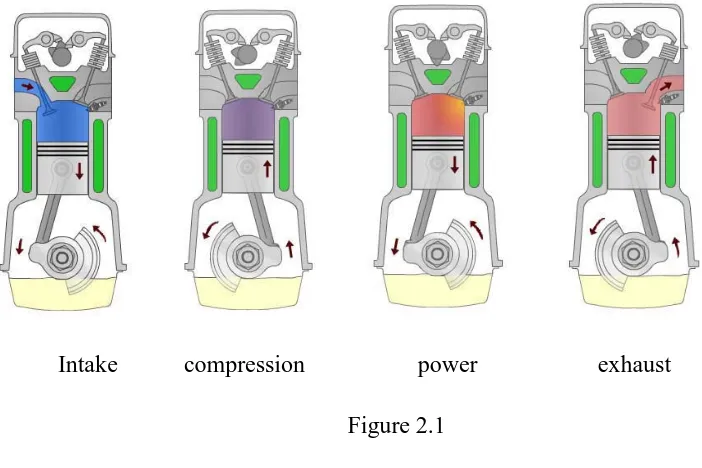
2.1The concept of the 4 stroke engine
Intake port and exhaust port are the port of the engine. The intake port will be allows the air fuel mixture into cylinder. Burned gases leave the cylinder through the exhaust port. The air is coming from the intake manifold. Four process of the 4
stroke engine is intake process, compression process, power process and exhaust process.
At the intake process, the inlet valve is opened while the exhaust valve is closed. The piston is come down from top dead centre to bottom dead centre. The mixture is sucked into the cylinder.
At the compression process, the inlet valve and exhaust are closed. The piston is come up from bottom dead centre to top dead centre. The mixture is compressed and spark ignites.
At the power stroke process, the inlet valve and exhaust valve are closed. The piston is come down from top dead centre to bottom dead centre. The mixture is burn.
At the exhaust process, the inlet valve is closed while the exhaust valve is opened. The piston is come up from bottom dead centre to top dead centre. Burnt gas is pushed out of the cylinder.
The figure 2.1 shows the concept of four stroke engine:
[image:18.595.102.453.465.699.2]
Intake compression power exhaust Figure 2.1
2.2The type of fuel injection systems
The first method for fuel injection is the direct injection into the cylinders, but unfortunately it suffers from an extraordinarily high back-pressure due to its placement, as well as other severe disadvantages. Because of the close proximity of the injectors to the pistons in the cylinder chamber, fuel must be injected progressively to allow for atomization of the fuel and mix with the air before the spark. The fuel must also be able to enter the cylinder chamber flowing against the rising back pressure. Because of the exposure of the injector tips to the combustion process, carbon build-ups easily clog the injector tips. Lastly, a complete atomization and mixing of a homogeneous air and fuel mixture are almost impossible because of the short time frame. With all of these potential problems, this method of injection is avoided for more efficient systems. Throttle body injection, also known as single-point injection or central fuel injection, has been a favourite of manufacturers because of its simplicity and low cost compared to its major competitor, the multi-point injection systems. This system relies on a single fuel injector downstream of the throttle valve, which reduces the effects of the air flow, or a dual jet fuel injector setup, upstream on each side of the butterfly valves.
However, there are several disadvantages to the single-point injection system. In a single-point injection system, the fuel has the tendency to condense fashion, partially taking away control of the system. Similarly to the carburettor, the single-point injection has difficulty distributing the fuel mixture accurately to the different cylinders. Lastly, there must be a hot spot in the throttle body to aid in the atomization of the injected fuel as well as preventing icing during cold conditions. Multi-point fuel injection is the most widely used fuel injection system employed in today's automobiles. This system works by injecting fuel into the intake manifold directly into the cylinder head ports. Implementing this direct injection to the cylinder head ports, the multi-port system avoids the previously mentioned disadvantages of the single-point system. The fuel injector is directed to spray onto the hot inlet valves, preventing condensation of the fuel in the port as well as decreasing the likeliness of the fuel mixture being drawn into an adjacent cylinder due to the effects of back pressure. The only real disadvantage of this system is the extra cost from specialized intake manifolds and extra components such as fuel rails,
which are outweighed by the better performance achieved. ( Garrett W. Balich and Conrad R. Aschenbach, 6 May 2004)
[image:20.595.134.461.187.381.2]The figure 2.2 shows the basic fuel system:
Figure 2.2
2.3The basic engine parts
The figure 2.3 shows some of the main engine parts:
Figure 2.3 i. Engine Block
The block, highlighted at right in grey, is a heavy metal casting, usually cast iron or aluminium, which holds the lower parts of the engine together and in place. The block assembly consists of the block, crankshaft, main bearings and caps, connecting rods, pistons, and other components, and is referred to as the bottom end. The block may also house the camshaft, oil pump, and other parts. The block is machined with passages for oil circulation called oil galleries (not shown) and for coolant circulation called water jackets. (2007 Melior, Inc.)
ii. Cylinders
The cylinders are round holes or bores machined into the block for the pistons to travel up and down in.
[image:21.595.134.441.137.464.2]iii. Pistons
Combustion pressure acts upon the tops of the pistons in the cylinders, forcing them downward. Usually made of aluminium, the pistons transmit the downward force to the connecting rods. The top of the piston’s travel is called Top Dead Centre (TDC) and the bottom of a piston’s travel is called Bottom Dead Centre (BDC).
(2007 Melior, Inc.)
iv. Piston Rings
Rings are installed in grooves around the pistons to form a seal between the piston and the cylinder wall. Two types of rings are used: compression rings, which prevent combustion pressure from entering the crankcase, and oil control rings, which prevent engine oil from entering the combustion chamber above the piston. Oil rings scrape excess oil from the cylinder walls for return to the crankcase. (2007
Melior, Inc.)
v. Connecting Rods
A rod connects each piston to the crankshaft. The small, upper end of the rod commonly has a bushing pressed into it. A piston pin, or wrist pin, attaches the piston to the rod through this bushing, which allows the rod to pivot as needed. The larger, lower end of the rod is attached to the crankshaft through rod bearing inserts that are stationary relative to the rod and allow the crankshaft to turn within the rod on a film of oil. (2007 Melior, Inc.)
vi. Crankshaft
The crankshaft is a strong, alloyed iron or steel shaft that converts the up-and-down motion of the pistons into a turning motion that can be transmitted to the drive train.
The crankshaft is supported by the block in several places along its length. The crankshaft rides in main bearings, which are inserts similar to the rod bearings at these supports. Where the crankshaft is connected to the rods and where it is supported by the block are called journals. The crank is finely machined and polished at these places. The crankshaft is also drilled with a network of oil passages to
deliver oil under pressure to these places from the oil galleries. Counterweights are formed onto the crankshaft to help prevent vibration. These weights are added to offset the weight of the piston and connecting rod assemblies. At the front of the crankshaft, outside the engine front cover, a heavy wheel containing a rubber vibration damper is installed. Also called a harmonic balancer, it often incorporates the crank drive belt pulley, which powers belt-driven accessories. At the rear of the crankshaft, a large flywheel is mounted. The flywheel can serve several purposes: a ring gear is mounted to its circumference to provide a means to start the engine. It also connects the engine to the transmission. Finally, on vehicles with manual transmissions, the flywheel is made very heavy to help smooth out power pulses from the engine (this is accomplished by the torque converter on vehicles equipped with automatic transmissions). (2007 Melior, Inc.)
vii. Cylinder Head
Cylinder heads are usually cast from either iron or aluminium. Most V-type, opposed, and W-type engines have two cylinder heads. Inline engines have only one cylinder head. The head bolts to the top of the block, covering and enclosing the tops of the cylinders. The head forms small pockets over the tops of the pistons called combustion chambers. The spark plugs are threaded into holes in the head and protrude into the combustion chambers (gasoline engines). Intake ports and exhaust ports are cast into the head, and small holes called valve guides are machined into it to position the valves. The valves act as gates. When open, they let air and fuel into the cylinder and exhaust gas out. When closed, they seal the pressure of compression in the combustion chamber. The valves close against machined, press-fitted inserts in the combustion chamber ports called valve seats. On overhead cam engines like the one pictured here, the head also houses the camshaft. The assembly, together with other valve train components and the intake and exhaust manifolds, is referred to as the top end. Between the head and the block, a head gasket seals the combustion chambers, and water and oil passages. (2007 Melior, Inc.)
viii. Valve Train
The valve train consists of the valves, camshaft, and other associated parts. The valves control the flow of the incoming air-fuel mixture and the outgoing exhaust
gasses. The intake valves are larger than the exhaust valves, and many engines today have two intake and two exhaust valves per cylinder to improve efficiency and performance. (2007 Melior, Inc.)
2.4Engine Mechanical Diagnosis
2.4.1 Diagnosing excessive oil consumption
Most vehicle manufacturers define “excessive oil consumption” as consuming or using a US quart or more of engine oil in 1,000 miles or less of vehicle operation. Lesser rates of oil consumption are considered normal operation in almost every case. Gaskets and seals are used in every engine to keep engine oil contained inside the engine’s lubrication system. Oil consumption almost always occurs as a result of oil leaking out of its normal location after a gasket or seal has failed. Even a relatively small internal or external oil leak can cause the loss of a quart of oil over 1,000 miles of vehicle operation. Keep in mind that gaskets and seals are designed and engineered to keep the engine oil confined to where it is supposed to be inside the engine. This includes keeping oil out of the combustion chambers and cooling system. (2007
Melior, Inc.)