II DEVELOPMENT OF MEASUREMENT SYSTEM FOR INDIRECT HAND GRIP
FORCE AND WRIST ANGLE FOR BIONIC HAND
FAZILLA BINTI MD AMIN TENG
A report submitted is partial fulfillment of the requirements for the degree of Mechatronic Engineering
Faculty of Electrical Engineering
UNIVERSITI TEKNIKAL MALAYSIA MELAKA
I “I hereby declare that I have read through this report entitle “Development of Measurement System for Indirect Hand Grip and Wrist Angle for Bionic Hand” and found that it has comply the partial fulfillment for awarding the degree of Bachelor of Mechatronic Engineering”
Signature : ……….. Supervisor’s Name : Dr Fariz bin Ali @ Ibrahim
III I declare that this report entitle “Development of Measurement System for Indirect Hand Grip and Wrist Angle for Bionic Hand” is the result of my own research except as cited in the references. The report has not been accepted for any degree and is not concurrently submitted in candidature of any other degree.
Signature : ……….……….
Name : Fazilla binti Md Amin Teng
V ACKNOWLEDGEMENT
In the name of Allah the most beneficent and the most merciful, with His bless I manage to complete my final year project 2 (PSM2) report entitled “Development of Measurement System for Indirect Hand Grip and Wrist Angle for Bionic Hand”. At the very first, I would like to express my greatest appreciation to everyone that involve in completing my report especially to my supervisor, Madam Norafizah binti Abas and Dr Fariz bin Ali @Ibrahim who gives me the full guidance and encouragement without giving up until the very end. Their willingness to give their time generously to help me has been very much appreciated.
VI ABSTRACT
VII ABSTRAK
VIII TABLE OF CONTENTS
CHAPTER TITLE PAGE
ACKNOWLEDGEMENT V
ABSTRACT VI
ABSTRAK VII
TABLE OF CONTENT VIII-X
LIST OF TABLE XI
LIST OF FIGURES XII-XIV
LIST OF APPENDICES XV
1 INTRODUCTION
1.1 Research Background 1-2
1.2 Motivation and Significant of the Research 2-3
1.3 Problem Statement 3
1.4 Objectives 4
1.5 Scope 4
1.6 Report Outline 5-6
2 LITERATURE REVIEW 2.1 Theory and Basic Principle
2.1.1 Anatomy of Human Hand 7-8
2.1.2 Electromyography (EMG) 8-10
2.2 Test Bed of this Project
IX 2.3 Previous Work done
2.3.1 Bionic hand controller and muscle selection 13-15 2.3.2 Performance test of bionic hand 15-17
2.3.3 Summary 17-19
3 METHODOLOGY
3.1 Introduction 20-22
3.2 Design and development of measurement system 22 3.2.1 Design of measurement system in Proteus 23
3.2.1.1 Stage 1: Pre-amplifier 23-26
3.2.1.2 Stage 2: Band Pass Filter 26-28
3.2.1.3 Stage 3: Full wave precision rectifier 29 3.2.1.4 Stage 4: Smoothing Circuit 30-31 3.2.1.5 Stage 5: Inverting Amplifier 31-32
3.2.1.6 Power Supply 32
3.2.1.7 By pass capacitor 33
3.2.2 Simulation on EMG Measuring Circuit 33-35 3.2.3 Developing of Designed EMG Measuring circuit 35-38 3.3 Establishment Relationship of hand grip force and wrist
angle 38
3.3.1 Muscle selection 39
3.3.2 Components used 40
3.3.3 Pre-task Procedure 41
3.3.4 Skin Preparation Procedures 42-43
3.3.5 Impedance test 43-44
3.3.6 Electrode selection 44
3.3.7 Experiment 1: Experiment setup for signal
extraction 44-45
3.3.8 Establishment relationship of hand grip force and
wrist angle 45
X 3.4.1 Performance of Bionic Hand in terms of
Repeatability 47
3.4.2 Experiment 2: Repeatability experiment. 47-48 3.4.3 Performance of Bionic hand in terms of Accuracy. 48 3.4.4 Experiment 3: Performance of Bionic hand in
terms of Accuracy 48-50
3.5 Summary 50-51
4 RESULTS AND DISCUSSION
4.1 Introduction 52
4.2 Design and development of measuring system 53-54 4.3 Establishment of the relationship between forearm EMG
signal and hand grip force 54-61
4.4 Performance of Bionic Hand in terms of Repeatability. 61-62 4.5 Performance of Bionic hand in terms of Accuracy. 63-70
5 CONCLUSION AND RECOMMENDATION 71-72
REFERENCES 73-75
APPENDIX A 76-78
APPENDIX B 79-81
APPENDIX C 82-84
XI LIST OF TABLES
TABLE TITLE PAGE
1.1 Number registered person with disabilities in Malaysia 2 2.1 Summary of Bionic Hand Controller and Muscle Selection 18
2.2 Summary of the performance test of bionic hand 19
3.1 Summary of components selection. 40
3.2 Recommendation for electrode/skin impedance range 43
4.1 EMG power varies to wrist angle for 20N grip force 55
4.2 EMG power varies to wrist angle for 60N grip force 56
4.3 EMG power varies to wrist angle for 100N grip force. 58 4.4 Performance of Bionic Hand in terms of Repeatability 61-62 4.5 Flexion angle of θ1 and θ2 for accuracy test 64
4.6 Measured average angle of all finger joints 69
4.7 Expected average angle of all finger joints 69
4.8 Percentage error for each of the finger 70
XII LIST OF FIGURES
FIGURE TITLE PAGE
1.1 Patient that suffer Thalidomide 2
2.1 Flexor Digitorum Sublimis Muscle 8
2.2 Different thickness of tissue layer produce different
amplitude EMG signal 10
2.3 Mechanical design of bionic hand by Mohamad Fakri 11 2.4 Stroke Subject completing foam test by N.S.L. Ho 15 2.5 Test of Prosthetic hand in grasping a cylindrical,
elliptical form, pet bottle, holding a pen and CD case by Hirosgi Yokoi
16
2.6 Prosthetic hand motion 17
3.1 Flowchart of Methodology 21
3.2 Schematic of the differential amplifier configuration 23
3.3 Pin configuration of AD620 24
3.4 Preamplifier circuit with DRL concept. 26
3.5 Online Calculator Sallen Key High Pass Filter 27
3.6 Online Calculator Sallen Key Low Pass Filter 28
3.7 Sallen key High pass and low pass filter 28
3.8 Full Wave Precision Rectifier 29
3.9 Smoothing circuit 31
3.10 Online calculator of low pass filter for smoothing circuit 31
3.11 Inverting amplifier of the circuit 32
3.12 Measurement circuit for simulation in Proteus Software 34
3.13 Graph obtained from the simulation 35
3.14 Measuring Circuit on the breadboard. 36
XIII Proteus ARES software
3.16 Back side of measuring circuit PCB design using ARES
Proteus 37
3.17 Front side of measuring circuit on the real PCB 37 3.18 Back side of measuring circuit on the real PCB. 38 3.19 Overall system in achieving the second objective 38
3.20 Hand palm on the medial epicondyle 39
3.21 Electrodes are placed on the hand skin below the ring
finger 39
3.22 Impedance test using Multi-meter 42
3.23 Wrist is moved to 90 degree based on the printed
protector 44
3.24 Wrist is moved to 60˚ and 120˚ based on the printed
protector 45
3.25 Overall system in achieving the third objective 46
3.26 Experimental set up for Repeatability test 47
3.27 Experiment set up for Accuracy test. 49
3.28 Pinkie finger of the bionic hand bends 49
3.29 Others finger of bionic hand bend. 50
3.30 Frame of pinky finger measured 50
4.1 Design measuring system circuit in PCB 53
4.2 EMG signal taken from oscilloscope 54
4.3 Average peak-to-peak EMG voltage (mV) versus wrist
angle (degree) at 20N grip force 56
4.4 Average peak-to-peak EMG voltage (mV) versus wrist angle
(degree) at 60N grip force 57
4.5 Average peak-to-peak EMG voltage (mV) versus wrist
angle (degree) at 100N grip force 58
4.6 Average value peak-to-peak enveloped EMG voltage varies
to hand grip force and wrist angle 59
XIV 4.8 Graph of Angle of Thumb Joint versus No of Test 65
4.9 Graph of Angle of Point Joint versus No of Test 66 4.10 Graph of Angle of Middle Joint versus No of Test 67 4.11 Graph of Angle of ring Joint versus No of Test 67 4.12 Graph of Angle of pinkie Joint versus No of Test 68
A.1 Average value peak-to-peak enveloped EMG voltage varies
to hand grip force and wrist angle (second subject) 78
A.2 Average value peak-to-peak enveloped EMG voltage
XV LIST OF APPENDICES
APPENDICES TITLE PAGES
A Average value peak to peak EMG voltage for second subject
76-78
B Average value peak to peak EMG voltage for third subject
79-81
C Programming of Arduino Uno 82-84
1 CHAPTER 1
INTRODUCTION
1.1 Research background
2 Figure 1.1: Patient that suffer Thalidomide
1.2 Motivation and significant of the research
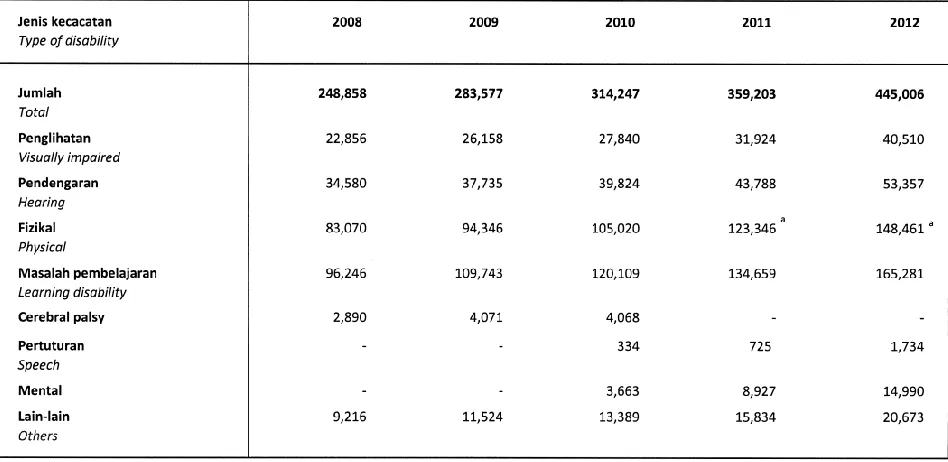
Referring to the Perangkaan Sosial Negeri/Daerah 2013, the Table 1.1 shows the number of registered person under the department of social welfare with disabilities in Malaysia from year 2008 to 2012. In this table it shows that the number of disability people is increasing year by year.
[image:17.612.90.564.450.681.2]3 For physical disabilities, in year 2008 it shows that the number of patient registered is 83070, followed by 94346 in year 2009, 105020 in 2010, 123346 in 2011 and finally 148461 in year 2012. This physical disabilities includes patient that had lost their hands, hand paralyzed and so on. For patient that facing this problem of maimed hand, their daily activities become limited and difficult for them to adapt to the daily environment. This is because they will have a difficulty to perform basic movements such as holding an object or grasping an object. To improve their daily life activities, a bionic hand by using designed measuring circuit is proposed.
1.3 Problem statement
4 1.4 Objectives
The objectives of this final year project (FYP) are to:
1. Design and develop a measurement system to extract forearm EMG signal and interface the signal with designed bionic hand.
2. Establish the relationship between forearm EMG signal and hand grip force and use this relationship to predict the hand grip force exerted and joint wrist angles when forearm EMG signals are used as input.
3. Analyze the performance of the bionic hand in term of repeatability and accuracy by using the designed measurement system.
1.5 Scope
The scopes that cover in this final year project are:
1. The EMG signal that extracted from the electrodes that attached to hand is used as the input of the system.
2. The bipolar electrodes are used in order to extract the EMG signal from Flexor Digitorum Superficialis (FDS) muscle.
3. Mohamad Fakri bionic hand designed will be used as the test bed of this project. 4. The angle considered to establish the relationship between the forearm EMG signal are
5 1.6 Report outline
This report consists of 5 chapters which are Introduction, Literature Review, Methodology, Preliminary Results and conclusion and recommendation. In first chapter which is Introduction, it basically talks about the objectives of project. It covers the research background of the bionic hand, motivation and significant of the research, problem statement, scope and report outline.
In chapter 2, it talks about literature review which covers the theory and basic principle, test bed of the project and also reviews of the previous related works. In this theory and basic principle, its covers the basic theory of the anatomy of hand and electromyography. The test bed of this project is developed by Mohamad Fakri which it covers the mechanical design and component selection of the bionic hand. In this chapter also, several reviews of the previous related works which taken from the journals are compared to choose the best controller and muscles to used. From the review, summary is made.
6 In chapter 4, it covers the results obtained from each experiment that had been done. Each of the experiment is done in order to achieve every objective in this project. Analysis and discussion is made based on the results that obtained.
7 CHAPTER 2
LITERATURE REVIEW
2.1 Theory and basic principle
In this section, theory and basic principle that are related to the development of bionic hand. It covers the anatomy of human hand which it talks about the muscle in hands. This section also covers the introduction of electromyography signal, which talks about the benefits of EMG signal and the factor influence it. In this section also, it covers on the information for test bed of the bionic hand that is developed by Mohd Fakri. Finally, it covers on the previous work done in terms of bionic hand controller and muscle selection and the performance test of bionic hand.
2.1.1 Anatomy of human hand
8 profundus (FDP) and many more. However, there are two main contribution of muscle in gripping hand which are Flexsor digitorum sublimis (FDS) muscle and Flexsor digitorum profundus (FDP) muscle.
[image:23.612.287.358.336.472.2]Referring to Innerbody et al. Flexor digitorum superficialis (FDS) is a large muscle that located along the bottom of the forearm from all the bones at the elbow to the four fingers as shown in Figure 2.1. It serves to flex or curl of the fingers. This muscle is divided into two distinct heads which are the radial and humeroulnar. [3] The median nerve and ulnar artery travel through these two heads. A flexor muscle is the one that decreases the angle between the two bones such as bending the arm at the elbow.
Figure 2.1.: Flexor digitorum sublimis muscle [3]
-2.1.2 Electromyography (EMG)
9 Meanwhile, the third electrode is placed in a natural area where its output is used to cancel the noise that can interfere with the signals from the other two electrodes.
Electromyography (EMG) signal is a small electrical current that generated when there is a contraction of a muscle. Since the electromyography signal levels are too low to be captured directly by the computer, the signal is required to amplify to a TTL level that ranged between -5volts to +5volts. By amplifying the EMG signal, the computer can store and read the data in the file format. However, there are many critical factors that must be considered such as noise and artifact problems could distort the signal. Other than that, Additional DC current could also add offset to the EMG signal. Finally, the size of the device should be taken into consideration as the equipment will be attached to the forearm during the EMG recording.
Referring to Aditya Veer Singh Rana et al. the measurement of the electrical activity of the muscle in the hand is the results of a signal that generates in the brain which is transmitted through the nervous system to the motor neuron attached to the muscle fibers. The motor neurons resulting in a depolarization or repolarization wave throughout the muscle fiber. This wave creates action potential in the muscle fibers resulting in the movement of the electrical charge that produces an electrical signal in the muscle. This electrical signal can be picked up by the well-placed electrodes that attached on the surface of the skin. The received signal is EMG signal. The amplitude of EMG signal is depends on the amount of force delivered by the biceps. The stronger the contraction of the muscle the larger the amplitude of the EMG signal. [5]
![Figure 2.1.: Flexor digitorum sublimis muscle [3]](https://thumb-us.123doks.com/thumbv2/123dok_us/137047.14191/23.612.287.358.336.472/figure-flexor-digitorum-sublimis-muscle.webp)