Improved Data Compression for Serial Interconnected Network on Chip
through Unused Significant Bit Removal
Simon Ogg, Bashir Al-Hashimi
∗
Southampton University, Southampton, UK
[email protected], [email protected]
Abstract
Serial links in network on chip provide advantages in terms of reduced wiring area, reduced switch complexity and power. However, serial links offer lower bandwidth in comparison to parallel schemes. Poor bandwidth increases the risk of congestion and potential loss of packetised data. This paper proposes a simple yet effective real-time compression technique that reduces the amount of bits sent over serial links. The proposed technique reduces the number of bits and the number of transitions when compared to the original uncompressed data. A case study showing the results of compression on two MPEG1 coded picture data shows average bit reductions of approximately 17% to 47% and average transition reductions of approximately 15% to 24% over a serial link.
1.
INTRODUCTION
∗Network on Chip (NoC) is an emerging interconnection design methodology which is seen as a promising solution to provide scalable, energy efficient and reliable communication for System on Chip [1-3]. In NoC, data is routed from one core to another through switches, the links between the switches could be parallel or serial, each of which has advantages and disadvantages. A serial link, for example, has lower wiring density and reduced crosstalk, but reduced bandwidth when compared to parallel. Morgenshtein [4] analysed serial and parallel links in NoCs and concluded that on-chip interconnects could benefit from serial links. The analysis showed that improvements could be as much as x5.5 for area and x17 for power in the communication link due to the low number of wires and repeaters in serial links. Kimura [5] and Lee [6] have both implemented serial links in practice and shown they are viable for use in high speed, low power on chip network communication.
Whilst there exists publications that deal with reducing power of parallel links [7,8], there is little reported work on reducing power in serial links apart from Lee [9] who has recently proposed a coding technique, SILENT, for serial transmission on NoC that reduces power effectively. This is achieved by XORing data with the previous data so that only
∗ The authors would like to acknowledge the Engineering and
Physical Sciences Research Council (EPSRC) for funding under grant no. EP/C512804.
the differences between successive words cause a transition on the serial link. With their example application the number of transitions is reduced by 40%. However, it is important to note that in their scheme the original amount of data is not reduced.
The previous work [4,6,9] has demonstrated the benefits in terms of area and power when employing serial links to connect the switches of a NoC. The motivation of this paper is to investigate and develop a technique that will allow data transfers to overcome bandwidth limitations associated with serial links. This is achieved through our proposed simple compression technique that exploits the bit level similarities of successive data words. The rest of this paper is organised as follows; Section 2 describes how the basic compression is performed, taking into consideration fixed and dynamic blocks lengths of data, and finally an algorithm which can dynamically alter the block sizes to suit the current data is proposed. Section 3 gives experimental results of dynamic and fixed block sizes on two example intra-coded picture data from MPEG1 video-streams. Section 4 presents the conclusions.
2.
PROPOSED TECHNIQUE
As the bandwidth in the NoC is limited there exists a motivation for compressing data in serial linked NoC to reduce the overall bits being transmitted. The reduction in bits transmitted by Unused Significant Bit Removal (USBR) would directly give spare bandwidth capacity within the network communication structure. The proposed technique is aimed at data streams where the most significant bits are less likely to change than least significant bits, such as situations where the variance of the data is sometimes small for a certain number of words. If the variance of the data is small then it is likely that the significant bits will change less and USBR can be used to compress the data. Consider Figure 1, the binary data given has the most significant bit that changes in each word underlined (Figure. 1A).
The extra bits added can be considered as additional overhead.
D0 00111100 D1 00111001 D2 00011101 D3 00000001 D4 00001100 D5 00001011 D6 00011111 D7 00010100
Most Significant Bit that Changes Bits do not change
[image:2.612.77.294.96.187.2](A) (B) (C)
Figure 1 Example 8x8bit block of data
As an example, assume an overhead of 8 bits is used, 3 of which signify what bits change (23 can signify that 1 to 8 bits
change) and 5 of which signify the block length (25 = 32, in
length if necessary). Referring to the example in Figure 2 it can be seen that 14 bits are removed from the block (Figure. 2A). The overhead of 8 bits is then added to the start of the block (Figure. 2B). The overhead would show that the 6 least significant bits change in the block and the block length is 8. Note that the 1st data word stays complete as a starting
reference point for the subsequent data words which have been reduced to 6 bits each. The number of bits is reduced from 64 to 58 in this example.
Up to now the block length has been considered as a fixed. The block length in the example is 8. It is difficult to say what the optimum block length is without knowledge of the data to be compressed. A general guideline is to make the fixed block size similar to any inherent groups of consecutive data that show minimal data variance. For example, in section 3 a fixed block size of 64 is used for MPEG picture data. This is because picture data is often processed in units that consist of six groups of 64 words, the less complex the picture, the less variance there generally is within each group. It is important not to make the block size too large as this would impact the size of any buffer which has to hold the data. Increasing the buffer size will increase the area cost of implementation. Conversely, making the fixed block size too small will lead to compression inefficiencies where the any potential gains from removing redundant bits would be impacted by an increased amount overhead bits being used for the increase in the number of blocks resulting from higher fragmentation of the data.
An alternative to fixed block length is to dynamically alter the length on a block by block basis. This is useful for situations where there is no inherent grouping of data that can be seen. If the block length is fixed the implementation of performing the proposed compression technique becomes simple since the block length stays constant. Using an algorithm to allow dynamic block sizing based on information about the data can be done but this will impact the area of the transmitter and receiver since the circuitry would be more complex. Dynamic block sizing will now be discussed in more detail.
It is common to buffer data within the network switch interface to store data before being packetised to make sure data is transferred efficiently. For dynamic block sizing a queue such as a FIFO could be used to provide information about how to compress the buffered data. The information in the queue would consist of some overhead information which
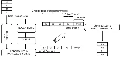
signifies the block length and the number of bits which change or stay the same. Figure 3 shows a simplified block diagram of data flow through the transmitter and receiver of the compression scheme. A further, more detailed, diagram is shown in Figure 6.
64 bits 58 bits
LEN
G
TH
OVE
R
H
E
AD
LSBSCHANGE
MSBSSAME
BITWIDTH No. Bits Change Block Length
00111100 00111001 00011101 00000001 00001100 00001011 00011111 00010100
01100111 00111100 111001 011101 000001 001100 001011 011111 010100
01100111 00111100 111001 011101 ..etc
No. Bits Change = 6 Block Length = 8
1st word
2nd word
Overhead
[image:2.612.320.535.133.284.2](A) (B) (C)
Figure 2 Example of compression
A simple algorithm is proposed that effectively uses pointers which point to the start of 3 successive minimum length blocks in the data. Using 3 pointers allows the algorithm to make two decisions, to continue to merge blocks together or to store information about the current merged block and start a new block. To get the minimum length for a block it is necessary to know when compression will be worthwhile. Referring to the labelled example in Figure 2C the following equation must be satisfied in order to achieve compression.
(LENGTH×LSBSCH)+MSBSSM +OVHD<LENGTH×BITWIDTH
LENGTH = length of the block,
LSBSCH = number of Least Sig. Bits that change MSBSSM = number of Most Sig. Bits that stay the same OVHD = overhead in bits
BITWIDTH = bit width of the data words
DA
TA
BU
F
F
ER
QUEUE
Serial Data Out Core Payload Data
BLOCK SIZING
CONTROLLER & PARALLEL to SERIAL
D0 D1 D2 D3
OVHD D0 D1 D2 D3
CONTROLLER & SERIAL to PARALLEL Serial Data In
OVHD D0 D1 D2 D3
D0 D1 D2 D3
Overhead Entire 1st word
Changing bits of subsequent words
Figure 3 Overview of Data Flow between serial transmitter and receiver
[image:2.612.325.530.489.587.2]// Initialize the pointers by getting the first three minimum blocks GetNextBlock(p0), GetNextBlock(p1), GetNextBlock(p2)
while (not at end of data) // Main loop {
// bias = 4
// Net savings merging p0 + p1
// = - potential savings lost + overhead + bias
// Net savings merging p1 + p2 // = - potential savings lost + overhead
// Evaluate the merging options
if merging block 0 and 1 gives best savings
p0 = Merge(p0,p1)
p1 = p2
GetNextBlock(p2)
else if merging block 1 and 2 gives best savings store p0 info in queue
p0 = Merge(p1,p2)
GetNextBlock(p1) GetNextBlock(p2) } end while
GetNextBlock(p) // Gets minimum sized block that will compress
[image:3.612.75.294.75.237.2]Merge(p,p) // Merges the two blocks together
Figure 4 Algorithm for dynamic block sizing
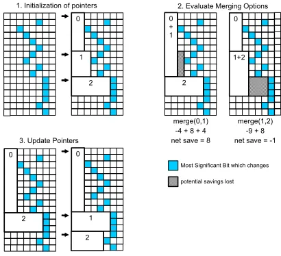
An example initialization, evaluation and update cycle is shown in Figure 5. First, three minimum length blocks are found. These three minimum length blocks are then evaluated for two possible merging options, merging block 0 and block 1 or merging block 1 and block 2. In the example shown in Figure 5, merging block 0 and block 1 results in the loss of 4 bits. However, the merge operation would also remove one set of overhead bits, in this case 8 bits. Furthermore a bias value is used when calculating the potential savings when merging block 0 and block 1. This is done to encourage the algorithm not to fragment the data into too many blocks. The resulting net savings for merging block 0 and block 1 will therefore be -4+8+4 giving a total of +8. Merging block 1 and block 2 in Figure 5 shows that 9 bits are lost and 8 bits are saved through removing overhead bits. This gives a total net saving of -1. Merging block 0 and 1 gives the best overall net bit savings. The merge is performed and the pointers are updated.
0 + 1
2
0
1+2
merge(0,1) merge(1,2) net save = 8 net save = -1
potential savings lost
-4 + 8 + 4 -9 + 8 0
1
2
Most Significant Bit which changes
0
2
0
1 2
1. Initialization of pointers 2. Evaluate Merging Options
3. Update Pointers
Figure 5 Initialization, evaluation and update cycle
This whole process is continuously performed again. Anytime block 1 and block 2 is merged the information about block 0, the length and number of bits that change, is stored in a queue to allow the already buffered data to be
compressed. The queue will contain the length and changing bits information that allows the data in the buffer to be compressed. Figure 6 shows a possible implementation of the compression technique in hardware. The packet header generation is ignored in this diagram and just the payload data is considered for clarity. The general structure outlined shows a transmitter consisting of a buffer, block sizing unit, queue, controller and parallel to serial converter. The receiver consists of a serial to parallel converter where each bit can be addressed and a controller. For the transmitter, the data is written into a buffer from the core as normal but at the same time the block sizing unit is collecting information on the data and working out ways to try and compress the data. As the block sizing unit finds the best way to split the data into blocks the information is written into a queue. The controller then takes information from the queue regarding the length and number of bits that change and uses these to drive the parallel to serial converter correctly. The parallel to serial converter shifts out the overhead information from the queue, the entire first data word and then only the bits that change within the block for each word.
BLOCK SIZING
Serial Data Out
Da
ta
Pointer Management D0
D1 D2 D3
OVHD D0 D1 D2 D3
Serial Data In
D0 D1 D2 D3
Overhead Entire 1st word
Changing bits of subsequent words
FI
FO
Wr
ite
_En
p0 p1 p2
ƒ
ƒ
Merge CTRL
p0 (bits, length)
FI
FO
DATA BU
FFER
Write_En
QUEUE
(bits, length)
Da
ta
TX SHIFT CTRL
PARALLEL TO SERIAL Load, Shift Data_OVHD_Sel
RX SHIFT CTRL
Bit
_Se
l
Lo
ad
_P
ar
a
Da
ta
OVHD_REG
Bit
s
Le
ng
th
(bits, length)
Da
ta
Wr
ite
_En
SERIAL TO PARALLEL DATA / OVHD SEL
DATA FROM SOURCE CORE
DATA TO DESTINATION CORE
T
R
AN
SMI
T
RE
CE
[image:3.612.331.538.294.444.2]IVE
Figure 6 Implementation for dynamic block sizing
[image:3.612.79.284.457.644.2]3.
EXPERIMENTAL RESULTS
[image:4.612.327.529.191.320.2]In order to confirm the effectiveness of USBR in compressing data over a serial link we applied the technique to two MPEG intra-coded pictures shown in Figure7, one of which is showing a bike jumping from a wall and the other showing an American football game. Each example picture is used with a 15 bit fixed point and 10 bit fixed point representation of the YUV data. The resulting bit and transition percentage reduction for each picture is summed and then averaged. The amount of overhead was set at 16 bits per block and the bit-width set at 16.
Figure 7 Pictures bike.m1v [10] & football.m1v
Figure 8 shows the average reduction of the bits being transmitted for the two example pictures for 10 and 15 bit precision with a block bit-width of 16. The uncompressed labelled bar shows the original amount of data normalised to 100%. The three further bars show the resulting amount of data from SILENT, fixed and dynamic techniques. As it can be seen fixed and variable block sizes using the proposed USBR has been reduced from 100% to 53.3% for fixed and 56.9% for dynamic using 10 bit precision. The bit reduction for 15 bit precision is less than 10 bit precision due to the higher precision using more significant bits to represent the data. For fixed block sizing the length of each block was 64, for dynamic the block lengths were determined by the algorithm in Figure 4, which resulted in a minimum data block length of 3 and a maximum 455 for the 15 bit precision football example. For the bike example a minimum data block length of 3 and maximum of 313 was observed. If the maximum length of the data blocks are too big for the transmitter buffer to handle the block lengths can be capped to a more suitable maximum length.
Bit Reductions
100.0%
100.0% 100.0%
100.0% 53.3%
82.3% 56.9%
83.3% 10 bit
15 bit
P
ict
u
re D
a
ta
P
re
c
is
ion
UnCompressed
SILENT [9]
Fixed (proposed)
[image:4.612.75.292.206.281.2]Dynamic (proposed)
Figure 8 Average Reduction in Bits Transmitted
To examine how the proposed technique reduces the number of transitions and therefore the power, Figure 9 shows the average reduction of transitions for the two example pictures. It can be seen that the transitions have been reduced from 100% (uncompressed) to 76% for fixed and to
81.2% for dynamic using 10 bit precision picture data. Again, 15 bit precision picture data shows reduction in transitions. To provide a comparison to previous work Figure 9 shows the transition reduction using SILENT. The transition reduction using SILENT is better than our proposed technique reducing the transitions from 100% to 52.7% but this is achieved without any bit reduction (see Figure 8). To achieve both bit and transition reduction a combination of the USBR and SILENT can be used as shown in Figure 9. This shows transition reductions from 100% to 51% for fixed and 54.5% for dynamic using 10 bit precision.
Transition Reductions
100.0%
100.0% 52.7%
64.3% 76.0%
83.2% 51.0%
63.1% 81.2%
84.2% 54.5%
63.9% 10 bit
15 bit
P
ict
u
re D
a
ta
P
reci
si
o
n
UnCompressed
SILENT [9]
Fixed(proposed)
Fixed + SILENT
Dynamic(proposed)
Dynamic + SILENT
Figure 9 Average Reduction in Transitions
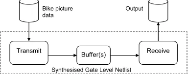
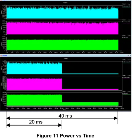
To give an idea of the cost of the proposed compression in terms of power and area, the transmitter and receiver for a fixed block size of 64 was coded in VHDL. To show how power could be saved within a NoC switch a simple FIFO type buffer was coded and used as a connection between the transmitter and receiver, Figure 10, as much of the power in a switch is used by the buffers [11,12]. The transmitter and receiver was synthesised with Synplify-ASIC using ST 0.12µm CORE9GPLL library. The synthesised design was then used in conjunction with the picture data from the bike example of Figure 7 and run through Synopsys Primepower to provide gate level power estimations for the design. The simulation time for the runs was the same for both implementations to allow a comparison of the average power. The results of the power simulation are shown in Figure 11. The top plot shows, going from top to bottom, power in the transmitter, receiver and buffer for the standard serial link. The bottom plot shows the same for USBR fixed block compression. It is noted that time to complete the transfer in the standard implementation is ~40 ms and time to complete for the fixed compression scheme is ~20 ms. This decrease in time corresponds to the approximate halving of bits for the fixed compression as shown in Figure 8, and means the overall time to transfer the data has been halved. Furthermore, the halving of the transfer time means that the activity in the buffer is halved and therefore the congestion should be lower within a NoC environment.
Transmit Buffer(s) Receive
Synthesised Gate Level Netlist Bike picture
[image:4.612.83.283.518.643.2]data Output
[image:4.612.333.525.616.692.2]As shown in Table 1, for the standard uncompressed implementation the area of the hardware is 91836 µm2. For
USBR using fixed block sizing the area is 101196 µm2
effectively an increase of 10%. Table 2 shows the power for the two implementations is very similar when the data goes through a single switch, 0.3949 mW for the uncompressed and 0.4007 mW for USBR using a fixed block size, at first there seems to be no gain in using the compression since the power increase in the transmitter section is slightly more than the power saved in the buffer. However, this power is for a single buffer only. If the data has to go through more than one switch then the additional power saving of each additional buffer within each switch exceeds the power increase in the transmitter due to compression. For example, in a NoC system if the data from the transmitting core has to pass through at least 3 switches to arrive at the receiving core then the power is reduced from 0.7031 mW down to 0.6332 mW, a power saving of around 10%. If the data has to pass through more buffers then further power is saved at a rate of 0.038 mW per buffer.
20 ms
[image:5.612.88.425.287.701.2]40 ms
Figure 11 Power vs Time
Table 1 - Area (µm2) of synthesised implementations
Transmitter Receiver Buffer Total
Standard 86830 1404 3602 91836
Fixed 93717 3862 3616 101195
Table 2 Average Power (mW) for bike picture data
1 Buffer Transmitter Receiver Buffer Total
Standard 0.1813 0.0595 0.1541 0.3949
(USBR)Fixed 0.2208 0.0635 0.1164 0.4007
2 Buffers
Standard 0.1813 0.0595 0.3082 0.5490
(USBR)Fixed 0.2208 0.0635 0.2328 0.5168
3 Buffers
Standard 0.1813 0.0595 0.4623 0.7031
(USBR)Fixed 0.2208 0.0635 0.3492 0.6332
4.
CONCLUSION
Recent research is indicating that NoC with serial interconnect provides benefits from power and area point of view. This paper has presented an effective compression technique that can be employed with such NoC, improving the bandwidth bottleneck issue. Fixed and dynamic block sizing has been considered. General guidelines for determining a suitable fixed block length and an algorithm for dynamic block sizing has been shown. The technique, USBR, exploits the fact that unused significant bits do not need to be transmitted. A possible implementation of the proposed compression technique has been outlined and the area overhead costs and potential power and bandwidth savings within a NoC environment have been presented. At present, the authors are continuing to investigate practical implementations using the proposed technique for NoC.
REFERENCES
[1] L. Benini and D. Bertozzi, "Network-on-chip architectures and design methods," IEE Proceedings-Computers and Digital Techniques, vol. 152, no. 2, pp. 261-272, Mar.2005.
[2] W. J. Dally and B. Towles, "Route packets, not wires: on-chip interconnection networks," DAC 2001, pp. 684-689. [3] S. Kumar, A. Jantsch, "A network on chip architecture
and design methodology," ISVLSI 2002 Pittsburgh, PA, USA: IEEE Comput. Soc, 2002, pp. 117-124.
[4] A. Morgenshtein, I. Cidon, "Comparative analysis of serial vs parallel links in NoC," 2004 International Symposium on SoC, 2004, pp. 185-188.
[5] S. Kimura, T. Hayakawa, "An on-chip high speed serial communication method based on independent ring oscillators," ISSCC. 2003, pp. 385-390.
[6] K. Lee, S. J. Lee, "A 51mW 1.6GHz on-chip network for low-power heterogeneous SoC platform," ISSCC 2003, pp. 152-153.
[7] Z. Khan, A. T. Erdogan, "Dual low-power and crosstalk immune encoding scheme for on-chip data buses," Electronics Letters, vol. 39, no. 20, pp. 1436-1437, 2003. [8] M. R. Stan and W. P. Burleson, "Low-power encodings
for global communication in CMOS VLSI," IEEE Trans. on VLSI Systems, vol. 5, no. 4, pp. 444-455, 1997.
[9] K. Lee, S. J. Lee, "SILENT: Serialized low energy transmission coding for on-chip interconnection networks," ICCAD 2004, pp. 448-451.
[10] vlsi.technion.ac.il/projects/2002s26/movies/bike.m1v
[11] N. Banerjee, P. Vellanki, "A power and performance model for network-on-chip architectures," DATE 2004, pp. 1250-1255.
[image:5.612.77.293.292.519.2]