IEEE 26-BUS
RAZIYAH MAZNAH BINTI ABDUL MUNAF
A report submitted in partial fulfilment of the requirements for the degree of Bachelor of Electrical Engineering (Industrial Power)
Faculty of Electrical Engineering
UNIVERSITI TEKNIKAL MALAYSIA MELAKA
“I hereby declare that I have read through this report entitle “Reactive Power Planning using Evolutionary Programming for IEEE 26-bus” and found that it has comply the partial fulfillment for awarding the degree of Bachelor of Electrical Engineering (Industrial Power)”
Signature : ...
Supervisor’s Name : Dr. Elia Erwani Binti Hassan
DECLARATION
I declare that this report entitle “Reactive Power Planning using Evolutionary Programming for IEEE 26-bus” is the result of my own research except as cited in the references. The report has not been accepted for any degree and is not concurrently submitted in candidature of any other degree.
Signature : ...
Name : Raziyah Maznah Binti Abdul Munaf
First and foremost, I would like to express my gratitude to Allah for endowing me with health, patience, and knowledge to complete this Final Year Project (FYP).
A word of appreciation is due to Dr Elia Erwani binti Hassan, my research supervisor in Electrical Engineering Faculty, who has provided me with a lot of suggestions and recommendations during this FYP.
Thanks to the Universiti Teknikal Malaysia Melaka (UTeM) for providing me crystal clear information on FYP 1 and FYP 2 processes from the beginning until the report submission.
ABSTRACT
ABSTRAK
TABLE OF CONTENTS
CHAPTER TITLE PAGE
ABSTRACT ii
TABLE OF CONTENT iv
LIST OF FIGURES vii
LIST OF TABLE viii
LIST OF ABBREVIATION ix
1 INTRODUCTION 1
1.1 Motivation 1
1.2 Problem Statement 2
1.3 Objectives 3
1.4 Scope 4
2 LITERATURE REVIEW 5
2.0 Introduction 5
2.1 Reactive Power Planning 5
2.1.1 Load Margin 6
2.2 Conventional Method 10
2.3 Heuristic Method 10
2.4 Hybrid Method 11
3 METHODOLOGY 13
3.0 Introduction 13
3.1 Objective Function 13
3.1.1 Maximizing Load Margin 14
3.2 The Important Control Variables 17
3.2.1 Generator Constraints 18
3.2.2 Load Voltage Constraints 18
3.2.3 Reactive Power Generation Constraints of Capacitor Banks
18
3.2.4 Transformer Tap Setting Constraints 18
3.3 Overview on Optimization Techniques 19
3.3.2 Development of EP Algorithm for Maximum Loading Point as objective function
21
3.4 Single Line Diagram 25
3.5 Overall Research Methodology 26
3.5.1 Flowchart 26
3.5.2 Milestone 28
3.5.3 Gantt Chart 28
4 RESULTS AND DISCUSSION 29
4.0 Introduction 29
4.1 Results for Reactive Power Planning 29
4.2 Result for Maximum Loading Point as an Objective Function and observation on Total Losses
33
4.2.1 Result for Case 1 33
4.2.2 Result for Case 2 36
4.3 Summary 39
4.3.1 Summary for Case 1 39
4.3.2 Summary for Case 2 40
5 CONCLUSION AND RECOMMENDATION 41
5.1 Conclusion 41
5.2 Recommendation 42
REFERNCES 43
LIST OF FIGURES
FIGURE TITLE PAGE 2.1 Load margin assessment, load vs. voltage 7
2.2 Comparison between pre and post RPP implementation. 8
2.3 PV Curve for Base Case and Contingency 9
3.1 Load margin acceptable range load vs. voltage 15 3.2 The flow chart for MLP as objective function 16 3.3 General graph for comparison between pre and post RPP
implementation
17
3.4 Flowchart of EP implementation to maximize MLP for Case 1 and Case 2
24
3.5 Single Line diagram of IEEE 26 Bus. 25
3.6 Shows the Flowchart of Research Methodology 27 4.1 Figure 4.1: Graph to illustrate the Point A (before implementation
of RPP) and Point B (after the implementation of RPP).
LIST OF TABLE
TABLE TITLE PAGE 4.1 P load increment before the implementation of RPP (Point A) 31
4.2 Q load increment before the implementation of RPP (Point A) 32 4.3 Q load increment during the implementation of RPP (Point A’ and
B) on Case 1
34
4.4 P load increment during the implementation of RPP (Point A’ and B) on Case 1
35
4.5 Q load increment during the implementation of RPP (Point A’ and B) on Case 2.
37
4.6 P load increment during the implementation of RPP (Point A’ and B) on Case 2.
38
4.7 Comparison between P load increment and Q load increment in term of MLP and losses on Case 1
39
4.8 Comparison between P load increment and Q load increment in term of MLP and losses on Case 2
40
3.1 Gantt chart of Research Methodology 47
LIST OF ABBREVIATIONS
AC - Alternating Current
BFO - Bacterial Foraging Optimization CPF - Continuation Power Flow DE - Differential Evaluation EAs - Evolutionary Algorithms EP - Evolutionary Programming ES - Evolutionary Strategies FACTS - Flexible AC Transmission System GA - Genetic Algorithm
GP - Genetic Programming
IEEE - Institute of Electrical and Electronics Engineers IP - Interior Point
LP - Linear Programming
MCGA - Mixed Coding of Genetic Algorithm MINLP - Mixed Integer Nonlinear Programming MLP - Maximum Loading Point
NLP - Nonlinear Programming
PoC - Point of Collapse
PSO - Particle Swarm Optimization
Q - Reactive Power
Qgs - Reactive Power Dispatch
Qinj - Compensating Capacitor Placement RGA - Real Coded Genetic Algorithm RPP - Reactive Power Planning SA - Simulated Annealing SM - Stability Margin
TS - Tabu Search
CHAPTER 1
INTRODUCTION
1.1 Motivation
Most distribution system deals with complicated load behavior as involves with numerous types of end consumers. Reactive power is an essential tool to establish and maintain an AC fluctuating magnetic flux. In almost every section of the system (generation, transmission, distribution and the loads) reactive power is either generated or consumed. The reactive power in the circuit is contributed by the inductive or capacitive reactance. Reactive power is important to control voltage level and subsequently prevent electrical equipment from damage [26] [27] [28]. Reactive power shortage can cause blackout or breakdown event in a system due to the generator and transmission line failure [9].
Reactive Power Planning (RPP) is a nonlinear multi-constraint for large scale uncertainties. There has been huge effect on RPP issue for the security and economy power system [1] [12]. For that reason, researchers in [13] claimed that RPP require the minimization of two objective functions simultaneously. The optimization of RPP problem is completed with continuous and discrete control variable such as generator bus voltages, setting of on-load tap changer of transformers and reactive power output of the compensating devices placed on different bus bars [7].
Nonlinear Programming (NLP), and Mixed Integer Nonlinear Programming (MINLP) [21]. The Heuristic method is used to overcome Conventional method drawbacks by solving potential for large scale system through their less searching time process [5]. This method comprises of Simulated Annealing (SA), Evolutionary Algorithms (EAs), Differential Evaluation (DE) and Tabu Search (TS) [21] [4]. EA is a process of natural selection and genetics which are used as search algorithms. EA, such as Evolutionary Programming (EP), Real Coded Genetic Algorithm (RGA), Evolutionary Strategies (ES), and Genetic Programming (GP) have been widely used as search and optimization tools in RPP to solve local minimum problems and uncertainties [1].
Several types of EA methods are used to solve the RPP problems over the world since 1960 [9]. The studies involved with control variables such as transformer tap setting T, generator bus voltages Vg and Volt-Ampere Reactive (VAR) source installments Qc [1]. In order to obtain the best solution for RPP objective function identified as the maximum loadability with minimum losses observation during the implementation. The IEEE 26 bus system will be tested in this RPP study utilizing by EP method during any possibility on load increment in the power network.
1.2 Problem Statement
the generation, transmission and reactive power resources. Thus the daily and seasonal load variations reactive resource consumption also changes continually. At that point, RPP is a nonlinear optimization problem for a bulky power system with a lot of uncertainties which must also considered all the constraint condition and the optimization of some control variables such as, transformer tap setting T, generator bus voltages Vg and Volt-Ampere Reactive (VAR) source placement Qc [1]. In addition, an increment of load demands will reason to insufficient voltage in the system which may lead to voltage collapse and increases thermal effect on transmission line in the system [1]. Thus, RPP plays an important role in order to maintain voltage stability in large scale power system.
The RPP problems are usually solved by using either classical methods or modern heuristic methods. The advantages of classical methods are fast solutions, strong enforcement of binding constraints and convenience of inexpensive efficient packages [21]. However, these tools problems are the disposal of discrete variables and multi-extremum searching. Moreover, ideal optimizations are difficult to achieve due to obstacle such as dimensionality and large mathematical error problems [3]. In addition, Nonlinear Programming (NLP) which is one of the classic methods undergoes slow convergence and can only find one local optimum [21]. Meanwhile, the heuristic methods provided better global searching ability in optimization problems [3]. Even though most algorithm faces problems like local extremum and slow speed in order to accomplish and obtain desired results, but an EP was chosen as an approach mechanism due to its small number of disadvantages as compared to the others classical method [3]. Moreover, a better result could be achieved using this heuristic method [3].
1.3 Objective
2. To develop Evolutionary Programming technique to solve Reactive Power Planning problems to observe the minimum losses on IEEE 26 bus system produced by the MLP.
1.4 Scope
The scope of this project involved the following:
1. Development of Evolutionary Programming technique to solve Reactive Power Planning problems in power system. All control variables which are reactive power dispatch, Qgs, compensating capacitor placement, Qinj, and transformer tap changing, Xmer were considered individually and grouping in order to obtain the maximum loadability or MLP as single objective function. The implementation will be accomplished on standard IEEE 26 bus system using MATLAB software.
CHAPTER 2
LITERATURE REVIEW
2.0 Introduction
This chapter will discuss the review of previous researches that is related with this project. The information from the finding is then will be used as guidance and to meet the goal of this research successfully. The related research works will be described by the following subtopic in this chapter 2.
2.1 Reactive Power Planning
2.1.1 Load Margin
Voltage stability margin is identified as the amount of additional load in specific pattern of load increase that would cause voltage instability. Failure of components such as generator, transformer, and transmission line usually reduces the voltage stability margin. In consequence, the severe contingencies may cause the voltage instabilities [32].
Furthermore, load margin analysis is defined as one of the principle measurement of voltage stability studies. During load margin evaluation, voltage breakdown point were identified by gradually increasing the load surpass its Maximum Loading Point (MLP), where eventually the system begins to become instable. Generally, the systems’ maximum loading could be determined by Direct Method (DM) and Continuation Power Flow (CPF) method [6]. These techniques involve series of power flow computation for any load increment [6]. In CPF, the MLP value is determined by using the correctorpredictor scheme [6].
Mainly, many of studies on system loadability involves in identifying appropriate techniques to improve the load margin of a system [6]. However, MLP should be kept in range to avoid voltage breakdown by using the proper control action. This analysis is important to occupy increment in system load demand and subsequently promising a secure voltage condition. Several techniques that proposed for load margin enlargement are involved with reconfiguration of distribution system, regulating the generation direction, FACTS devices installation, reactive power planning, and load shedding [6].
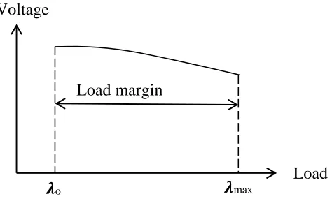
Figure 2.1: Load margin assessment, load vs. voltage
- The loading at base case
max - The Maximum Loading Point (MLP) value
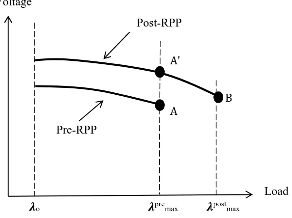
From the load margin assessment, the critical bus of a system and the maximum load it can provide could be also determined. The bus with the lowest load margin is called as the critical bus; the load margin improvement will be monitored at the critical bus. The proposed EP optimization technique with MLP maximization as the objective function have been used to implement pre and post RPP to conduct comparisons in terms of Maximum Loading Point (MLP) expansion and entire system losses [6]. Graphically, Figure 2.2 below shows the observation of Point A, A’ and B.
Load margin
Load
Figure 2.2: Comparison between pre and post RPP implementation.
Point A - MLP prior to the implementation of the RPP or Pre-RPP Point B - MLP obtained as a result of RPP or Post-RPP
The researcher in [10] stated that in order to ensure the system voltage profile is acceptable for system normal and post-contingency conditions, the voltage profile criteria needed to be observed as a practical operation. However, voltage is a poor indicator of proximity to system failure condition when power system is under stressed. Subsequently, the cooperation of voltage stability becomes significant in RPP [10].
Voltage
Load
o premax postmax
A A’
B Post-RPP
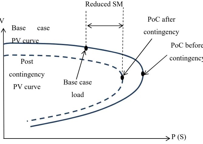
Figure 2.3: PV Curve for Base Case and Contingency
As referred to Figure 2.3, to avoid voltage instability or large scale voltage breakdown, shunt reactive power compensation is used to provide voltage support. In the Figure 2.3, voltage stability is usually identified by a P-V or S-V curve. The knee point of the curve is called the Point of Collapse (PoC), rapid voltage drop causes increment in PoC load which also known as the equilibrium point, where the respective Jacobian becomes singular. Beyond the PoC limit, power flow solution fails to converge, which express the voltage instability and can be associated with a saddle-node bifurcation point. Voltage problems in local area cause instabilities due to the reactive power shortage. Therefore, the objective to improve the static voltage stability margin (SM) defined as the displacement of saddle-node bifurcation point and base case operating point [10].
From thorough literature, several methods have been proposed for voltage stability enhancement in RPP solutions. Those methods were identified as conventional methods, heuristic methods and hybrid methods, which will be described in the following section.
V
P (S) Base case
PV curve Post contingency
PV curve
contingency
PoC before contingency
2.2 Conventional Method
Conventional or classical optimization techniques is found as a tool to optimize the RPP problem such as Linear Programming (LP), Nonlinear Programming (NLP), Mixed-Integer Nonlinear Programming (MINLP), and Interior Point (IP) methods have been used in RPP throughout years [2] [21]. The techniques are based on successive linearization which applied the first and second differentiations of objective function and its constraint equations as the search directions [1].
These conventional optimization methods are suitable for quadratic objective function which has only one minimum objective function. However, the formula of RPP problem is hyper quadratic functions, such as linear and quadratic presentation which produce a lot of local minima. As a result, the conventional optimization methods always results in divergence when solving RPP problem due to its only one local minimum [1].
Nonetheless, several classical methods as an alternative approach to solve various optimal reactive power flow problems from many researchers around the world. Thus, nonlinear reactive power optimization problem is also linearized using LP based technique in [21]. The benefits of this technique are fast solution, strong binding constraints enforcement, and low cost efficient packages. Meanwhile, NLP is proposed as a solution to optimum VAR planning problem, but undergoes slow convergence and capable to find only local optimum [21] [7]. Nevertheless, MINLP decomposition method significantly reduces the number of iterations [21]. Generally, these classical method have their own disadvantages which it has limited capability to solve the non-linear and non-convex power system problems with complex constraints [7].
2.3 Heuristic Method
(EA) are able to solve real-world problems, based on the natural selection principle and Charles Darwin rule of ‘survival of the fittest’ [31].
The heuristic method effectively overcame the classical algorithm weaknesses. Even though, these methods may be easily trapped in a local optimum when solving complex multimodal problems and its searching performance depends on the appropriate parameter settings but they have promising global searching ability and process multi-objective optimization problems [30]. However, single algorithm preferred outcome is difficult to be gained due to the numerous weaknesses like local extremum and slow convergence speed [3].
Heuristic algorithms also have been implemented to solve multi-objective reactive power flow problems in order to improve the inaccuracy by conventional techniques. As a reason, EP algorithm is used to overcome RPP problems and reduction of real power losses [3]. Besides that, Mixed Coding of Genetic Algorithm (MCGA) was proposed to minimize the system losses and presented a better result [3]. PSO also have been a solution for RPP problems, while modified PSO method is applied for RPP problems with an improvement in voltage stability margin [3]. DE algorithm is utilized effectively for both network losses minimization and voltage security problems [3].
2.4 Hybrid Method
Hybrid intelligent approaches have been proposed since a few years ago. These methods are created by hybridization of various methods to produce various types of intelligent system architectures [31]. The integration of different algorithms is mainly to overcome their individual weaknesses, by merging attributes and strengths of different approaches [31].