UNIVERSITI TEKNIKAL MALAYSIA MELAKA
INVESTIGATION OF MULTIPLE COOLING COIL EFFECT IN
HYDRONIC RADIANT COOLING SYSTEM FOR AIR
HANDLING UNIT (AHU) PURPOSES
This report is submitted in accordance with the requirement of Universiti Teknikal Malaysia Melaka (UTeM) for the Bachelor Degree of Engineering Technology
(Refrigeration and Air Conditioning System) with Honours
by
MUHAMMAD HAZWAN BIN ROSSLI B071310394
911019-14-6593
UNIVERSITI TEKNIKAL MALAYSIA MELAKA
BORANG PENGESAHAN STATUS LAPORAN PROJEK SARJANA MUDA
TAJUK: INVESTIGATION OF MULTIPLE COOLING COIL EFFECT IN HYDRONIC RADIANT COOLING SYSTEM FOR AIR HANDLING UNIT PURPOSES
SESI PENGAJIAN: 2015/16 Semester 1 Saya MUHAMMAD HAZWAN BIN ROSSLI
mengaku membenarkan Laporan PSM ini disimpan di Perpustakaan Universiti Teknikal Malaysia Melaka (UTeM) dengan syarat-syarat kegunaan seperti berikut:
1. Laporan PSM adalah hak milik Universiti Teknikal Malaysia Melaka dan penulis. 2. Perpustakaan Universiti Teknikal Malaysia Melaka dibenarkan membuat salinan
untuk tujuan pengajian sahaja dengan izin penulis.
3. Perpustakaan dibenarkan membuat salinan laporan PSM ini sebagai bahan pertukaran antara institusi pengajian tinggi.
4. **Sila tandakan ( )
TERHAD SULIT
TIDAK TERHAD
(Mengandungi maklumat yang berdarjah keselamatan atau kepentingan Malaysia sebagaimana yang termaktub dalam AKTA RAHSIA RASMI 1972)
(Mengandungi maklumat TERHAD yang telah ditentukan oleh organisasi/badan di mana penyelidikan dijalankan)
Alamat Tetap:
No 6, Jalan 16/3C
Taman Cheras Jaya, Batu 9 Cheras
43200 , Selangor Darul Ehsan.
Tarikh: ________________________
Disahkan oleh:
Cop Rasmi:
Tarikh: _______________________
DECLARATION
I hereby, declared this report entitled
“Investigation of Multiple Cooling Coil Effect in Hydronic Radiant Cooling System for Air Handling Unit (AHU) purposes”
is the results of my own research except as cited in references.
Signature : ………..
APPROVAL
This report is submitted to the Faculty of Engineering Technology of Universiti Teknikal Malaysia Melaka (UTeM) as a partial fulfillment of the requirements for the degree of Bachelor of Mechanical Engineering Technology (Refrigeration & Air-Conditioning Systems) (Hons.). The member of the supervisory is as follow:
………
i
ABSTRAK
ii
ABSTRACT
iii
DEDICATION
iv
ACKNOWLEDGEMENT
v
TABLE OF CONTENT
Abstrak i
Abstract ii
Dedication iii
Acknowledgement iv
Table of content v
List of Tables viii
List of Figures ix
List of Abbreviations, Symbols and Nomenclature xi
CHAPTER 1 INTRODUCTION
1.1 Background of the study 1
1.2 Problem Statement 3
1.3 Objective 4
1.4 Scope of Work 4
1.5 Thesis Outline 5
CHAPTER 2 LITERATURE REVIEW
2.1 Central Air Conditioning Cycle 6
2.1.1 Air Conditioning and Global energy demand 7
2.2 Air Handling Unit 9
2.2.1 Air Handling Unit Performances 10
2.2.2 Energy Consumption 11
2.3 Fan 12
2.3.1 Fan Selection 12
2.4 Cooling Coil 13
2.4.1 Coil placement inside the Air Handling Unit 14
2.5 Hydronic Radiant Cooling System 14
vi 2.5.3 Types of Hydronic Radiant Cooling System 16
2.5.4 Limitation 17
2.5.5 Energy Consumption of Hydronic Radiant Cooling System 17 2.5.6 Comparison between Hydronic Radiant Cooling and Air- 18
Conditioning System
2.6 Silica Gel 18
2.6.1 Absorbing and Removing Moisture 19
CHAPTER 3: METHODOLOGY
3.1 Flow chart 21
3.2 Design and preparation of prototype 22
3.3 Fabrication Process 23
3.3.1 Selection of Component and Material 23
3.3.2 Selection of Equipment 32
3.3.3 Procedures 33
3.4 Experimental Process 41
3.4.1 First experiment (Water temperature) 41
3.4.2 Second experiment (Effect of distance on temperature output 42 with single coil)
3.4.3 Third experiment (Effect of number of row cooling coil on the 43 temperature output)
3.4.4 Experimental Equipment 44
3.4.5 Experimental Procedure 46
CHAPTER 4 RESULT AND DISCUSSION
4.1 Result 49
4.1.1 Experiment 1: Effect of amount sodium chloride to water 50 Temperature
4.1.2 Experiment 2: Effect of Distance of Cooling Coil on temperature 53 Output
vii
4.2 Coefficient of Performances (COP) 64
4.3 Efficiency of the system 68
CHAPTER 5 CONCLUSION AND RECOMMENDATION
5.1 Summary of the Project 70
5.2 Achievement of Project Objective 71
5.3 Future Development 72
REFERENCES 73
viii
LIST OF TABLES
2.1 Typical coil air pressure drop 13
3.1 List of Equipment functions 32
3.2 Amount of Sodium Chloride 41
3.3 Experimental Procedure Process 46
ix
LIST OF FIGURES
2.1 Central system cycle 7
2.2 Energy usage of equipment in HVAC system 8
2.3 Air Handling Unit Flow 10
3.1 Flow Chart 21
3.2 Schematic diagram of complete system 22
3.3 Acrylic Sheet 23
3.4 Axial AC fan 24
3.5 Proton Waja Cooling Coil 24
3.6 Copper tube 25
3.7 AC water pump 25
3.8 Silica Gel 26
3.9 Insulator 26
3.10 Hollow Metal Bar 27
3.11 Zinc sheet 27
3.12 PVC Pipe 28
3.13 L bracket 28
3.14 Threaded Metal Bar 29
3.15 Plastic container box 29
3.16 Screw and Nut 30
3.17 Plywood 30
3.18 Fan Regulator 31
3.19 Electrical box 31
3.20 Schematic diagram of 3 cases (Effect of Distance on temperature output) 42 3.21 Schematic diagram of 2 cases (Effect of number of row cooling coil on 43
the temperature output)
3.22 Thermometer Fluke 44
3.23 RH data logger 45
xi
LIST OF ABBREVIATIONS, SYMBOLS AND
NOMENCLATURE
A Ampere/Area
AC Alternate Current AHU Air Handling Unit
C Celsius
Cfm Cubic feet per minute COP Coefficient of Performances
Cp Specific Heat
F Fahrenheit
Ft Feet
Fpm Feet per minute
HRC Hydronic Radiant Cooling
h Height
HVAC Heating, Ventilating and Air Conditioning
Hz Hertz
Inch Inches
Kg Kilogram
Kw Kilowatt
L Litre
l Length
m Meter
ṁ Mass flow rate
NaC1 Sodium Chloride PVC Polivinyl Chloride RH Relative Humidity Rpm Rotation per minute USB Universal Serius Bus
Q Heat
xii V Voltage/Velocity
W Width
ɳ Efficiency
ρ Density
1
CHAPTER 1
INTRODUCTION
The current chapter introduces the most important subtitles related to the project. However, the subtitles are the plan and the basic topics, which include background of the study, problem statement, objectives, scope of the project and thesis outline.
1.1 Background of the study
2 In recent years, a system that provide more comfortable thermal environment than conventional all-air system has been created. The system is designed to reduce energy consumption in the line with current modern technology. An alternative system is called Hydronic Radiant Cooling (HRC) which is using water as the transport medium(Colorado, 2010). It is becomes one of the significant solutions since it is able to reduce amount of air distribute in the buildings. HRC is normally install in ceiling, wall and building floor. Unlike the conventional air conditioning system, HRC does not use a vapour compression cycle that consume 40% of the total electrical consumption in the world (Westphalen, Koszalinski, & Little, 1999). Cold water are used to replace refrigerant gas as a cooling medium that is unlimited source, cheapest and also environmental friendly. The natural cooling provided by HRC is more acceptable range for thermal comfort.
In this current study, an Air Handling Unit (AHU) which are used in air-conditioning system will be design, fabricate in prototype and tested the application for cooling in Malaysia. HRC are connected to cooling coil to supply cold water as a cooling sources. Fan are required in AHU which performs the function of force and recycling the air present in the building space. The second important components of an AHU are the cooling elements which are used to allow cold water flow into the air-conditioning systems. The distance between fan and cooling coil, number of row, and oriental of the design must be considered because it will affect the AHU performances (A. P. Guide et al 1998). Selection of material for AHU casing are also are important parts to prevent heat loss and the types of insulation are selected. Drain pan are attached below the cooling coil to catches the condensate that drips off at the outside of the coil as the warm moist air passes over the coil. The cold water in the coil cooled the air and causing the moisture to condense on the outside of the coil.
3 consideration are output temperature and also relative humidity for controlling the humidity of the conditioned space. In order to control the humidity and dry bulb temperature, silica gel material is placed after cooling coil where the air inlet is supplied. Therefore, the experimental work will be carried out to confirm the suitability of this application in Malaysia.
1.2 Problem Statement
Hot climate in Malaysia led many building use air conditioning for comfort. The total energy consumption increase and cause a large impact on economy. Most of the existing air-conditioning in the market using vapour compression cycle compared to absorption cycle. Compressor is one of the basic components in the vapor compression cycle and it is assigned to compress the refrigerant into the system. It requires a high energy consumption to operate. It also generates noise and vibrations in the system that requires maintenance and this increase the annual cost.
4
1.3 Objective
In this current project, some targets has been select to focus on the studied. Therefore, the main objective of the current project are:
a) To study the possibilities of using Hydronic Radiant Cooling (HRC) as an alternative cooling system for Malaysia climate
b) To develop a prototype of Air Handling Unit to apply Hydronic Radiant Cooling in achieving desired temperature
c) To compare multiple row of cooling coil in demonstrate temperature and relative humidity data by applying silica gel.
1.4 Scope of Work
5
1.5 Thesis Outline
6
CHAPTER 2
LITERATURE REVIEW
Present literature review is summarized to survey topics that have more relevant to current study. The most important subtopics summarized for current Literature review are background, Air Handling Unit, fans, cooling coils, Hydronic radiant cooling system, acrylic and silica gel.
Therefore the background for current project is carried out and summarized to understand the basic idea of air conditioning system. Central air conditioning cycle is the attractive example which used in wide space. Air Conditioning and Global energy demand is considered as well.
2.1. Central Air Conditioning Cycle
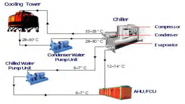
7 temperature or rely solely on air to cool the working fluid to near the dry-bulb air temperature (Christiansen, 2007). The arrangement of Central system cycle is shown in Figure 2.1.
Figure 2.1: Central system cycle
2.1.1 Air Conditioning and Global energy demand
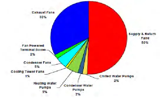
8 Figure 2.2: Energy usage of equipment in HVAC system
Using supply and return fans consume huge amount of energy compared to the other applications, because it used in almost 100% of system types as defined in (Westphalen et al., 1999) and as reported that. Normally, air distribution design resulting considerable pressure drop for filtration, cooling and heating coils, terminal boxes, and diffusers, and many of these fans operate at 100% power during all building operating hours
Improvements in equipment efficiency can help to reduce in building operating costs. Energy conservation in buildings is important because HVAC system is one of the primary energy users in buildings. Efficiency of AHU and air distribution systems can save amounts of energy, reduce operating costs and comply with widely used energy standards (ASHRAE Standard 90.1 2004) and building codes. The electricity sector involves the generation, transmission, and distribution of electricity. Carbon dioxide (CO2)
makes up the most of the greenhouse gas emissions from the sector, but smaller amounts of methane (CH4) and nitrous oxide (N2O) are also emitted.