USPEX
A
Version 1.9.2M1
Hardware Release Note
Contents s iii
D:\Docs\Gold\HW_Rel_Note\hwrn_bookTOC.fm; June 12, 1998 1:06 pm
Contents
Introduction ...1
Hardware Features Supported from 1.9.2 ...1
Hardware Features Supported from 1.9.1 ...2
Hardware Features Supported from 1.9 ...2
Hardware Features Supported from 1.8.1 ...2
Hardware Features Supported from 1.8 ...2
Hardware Features Supported from 1.7 ...3
Hardware Features Supported from 1.6.1 ...3
Hardware Features Not Supported with 1.9.2M1...3
Important Issues ...4
Processor Board Configurations ...5
NS 7000/500 Electrical and Power System Issues...6
Host Processor VII and VIII ...7
Network Processor III and IV...9
Memory Configurations...9
Network Interface Configurations ...10
Storage Processor IV and V ...12
Processor Board LEDs ...12
Host Processor ...12
Network Processor...12
ATM LEDs ...12
FDDI-SAS LEDs ...14
FDDI-DAS LEDs ...15
Quad Ethernet LEDs ...17
Network Cable Connections...18
Network Interface Numbering ...22
Ethernet Addressing...23
Network Cable Specifications ...25
Ethernet ...25
ATM ...25
FDDI...25
Connecting the NetServer to a Network ...26
NetServer Expansion Cabinet ...27
NS 7000/060 Environmental Requirements ...30
Space Requirements...30
NS 7000/060 Electrical Requirements...31
Grounding the NS 7000/060 Expansion Cabinet ...32
Connecting SCSI Cables...33
NS 7000/060 Expansion Cabinet SCSI Cabling...33
NS 7000/050 Expansion Cabinet SCSI Cabling...36
Drive Slot Numbering ...39
NS 7000/060 Power Supply Configurations and LEDs ...41
System Console...43
Setting Up the System Console ...43
Break Function ...44
Enabling the Delete Key...45
Configuring the PgUp and PgDn Keys for vi editor ...45
Using Diacritics for Key Functions...46
Setup Parameter Values for System Consoles ...46
Power-On Self Test (POST) and Boot Sequence ...47
Declaration of Conformity ...54
Introduction s 1
Introduction
The Version 1.9.2M1 Hardware Release Note describes NetServer™ hardware features and configurations supported in software Version 1.9.2M1. This release note updates the hardware information in the NS 7000 Model 150/250 Series Hardware Manual, NS 7000 Model 500 Series Hardware
Manual, NS 7000 Model 650 Series Hardware Manual, and NS 7000 Model 700 Series Hardware Manual for
customers upgrading from software Version 1.6.1 and later.
While this document includes hardware supported from previous software versions, not all hardware discussed in this release note is currently available from Auspex.
Additionally, this release note provides the following information:
s Documentation changes to the NS 7000™ family of products
s Declaration of Conformity for the NS 7000 NetServer product line
s Notice of VCCI Compliance
Refer to the Version 1.9.2M1 Software Release Note (part number: 850494 Rev B) for new software features and installation procedures. Refer to the System Manager’s Guide (part number: 850393 Rev A) for instructions on using the software.
The remainder of this section traces the development of hardware features from software Version 1.6.1 to present, and concludes with a section describing hardware features that are not supported in software Version 1.9.2M1. The remainder of this document provides sections explaining and expanding on the impact of those features, such as in areas of power requirements and network configurations.
Not all sections of this manual may apply to you depending on the software version running on your system. For example, if your NetServer came from the factory with Version 1.8 software, the hardware manuals for that system already include information regarding the NS 7000/060 expansion cabinet, which was first available with software Version 1.6.1.
Note: Information in this release note about Host Processor- or Storage Processor-attached extended storage devices is for reference only. Complete information on how to attach and operate extended storage devices ships separately with each device.
Note: Version 1.9.2M1 is a software maintenance release only. No new hardware is introduced with software Version 1.9.2M1.
Hardware Features Supported from 1.9.2
The following hardware features from software Version 1.9.2 are supported with software Version 1.9.2M1:
s Quad 10/100Base-T Ethernet network interface
s ACL 7/100 tape library
s NS 7000/080 expansion cabinet
Hardware Features Supported from 1.9.1
The following hardware features from software Version 1.9.1 are available with software Version 1.9.2M1:
s ATM Unshielded Twisted Pair (UTP) network interface
s Quad Ethernet network interface
s 12x CD-ROM drive
Hardware Features Supported from 1.9
The following hardware features from software Version 1.9 are supported with software Version 1.9.2M1:
s Host Processor (HP) VIII with 125-MHz SPARC CPU supporting up to 384 MB of memory
s Write Accelerator III with 8 MB of cache memory (SP V only)
s Full-duplex 100Base-T Ethernet network interface
s ACL 4/52 tape library (SP-attachable)
s DLT4700 mini-library (SP-attachable)
Hardware Features Supported from 1.8.1
The following hardware features from software Version 1.8.1 are supported with software Version 1.9.2M1:
s Network Processor (NP) IV supporting up 256 MB of memory
s Mixed NP configurations supporting up to 15 FDDI, 100Base-T, and ATM interfaces with the extended VME backplane (NS 7000/700 and NS 7000/800 Series only)
s 4X CD-ROM drive
s ACL 4/52 tape library (HP-attachable)
s DLT4000 tape drive (HP-attachable)
s DLT4700 mini-library (HP-attachable)
s Exabyte 8505XL tape drive
Hardware Features Supported from 1.8
The following hardware features from software Version 1.8 are supported with software Version 1.9.2M1:
s NP III supporting up to 256 MB of memory and the MVIC64 chip for increased VME bandwidth
s SP V with 2 MB of memory
s SP IV with 1 MB of memory
s SP III-E with 1 MB of memory
Introduction s 3
s Write Accelerator II with 2 MB of memory
s DLT4000 tape drive (SP-attachable)
s 4-GB disk drive
s ATM fiber network interface
Hardware Features Supported from 1.7
The following hardware features from software Version 1.7 are supported with software Version 1.9.2M1:
s WarmStart boot feature that bypasses lengthy power-on board-level hardware and memory test procedures, speeding up overall boot time for the system
s Support for up to two NS 7000/060 expansion cabinets
Hardware Features Supported from 1.6.1
The following hardware features from software Version 1.6.1 are supported with software Version 1.9.2M1:
s NS 7000/060 NetServer expansion cabinet with up to 84 drive slots
s DEC VT510 system console
Hardware Features Not Supported with 1.9.2M1
The following hardware features are not supported with software Version 1.9.2M1:
s Half-duplex 100Base-T Ethernet network interface
s 10Base-T Ethernet (Buf-E) network interface
s Auspex Primary Memory (APM) boards
s ATM SBus cards installed in HP boards
s Ethernet Processor (EP) boards
s File Processor (FP) boards
s HP II through HP VI boards
s NP I and NP II boards
s SP I, SP II, and SP III boards
Important Issues
The following issues apply to servers running software Version 1.9.2M1:
s The NS 7000/500 Series NetServer can accept a total of three NP boards and three SP boards (see the following note). This is a power subsystem limitation (refer to section “NS 7000/500 Electrical and Power System Issues” on page 6).
s The NS 7000/650 Series NetServer can accept a total of four NP boards and four SP boards. This is a card cage slot limitation. However, the NS 7000/650 Series NetServer card cage can be upgraded to increase the total number of NP and SP boards from 8 to 10.
s The NS 7000/700 Series NetServer can accept a total of 10 NP and SP boards (see the following note).
Processor Board Configurations s 5
Processor Board Configurations
This section describes the processor board configurations for the following series of NetServers:
s NS 7000/800
s NS 7000/700
s NS 7000/650
s NS 7000/500
s NS 7000/250
s NS 7000/150
Each processor board is described in the following sections. Systems upgrading to software Version 1.9.2M1 must upgrade hardware to match the configurations listed in Table 1.
Table 1. Processor board configurations supported by software Version 1.9.2M1
Processor board Minimum configuration Maximum configuration Description Host Processor
(HP VIII, HP VII)
1 1 The HP VIII includes a 125-MHz SPARC
CPU. The HP VII includes a 90-MHz SPARC CPU.
Each HP supports up to 384 MB of memory. For more information on HP memory configurations, refer to Table 3 on page 7.
Network Processor (NP IV, NP III)
1 5 The NP III and NP IV have 64 to 256 MB of
memory for protocol processing, file processing, and I/O cache memory. For more information on NP memory configurations, refer to Table 4 on page 9. Each NP supports 100Base-T Ethernet, Quad Ethernet, Quad 10/100Base-T Ethernet, FDDI, and ATM network
interfaces*. Refer to Table 5 on page 10 for more information on supported network interfaces.
* Some interface types require optional software (refer to the documentation provided on the Auspex Premier Software Series CD-ROM for more information).
Storage Processor (SP V, SP IV, SP III-E†)
† The SP III-E supports drives in NS 7000/500 base cabinets and NS 7000/050 expansion cabinets only.
1 5 The SP V supports the Write Accelerator III board, which has 8 MB of memory. The SP III-E and SP IV support the Write Accelerator II board, which has 2 MB of memory.
NS 7000/500 Electrical and Power System Issues
The new Auspex processor boards require more DC power than the NS 7000/500 power subsystem can support, which means certain NS 7000/500 configurations require electrical changes and power system upgrades. Some configurations require changing the AC input voltage, others require upgrading the base cabinet (contact your Auspex service representative for assistance). Refer to Table 2 for NS 7000/500 upgrades to determine configuration requirements.
Table 2. NS 7000/500 configuration requirements
To improve the NS 7000/500 power subsystem, Auspex recommends changing the voltage from 100 VAC (100 to 120 VAC nominal range) to 200 VAC (200 to 240 VAC nominal). Increasing the voltage decreases the input current, which reduces stress on the AC input section of the power subsystem, wiring, and connections.
AC Input Current (When VIN = 100V)
+5VDC
Output Current ≤ 16 Amps > 16 Amps
≤ 130 Amps
(seven or fewer processor boards)
No action required
Change AC input voltage from 100 VAC to 200 VAC (200–240 VAC nominal)
> 130 Amps
(eight or more processor boards)
Host Processor VII and VIII s 7
Host Processor VII and VIII
The HP VII and HP VIII have the following features:
s 90-MHz (HP VII) and 125-MHz (HP VIII) SPARC CPU
s Up to 384 MB of memory (see Table 3 for HP memory configurations).
s Support for up to three SBus cards (except ATM)
Note: The HP supports three single, one double and one single, or one triple SBus card.
s Serial connections to the TTYA and TTYB ports.
s Integrated Mbus design allowing future upgrades to the CPU
[image:11.612.73.540.302.517.2]s Support for up to seven SCSI devices
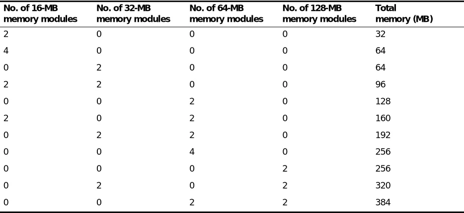
Table 3 lists the supported HP memory configurations.
Note: HP memory modules must be installed in pairs of 16, 32, 64, or 128-MB.
Table 3. HP memory configurations No. of 16-MB
memory modules
No. of 32-MB memory modules
No. of 64-MB memory modules
No. of 128-MB memory modules
Total
memory (MB)
2 0 0 0 32
4 0 0 0 64
0 2 0 0 64
2 2 0 0 96
0 0 2 0 128
2 0 2 0 160
0 2 2 0 192
0 0 4 0 256
0 0 0 2 256
0 2 0 2 320
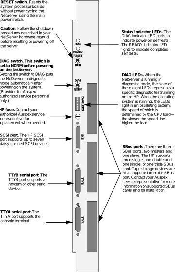
Figure 1 illustrates the HP front panel and connections.
Figure 1. HP front panel
DIAG READY RESET RUN DIAG NORM DIAG LEDS SCSI TTYB TTYA
SCSI port. The HP SCSI
port supports up to seven daisy-chained SCSI devices.
RESET switch. Resets the
system processor boards without power cycling the NetServer using the main power switch.
Caution: Follow the shutdown
procedures described in your NetServer hardware manual before resetting or powering off the server.
TTYB serial port. The
TTYB port supports a modem or other serial device.
TTYA serial port. The
TTYA port supports the console terminal.
DIAG switch. This switch is set to NORM before powering on the NetServer.
Setting the switch to DIAG puts the NetServer in diagnostic mode automatically after powering on the system. (Provided for Auspex authorized service personnel only.)
HP fuse. Contact your
authorized Auspex service representative for replacement when needed.
DIAG LEDs. When the
NetServer is running in diagnostic mode, the state of these eight LEDs represents a specific diagnostic test running on the HP. When the operating system is running, the LEDs light in an oscillating pattern, the speed of which is determined by the CPU load— the slower the speed, the higher the load.
SBus ports. There are three
SBus ports: two masters and one slave. The HP supports three single, one double and one single, or one triple SBus card. Tape storage devices are also supported from the SBus port. Contact your Auspex service representative for more information on supported SBus cards and for installation.
Status indicator LEDs. The
Network Processor III and IV s 9
Network Processor III and IV
The NP III and NP IV have the following features:
s Up to 256 MB of memory
s Up to 100 MB-per-second VME transfer speed when operating in conjunction with SP V
s Support for the following network interfaces: – Quad 10/100Base-T Ethernet
– Quad Ethernet (four 10Base-T Ethernet ports) – 100Base-T Ethernet (full-duplex)
– FDDI-SAS (fiber or MLT-3) – FDDI-DAS (fiber)
– ATM (fiber or UTP)
Memory Configurations
The NP III and NP IV have 64–256 MB of memory for protocol, file processing, and I/O cache memory. Each NP has four or eight SIMMs of either 16 MB or 32 MB each. Refer to Table 4 for a list of memory configurations supported by software Version 1.9.2M1.
Note: SIMMs must be installed in groups of four of the same capacity.
Table 4. NP III and NP IV memory configurations
No. of 16-MB SIMMs No. of 32-MB SIMMs Total memory (MB)
4 0 64
8 0 128
0 4 128
4 4 192
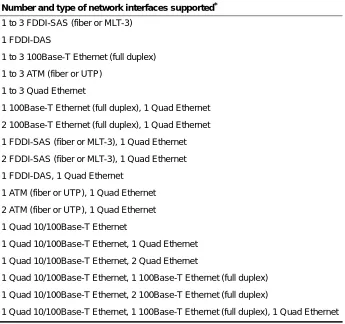
Network Interface Configurations
Table 5 lists the supported NP network interface configurations.
Table 5. Network interface configurations supported by software Version 1.9.2M1 Number and type of network interfaces supported*
* Each Quad Ethernet network interface has four 10Base-T ports.
1 to 3 FDDI-SAS (fiber or MLT-3)
1 FDDI-DAS
1 to 3 100Base-T Ethernet (full duplex)
1 to 3 ATM (fiber or UTP)
1 to 3 Quad Ethernet
1 100Base-T Ethernet (full duplex), 1 Quad Ethernet
2 100Base-T Ethernet (full duplex), 1 Quad Ethernet
1 FDDI-SAS (fiber or MLT-3), 1 Quad Ethernet
2 FDDI-SAS (fiber or MLT-3), 1 Quad Ethernet
1 FDDI-DAS, 1 Quad Ethernet
1 ATM (fiber or UTP), 1 Quad Ethernet
2 ATM (fiber or UTP), 1 Quad Ethernet
1 Quad 10/100Base-T Ethernet
1 Quad 10/100Base-T Ethernet, 1 Quad Ethernet
1 Quad 10/100Base-T Ethernet, 2 Quad Ethernet
1 Quad 10/100Base-T Ethernet, 1 100Base-T Ethernet (full duplex)
1 Quad 10/100Base-T Ethernet, 2 100Base-T Ethernet (full duplex)
Network Processor III and IV s 11
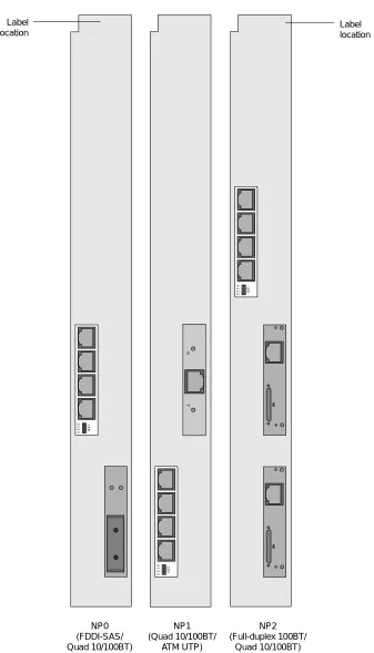
Figure 2 shows an example of network interfaces on NP boards.
Figure 2. Example of network interfaces on NP boards
NP0 (FDDI-SAS/ Quad 10/100BT)
NP1 (Quad 10/100BT/
ATM UTP)
NP2 (Full-duplex 100BT/
Quad 10/100BT)
MII
MII
Label location Label
location
RT
0 1 2 3
LED
0 1 2 3 LED
0 1 2 3
Storage Processor IV and V
The SP IV and SP V have the following features:
s Up to 100 MB-per-second VME transfer speed
s Up to 2 MB of memory
s Support for Write Accelerator II and III boards
Processor Board LEDs
This section describes the LED functions on the Host Processor and Network Processor boards.
Host Processor
The Host Processor has three LEDs:
s DIAG
s READY
s Diagnostic
The DIAG LED lights green, indicating the system is performing Power-On Self Test (POST). The READY LED lights green after the system successfully completes self test.
The Diagnostic LEDs light green, representing a specific diagnostic test running on the HP when the NetServer is in diagnostic mode. When the operating system is running, the LEDs light in an
oscillating pattern, the speed of which is determined by the CPU load—the slower the speed, the higher the load.
By monitoring these LEDs, you can determine if the HP is functioning properly (refer to Figure 1 on page 8 for location of the HP LEDs).
Network Processor
The ATM, FDDI-SAS, FDDI-DAS, and Quad Ethernet SBus cards on an NP board each have their own set of LEDs. The LEDs and their functions are described as follows.
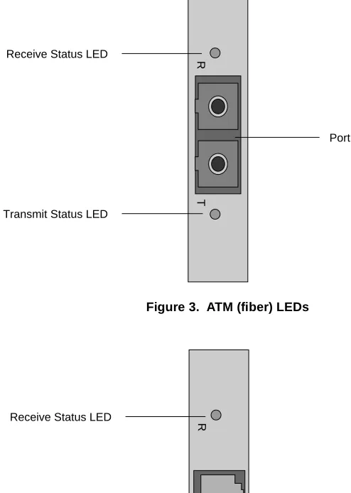
ATM LEDs
ATM SBus cards have two LEDs:
s The Receive Status LED lights green when receiving data or red when there is no carrier. If the light is red, check to see if the cable is properly connected. The normal condition is off, meaning device is idle and ready to receive.
s The Transmit Status LED lights green when transmitting data or yellow when a SONET alarm condition is declared. The SONET alarm indicates trouble with the receiving device. If the light is yellow, check to see if cable is properly connected. The normal condition is off, meaning device is idle and ready to transmit.
Processor Board LEDs s 13 Figure 3. ATM (fiber) LEDs
Figure 4. ATM (UTP) LEDs
Receive Status LED
Transmit Status LED
Port
RT
RT
Receive Status LED
Transmit Status LED
FDDI-SAS LEDs
FDDI-SAS SBus cards have two LEDs:
s The Status LED lights green when the card passes internal diagnostics and is functioning properly.
[image:18.612.175.434.212.692.2] [image:18.612.186.423.219.435.2]s The RingOP LED lights green when the card is connected to the ring. If this LED is not lit, check that cables are properly connected and you have followed the proper procedure for powering on the NetServer.
Figure 5 shows the location of LEDs on the fiber FDDI-SAS SBus cards. Figure 6 shows the location of LEDs on the MLT-3 FDDI-SAS SBus cards.
Figure 5. FDDI-SAS (fiber) LEDs
Figure 6. FDDI-SAS (MLT-3) LEDs
RingOP LED Status LED
Port
RingOP LED Status LED
[image:18.612.184.423.467.681.2]Processor Board LEDs s 15
FDDI-DAS LEDs
FDDI-DAS SBus cards have two LEDs:
s The STATUS LED lights green when the SBus card passes its internal diagnostics and is functioning properly.
s The RingOP LED lights green when the card is connected to the ring. If this LED is not lit, check that cables are properly connected and you have followed the proper procedure for powering on the NetServer.
Table 6 lists LED states that can occur during operation.
Table 6. RingOP LED indicators on the FDDI-DAS SBus card
RingOP B* - Off RingOP B - Green RingOP B - Orange RingOP A* -
Off
* RingOP A refers to the RingOP LED for port A. RingOP B refers to the RingOP LED for port B.
Ring is not operational. Station is in WRAP_B, ring is operational.
Ring is not operational. The station connected to the PHY B attempted to connect but failed.
RingOP A - Green
Station is in WRAP_A, B is not connected.
Station is in THRU mode, ring is operational.
Station is in WRAP_A. The station connected to PHY B attempted to connect but failed.
RingOP A - Orange
Ring is not operational. The station connected to PHY A attempted to connect but failed.
Station is in WRAP_B. The station connected to PHY A attempted to connect but failed.
Figure 7 shows the location of LEDs on FDDI-DAS SBus cards.
Figure 7. FDDI-DAS LEDs
RingOP LED Status LED
Port B RingOP LED Status LED
Port A
Processor Board LEDs s 17
Quad Ethernet LEDs
Quad Ethernet and Quad 10/100Base-T Ethernet SBus cards have four green LEDs that light to indicate occurring activity through the ports. The LEDs are labeled 0 through 3. The LED labeled 0 corresponds with port 3 and the LED labeled 3 corresponds with port 0.
[image:21.612.245.367.229.464.2]Note: Quad Ethernet network interface numbering does not correspond with the LEDs on the SBus card. Refer to “Network Interface Numbering” on page 22 for more information on Quad Ethernet network interface numbering.
Figure 8 shows the location of the LEDs on Quad Ethernet and Quad 10/100Base-T Ethernet SBus cards.
Figure 8. Quad Ethernet LEDs
0 1 2 3 LED
LEDs Port 3
Port 2
Port 1
Network Cable Connections
This section is provided as a reference to show the network cable connections to ATM, Ethernet, and FDDI ports on NP boards.
Note: The FDDI-SAS port for a fiber connection is a single-attach station of “Type S.” Connect the FDDI-SAS to a “Type M” FDDI concentrator port only.
The FDDI-DAS ports are a dual-attach station. Connect directly to the primary and secondary FDDI rings or to “Type M” ports on two concentrators in a dual-homed configuration.
Figures 9 through 16 illustrate connections to Ethernet, FDDI and ATM ports on NP boards.
Figure 9. Connection to Quad 10/100Base-T Ethernet ports
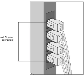
Network Cable Connections s 19 Figure 10. Connection to Quad Ethernet ports
Figure 11. Connection to full-duplex 100Base-T Ethernet ports
Quad Ethernet connectors
Full-duplex 100Base-T Ethernet connectors
PORT
2
PORT
Figure 12. Connection to FDDI (fiber) ports
Figure 13. Connection to FDDI (MLT-3) ports
FDDI (fiber) connectors FDDI (fiber)
connectors
[image:24.612.181.402.397.673.2]Network Cable Connections s 21 Figure 14. Connection to ATM (fiber) ports
Figure 15. Connection to ATM (UTP) ports
ATM (fiber) connectors
RT
RT
ATM (UTP) connectors
RT
[image:25.612.183.403.391.669.2]Network Interface Numbering
Network interface numbering is used to configure the system software. Each interface numbering scheme is described as follows.
Quad 10/100Base-T Ethernet Quad 10/100Base-T Ethernet interfaces are numbered ahme0 to ahmen, where 0 is the lower Ethernet port closest to the HP, and n is the upper Ethernet port farthest from the HP.
Quad Ethernet Quad Ethernet interfaces are numbered aqe0 to aqen, where 0 is the lower Ethernet port closest to the HP, and n is the upper Ethernet port farthest from the HP.
Full-duplex 100Base-T Full-duplex 100Base-T interfaces are numbered ahme0 to ahmen, where 0 is the lower Ethernet port closest to the HP, and n is the upper Ethernet port farthest from the HP.
FDDI FDDI interfaces are numbered afddi0 to afddin, where 0 is the lower FDDI port closest to the HP, and n is the upper FDDI port farthest from the HP.
Note: In DAS network configurations, only one port is assigned an interface number although two ports exist on the FDDI-DAS SBus card.
ATM Each ATM port supports three types of interfaces: 1 FORE IP primary interface, 4 Classical IP virtual interfaces, and 16 LANE Client (LEC) interfaces. Refer to Table 7 for an example of the network numbering for these interfaces.
Table 7 shows an example of ATM network interface numbering on a NetServer with two NP boards (NP0, NP1), each having two ATM SBus adapters (0, 1 and 2, 3).
Table 7. ATM network interface numbering NP
board no.
ATM SBus adapter no.
FORE IP
primary interfaces
Classical IP virtual interfaces
LANE Client interfaces
0 0 afa0 aqa0, aqa1, aqa2, aqa3 ael0 – ael15
0 1 afa1 aqa4, aqa5, aqa6, aqa7 ael16 – ael31
1 2 afa2 aqa8, aqa9, aqa10, aqa11 ael32 – ael47
Network Cable Connections s 23
Ethernet Addressing
[image:27.612.74.254.165.386.2]Auspex assigns unique network addresses (starting with 00:00:3c) to the Ethernet ports to identify each interface. The interfaces are numbered from bottom to top.
Table 8 shows an example of the Quad 10/100Base-T Ethernet addressing shown in Figure 16 on page 24.
Table 8. Quad 10/100Base-T Ethernet addressing Interface no. Network address
ahme11 00:00:3c:99:99:0B
ahme10 00:00:3c:99:99:0A
ahme9 00:00:3c:99:99:09
ahme8 00:00:3c:99:99:08
ahme7 00:00:3c:99:98:07
ahme6 00:00:3c:99:98:06
ahme5 00:00:3c:99:98:05
ahme4 00:00:3c:99:98:04
ahme3 00:00:3c:99:97:03
ahme2 00:00:3c:99:97:02
ahme1 00:00:3c:99:97:01
ahme0 00:00:3c:99:97:00*
Figure 16. Example network interface numbering on the NP boards NP0 (FDDI-SAS/ Quad 10/100BT) NP1 (Quad 10/100BT/ ATM UTP) NP2 (FDX 100BT/ Quad 10/100BT) MII MII Label location Label location RT afddi0 ahme0 ahme1 ahme2 ahme3 ahme5 ahme4 ahme6 ahme7 ahme0 afa0
aqa0 - aqa3 ael0 - ael15
ahme1 NP0 Quad 10/100Base-T Ethernet NP1 ATM NP1 Quad 10/100Base-T Ethernet ahme9 ahme8 ahme10 ahme11 NP2 Quad 10/100Base-T Ethernet
0 1 2 3
LED
0 1 2 3
LED
Network Cable Specifications s 25
Network Cable Specifications
The following network cable specifications are provided for reference only. Auspex does not supply network cables.
Ethernet
Ethernet connectors use data grade, Shielded Twisted Pair (STP) or Unshielded Twisted Pair (UTP) cables with RJ-45 connectors, or fiber cables with Media Independent Interface (MII) connectors.
ATM
ATM fiber connectors use 155-Mbps, multimode, OC-3 fiber cables with SC-type connectors, or UTP, category 5 cables with RJ-45 connectors. If your site uses ST-type connectors, you need ST-to-SC converters.
FDDI
FDDI connectors use 50–125-micron, multimode, category 5 cables with standard FDDI MIC connectors; or category 5, STP or UTP cables with RJ-45 connectors.
Recommendation: Auspex recommends using cables with EIA/TIA 568B wiring.
Table 9 lists the cable pin and pair assignments for EIA/TIA 568B cable connectors.
Table 9. EIA/TIA 568B cable pin and pair assignments
Pin Pin Pair Color
1 8 2 white/orange
2 7 2 orange
3 6 3 white/green
4 5 1 blue
5 4 1 white/blue
6 3 3 green
7 2 4 white/brown
Connecting the NetServer to a Network
This section describes how to connect the NetServer to a network. It assumes the appropriate network is installed at your site, and you have the proper network cables to complete the procedure.
Note: Auspex does not supply network cables (refer to “Network Cable Specifications” on page 25 for a list of recommended cables).
To connect the NetServer to a Network
1. Open the back door of the base cabinet. 2. Put on the antistatic wrist strap.
3. For NS 7000/500, NS 7000/650, NS 7000/700, and NS 7000/800 Series NetServers, route each end of the network cable through the opening in the PDU at the back of the cabinet (see Figure 17). In raised-floor environments, cables can be routed through the floor panel of the server. Contact your authorized Auspex service representative for assistance.
[image:30.612.134.480.333.578.2]4. For NS 7000/150 and NS 7000/250 Series NetServers, open the back door, and route each end of the network cables to the cardcage.
Figure 17. Routing cables to the NetServer
5. Attach each network cable to the appropriate connector on the NP boards. Hang up the wrist strap, and close the back door of the base cabinet.
6. Power on the NetServer.
7. If necessary, run the NSconfig command, and update the appropriate fields (refer to the System
Manager’s Guide for more information).
This completes the procedure for connecting the NetServer to a network.
Serial port B
Serial port A
Console cable
NetServer Expansion Cabinet s 27
NetServer Expansion Cabinet
This section describes the NS 7000/060 expansion cabinet supported with your NetServer base cabinet.
Note: For information on the NS 7000/080 expansion cabinet, which is supported with the NS 7000/800 Series NetServer, refer to the NS 7000 Model 800 Series Hardware Manual.
The NetServer supports up to two expansion cabinets.
Table 10 lists the supported expansion cabinet configurations.
The NS 7000/060 expansion cabinet supports 3.5-inch disk drives and 5.25-inch half-height tape and CD-ROM drives. The expansion cabinet supports up to 84 drives. The NS 7000/060 expansion cabinet contains four types of 19-inch rackmountable subassemblies:
s Disk drive racks (up to 12)
s PDU
s Power supply enclosure with power supply installed. As an option, a redundant power supply can be installed
Each NS 7000/060 expansion cabinet requires up to two SP V boards in the cardcage. The SP V has six parallel SCSI channels for disk, tape, and CD-ROM drives and an optional Write Accelerator board to enhance NFS write operations. Each SP supports up to 42 drives.
Note: If you need to connect an expansion cabinet to the base cabinet, contact your authorized Auspex service representative.
For general unpacking instructions, refer to your hardware manual.
Warning: The NS 7000/060 weighs approximately 500 pounds when empty. Do not attempt to move or uncrate the expansion cabinet unless you have someone to assist you. Any attempt to uncrate the expansion cabinet alone could result in injury.
For installation at customer sites with raised flooring, the expansion cabinet has a floor access panel, allowing the NetServer cabling to pass through the hole in the floor of the cabinet. For assistance with removing the floor access panel, contact your authorized Auspex service representative.
Figure 18 and Figure 19 show the front and back views of the NS 7000/060 expansion cabinet, respectively.
Note: The NS 7000/060 expansion cabinet has drive racks in both the front and back.
Table 10. Supported expansion cabinet configurations NetServer expansion cabinet configurations
Base cabinet + one NS 7000/060 expansion cabinet
Base cabinet + one NS 7000/050 expansion cabinet
Base cabinet + two NS 7000/060 expansion cabinets
Figure 18. NS 7000/060 expansion cabinet subassemblies (front)
System chassis Side panel
Lower front door panel Upper front door panel
Disk drive (in carrier)
Drive rack
Power supplies
AC OKDCOKALM+5VD - ++12VD - +VOLT ADJ+5V +12V AC
OKDCOKALM+5VD - ++12VD - + VOLT ADJ+5V +12V AC
NetServer Expansion Cabinet s 29 Figure 19. NS 7000/060 expansion cabinet subassemblies (back)
Back door panel
PDU Drive rack
Main power switch Access panel
NS 7000/060 Environmental Requirements
Operate the NetServer in a temperature-controlled, contaminant-free atmosphere within the recommended levels of humidity. Table 11 lists the necessary environmental conditions.
Note: The NetServer can operate at an altitude of up to 10,000 feet (3,000 m). However, the maximum operating temperature at an altitude between 7,000 feet (2,150 m) and
10,000 feet (3,000 m) is 86°F (30°C).
Space Requirements
Place the NS 7000/060 in a location no less than three feet from the nearest wall or other equipment (except for the base cabinet). Three feet of clearance allows easy access to the front and back of the server and permits adequate air circulation around the equipment.
[image:34.612.74.257.521.591.2]You must allow enough space at the installation site, including three feet of clearance on all sides, for the base cabinet and expansion cabinets to stand side by side, approximately two inches apart.
Table 12 lists the dimensions of the NS 7000/060 expansion cabinet. The weight shown is for a fully configured cabinet.
Table 11. NS 7000/060 Environmental requirements Minimum Maximum Operating temperature 40° F (5° C) 104° F (40° C)
Storage temperature 32° F (0° C) 150° F (65° C)
Operating altitude 0 feet (0 m) 7,000 feet (2,150 m)
Storage altitude 0 feet (0 m) 40,000 feet (12,000 m)
Operating humidity (noncondensing at 40° C)
20% 80%
Nonoperating humidity (noncondensing at 40° C)
10% 90%
Audible noise N/A 75 dB
Table 12. NS 7000/060 expansion cabinet dimensions Height 77 inches (195 cm)
Width 24 inches (61 cm)
Depth 39.5 inches (100 cm)
NetServer Expansion Cabinet s 31
NS 7000/060 Electrical Requirements
The NS 7000/060 expansion cabinet requires an electrical power source that is free of surges and other irregularities. The equipment must be adequately grounded to protect it from electrostatic interference during operation. Maintaining proper environmental humidity also helps reduce the risk of
electrostatic damage.
Caution: Power the expansion cabinet from a different circuit than the base cabinet to prevent electrical power surges.
Table 13 and Table 14 list the electrical power requirements and specifications for the NS 7000/060 expansion cabinet.
Caution: The NS 7000/060 expansion cabinet only accepts a nominal input voltage range of 200 to 240 VAC.
Caution: For proper air flow and EMI reduction, operate the NS 7000/060 expansion cabinet with the doors closed and all access panels in place.
Table 13. NS 7000/060 electrical power requirements Expansion cabinet (84 drives)
2,250 W
2.250 KVA
7,700 BTUs/Hour
Table 14. NS 7000/060 electrical specifications Nominal input voltage range 200–240 VAC
Operating input voltage range 180–264 VAC
Current rating 16 A
Service current rating 20 A
Frequency 50–60 ±3 Hz
Inrush current 20 A peak max per power supply (up to three power supplies supported)
Power factor 0.98
Turn-on time AC to DC ≈ 3 seconds
Electromagnetic Immunity (EMI) filter (conducted)
Class A
Grounding the NS 7000/060 Expansion Cabinet
After you unpack the NS 7000/060 NetServer cabinet and place it in its final location, you must plug the power cord into a 16-amp outlet to create a ground path for the antistatic wrist strap.
In the United States, Canada, and Mexico, the NS 7000/060 is shipped with an L6-20P plug. International configurations (except for Canada and Mexico) are shipped without a plug. The customer is responsible for providing a plug appropriate for the wall outlet.
Warning: The wiring at your site must provide for ground fault protection to prevent electrical shock.
To create a ground path
1. Locate the main power switch on the PDU inside the back door at the bottom of the expansion cabinet. Set this switch to OFF (O) (see Figure 20).
Caution: Use the main power switch on the PDU only. The switch at the top of each power supply located at the front of the cabinet should always be turned to ON (—).
Figure 20. Locating the power switch on the NS 7000/060
2. Locate the power cable, which is coiled on top of the panel covering the power supply.
3. Cut the red tie-wraps to release the power cable, and plug the appropriate end to the back of the PDU. The plug on the PDU is located to the left of the main power switch.
4. Tighten the strain relief surrounding the plug at the PDU. 5. Make sure power to the system is off.
6. Plug the power cable to a separate 16-amp grounded outlet.
Caution: Do not power on the expansion cabinet at this time. You connected the power cable only to provide a ground path for the antistatic wrist strap. For instructions on powering on the NetServer, refer to your hardware manual.
NetServer Expansion Cabinet s 33
Connecting SCSI Cables
This section explains how to route SCSIcables from each expansion cabinet to the base cabinet, and connect the cables to SP boards in the base cabinet. The procedures in this section assume the base cabinet and expansion cabinet are connected.
Note: If you need to connect an expansion cabinet to the base cabinet, contact your authorized Auspex service representative.
The SCSI cables from the NS 7000/060 expansion cabinet must be connected to an SP IV or SP V in the base cabinet. The SCSI cables from the NS 7000/050 expansion cabinet must be connected to an SP III-E in the base cabinet. The following sections describe these connections.
NS 7000/060 Expansion Cabinet SCSI Cabling
Each NS 7000/060 expansion cabinet is shipped with 12 SCSI cables installed inside the cabinet. The following procedure explains how to connect the SCSI cables to the SP IV or SP V boards in the base cabinet. The procedure assumes that the base cabinet and the expansion cabinet are connected.
Figure 21 on page 35 shows an NS 7000/060 expansion cabinet connected to an NS 7000/700 base cabinet.
To connect the SCSI cables to the base cabinet
1. Locate the SCSI drive cables tie-wrapped to the left side of the expansion cabinet inside the back door.
2. Cut the red tie-wraps securing the cables.
3. Route the free end of each SCSI cable through the open side of the expansion cabinet and into the open side of the base cabinet.
4. Gently pull the cable in through the opening, being careful to avoid bending it in a tight radius. Leave a small amount of slack in the cable inside the expansion cabinet.
5. Connect each cable to the SP IV or SP V connector indicated on the label affixed to the cable.
Table 15 lists the cable connections to an SP IV or SP V from drive racks in the first and second NS 7000/060 expansion cabinets (refer to “Drive Slot Numbering” on page 39 for the drive rack numbering scheme).
Figure 23 on page 38 illustrates the SCSI cabling between the first NS 7000/060 expansion cabinet and the NS 7000/700 base cabinet.
Table 15. SCSI connections for NS 7000/060 expansion cabinets First expansion cabinet Second expansion cabinet Drive
rack no.
SP V or SP IV connector*
* SP1 and SP2 are located in slots 13 and 14, respectively.
Drive rack no.
SP V or SP IV connector†
† SP3 and SP4 are located in slots 3 and 4, respectively.
1 SP1 J1 1 SP3 J1
2 SP1 J2 2 SP3 J2
3 SP1 J3 3 SP3 J3
4 SP1 J4 4 SP3 J4
5 SP1 J5 5 SP3 J5
6 SP1 J6 6 SP3 J6
7 SP2 J1 7 SP4 J1
8 SP2 J2 8 SP4 J2
9 SP2 J3 9 SP4 J3
10 SP2 J4 10 SP4 J4
11 SP2 J5 11 SP4 J5
Figure 22. SCSI cabling from the first NS 7000/060 expansion cabinet
NS 7000/050 Expansion Cabinet SCSI Cabling
One NS 7000/050 expansion cabinet can be connected to the NetServer as an option. The expansion cabinet is shipped with twelve SCSI drive cables. The following procedure explains how to connect SCSI cables to the SP III-E board in the base cabinet. The procedure assumes the base cabinet and expansion cabinet are connected.
Note: The NS 7000/050 expansion cabinet must be installed as the first expansion cabinet. This is to the right of the base cabinet when viewed from the back.
To connect SCSI cables to the SP III-E board in the base cabinet
1. Locate the SCSI drive cables tie-wrapped to the left side of the expansion cabinet inside the back door.
2. Cut the red tie-wraps securing the cables.
J5
J4
J3
J2
J1 J6
SP0 SP1 SP2
NS 7000/700 base cabinet (front)
Base cabinet (back)
NS 7000/060 expansion cabinet (front)
NS 7000/060 expansion cabinet (back)
Rack 5
Rack 6
Rack 11
Rack 12 Rack 1
Rack 2
Rack 3
Rack 4
Rack 7
Rack 8
Rack 9
Rack 10 Rack 1
Rack 2
Rack 3
Rack 4
Rack 5
Rack 6
NetServer Expansion Cabinet s 37
3. Route the free end of each SCSI cable through the open side of the expansion cabinet and into the open side of the base cabinet.
4. Gently pull the cable in through the opening, being careful to avoid bending it in a tight radius. Leave a small amount of slack in the cable inside the expansion cabinet.
[image:41.612.74.258.240.464.2]5. Connect each cable to the SP III-E connector indicated on the label affixed to the cable.
Table 16 lists all cable connections to the SP III-E board from drive racks in the NS 7000/050 expansion cabinet.
Note: Drive racks 3, 4, 7, and 8 are not listed in the table because they are daisy-chained from racks 1, 2, 5, and 6, respectively, and are not connected directly to an SP III-E board.
Figure 23 shows the SCSI cabling between the NS 7000/050 expansion cabinet and an NS 7000/700 base cabinet.
Refer to “Drive Slot Numbering” on page 39 for the drive rack numbering schemes used with the expansion cabinets. For more information on how to connect SCSI cables between an SP III-E board and the NS 7000/050 expansion cabinet, refer to your hardware manual.
Table 16. SP III-E and NS 7000/050 SCSI connections Drive rack no. SP III-E connector*
* SP1 and SP2 are located in slots 13 and 14, respectively.
Rack 1 J0 SP1 J1
Rack 1 J2 SP1 J2
Rack 1 J4 SP1 J3
Rack 2 J0 SP1 J4
Rack 2 J2 SP1 J5
Rack 2 J4 SP1 J6
Rack 5 J0 SP2 J1
Rack 5 J2 SP2 J2
Rack 5 J4 SP2 J3
Rack 6 J0 SP2 J4
Rack 6 J2 SP2 J5
Figure 23. SCSI cabling from the NS 7000/050 expansion cabinet
SP1 SP2
NS 7000/050 expansion cabinet (back)
Rack 8
Rack 7
Rack 6
Rack 5
Rack 4
Rack 3
Rack 2
Rack 1
J5 J4 J3 J2 J1 J0
J5 J4 J3 J2 J1 J0
J5 J4 J3 J2 J1 J0
J5 J4 J3 J2 J1 J0
J5 J4 J3 J2 J1 J0
J5 J4 J3 J2 J1 J0
J5 J4 J3 J2 J1 J0
J5 J4 J3 J2 J1 J0
J5
J4
J3
J2
J1 J6 SP0
NS 7000/700 base cabinet (front)
NS 7000/700 base cabinet (back) Rack 1
Rack 2
Rack 3
Rack 4
Rack 5
Rack 6
NetServer Expansion Cabinet s 39
Drive Slot Numbering
The system software recognizes slot numbers as a continuation from the base cabinet to the first expansion cabinet, and then to the second expansion cabinet. The slot numbering varies, depending on the type of cabinets installed. The NS 7000/060 expansion cabinet supports up to 84 drives. The NS 7000/050 expansion cabinet supports up to 40 drives.
Caution: Slot numbering starts from top to bottom in the NS 7000/650 and NS 7000/700 Series NetServers. In the NS 7000/500 Series NetServer, slot numbering starts from bottom to top.
[image:43.612.103.512.273.672.2]For information on installing and removing drives in the NetServer, refer to Appendix A in your hardware manual.
Figure 24 shows slot and drive rack numbering for an NS 7000/060 expansion cabinet. Figure 25
shows slot and drive rack numbering for an NS 7000/050 expansion cabinet.
Figure 24. NS 7000/060 expansion cabinet drive slot numbering
Slot 7 Slot 6 Slot 5 Slot 4 Slot 3 Slot 2 Slot 1 Slot 14 Slot 13 Slot 12 Slot 11 Slot 10 Slot 9 Slot 8 Slot 21 Slot 20 Slot 19 Slot 18 Slot 17 Slot 16 Slot 15 Slot 28 Slot 27 Slot 26 Slot 25 Slot 24 Slot 23 Slot 22 Slot 49 Slot 48 Slot 47 Slot 46 Slot 45 Slot 44 Slot 43 Slot 56 Slot 55 Slot 54 Slot 53 Slot 52 Slot 51 Slot 50 Slot 63 Slot 62 Slot 61 Slot 60 Slot 59 Slot 58 Slot 57 Slot 70 Slot 69 Slot 68 Slot 67 Slot 66 Slot 65 Slot 64 Slot 35 Slot 34 Slot 33 Slot 32 Slot 31 Slot 30 Slot 29 Slot 42 Slot 41 Slot 40 Slot 39 Slot 38 Slot 37 Slot 36 Slot 77 Slot 76 Slot 75 Slot 74 Slot 73 Slot 72 Slot 71 Slot 84 Slot 83 Slot 82 Slot 81 Slot 80 Slot 79 Slot 78
Drive rack 5
Drive rack 6
Drive rack 11
Drive rack 12 Drive rack 1
Drive rack 2
Drive rack 3
Drive rack 4
Drive rack 7
Drive rack 8
Drive rack 9
Drive rack 10
Figure 25. NS 7000/050 expansion cabinet drive slot numbering
Using addition, you can determine the proper slot number recognized by the system software. To calculate the proper slot number recognized by the system software, see the following examples. The examples assume the base cabinet is an NS 7000/700.
Example 1
If a drive is in slot 54 of the first NS 7000/060 expansion cabinet, then the slot number recognized by the system software is equal to that slot number (54) plus the last slot number in the NS 7000/700 base cabinet (41). The system software recognizes the drive in slot 95 (54+41).
Example 2
If a drive is in slot 54 of a second NS 7000/060 expansion cabinet, and the first expansion cabinet is also an NS 7000/060, then the slot number recognized by the system software is equal to that slot number (54) plus the total number of slots in the first expansion cabinet (84) plus the last slot number in the NS 7000/700 base cabinet (41). The drive is in slot 179 (54+84+41).
Slot 36 Slot 37 Slot 38 Slot 39 Slot 40 Slot 31 Slot 32 Slot 33 Slot 34 Slot 35 Slot 26 Slot 27 Slot 28 Slot 29 Slot 30 Slot 21 Slot 22 Slot 23 Slot 24 Slot 25
Drive rack 8
Drive rack 7
Drive rack 6
Drive rack 5
Drive rack 4
Drive rack 3
Drive rack 2
Drive rack 1
NetServer Expansion Cabinet s 41
Example 3
If a drive is in slot 54 of the second NS 7000/060 expansion cabinet and the first expansion cabinet is an NS 7000/050, then the slot number recognized by the system software is equal to that slot number (54) plus the total number of slots in the first expansion cabinet (40) plus the last slot number in the NS 7000/700 base cabinet (41). The drive is in slot 135 (54+40+41).
NS 7000/060 Power Supply Configurations and LEDs
Follow these guidelines when configuring the NS 7000/060:
s Always place a disk drive in slot 1, which is the upper-left slot in front of the expansion cabinet (see Figure 22 on page 36 for the location of slot 1).
s When adding additional drives, make sure your power supply can support the additional electrical requirements.
The NS 7000/060 expansion cabinet supports two power supplies in a nonredundant configuration or three power supplies in a redundant configuration. Redundant operation ensures the system
continues to operate in case one power supply fails. The power supplies can be hot-plugged; that is, installed or replaced while the NetServer is running if the system is operating in a redundant configuration.
Note: Contact your authorized Auspex service representative to install or replace power supplies.
Figure 26. Power supply LEDs
Caution: The power switch at the top of each power supply should always be turned ON (—). Refer to Chapter 4 of your hardware manual for proper shutdown procedures using the main power switch on the PDU.
Table 17 summarizes required actions when the LEDs are on.
Table 17. Main power supply status indicators
LEDs Power supply status Required action AC and DC LEDs
(green)
Fully operational. None.
ALM LED (yellow) Supply failed. Replace supply.
None Supply not receiving AC power, or has a catastrophic failure.
Check the system power switch, or contact your authorized Auspex service representative. AC
OK DC OK
ALM VOLT ADJ
+5V +12V +5VD
- + +12VD - +
System Console s 43
System Console
Auspex provides a DEC VT510 ASCII terminal with each NetServer for use as a system console. The following sections describe how to configure the console for your NetServer:
s Setting up the system console
s System console configurations
s Setup parameter values for any system console with the NetServer
Setting Up the System Console
To setup the system console
1. Place the packing box containing the console near the server.
2. Remove the console and its associated components from the packing box.
3. Attach the keyboard and power cable to the console as described in the console’s user manual.
Caution: Do not power on the console at this time.
4. Remove the console cable from the packing box.
5. Open the back door of the NetServer base cabinet, and put on the antistatic wrist strap.
For the NS 6000, NS 7000/500, NS 7000/600, and NS 7000/700 Series NetServers, route one end of the console cable through the opening in the PDU (see Figure 17 on page 26 for the location of the PDU in the NS 6000 and NS 7000/500 base cabinets). In raised-floor environments, the cable can be routed through the floor panel of the server; contact your authorized Auspex service representative for assistance.
For NS 7000/150 and NS 7000/250 Series NetServers, open the back door and route one end of the console cable to the back of the cabinet.
6. Attach one end of the console cable to the TTYA connector on the HP.
7. Attach the other end of the console cable to the left Comm 1 connector on the back of the console (there are two Comm 1 connectors).
8. Make sure the console power cord is properly connected to the console, and plug it into a grounded power outlet.
Caution: Do not use any utility outlets on the PDU to power the console unless the console can accept the same voltage as the wall outlet. If there is a mismatch in voltage, you can damage the console.
9. Power on the console.
System Console Configurations
This section covers the following topics:
s System console parameters
s Break function
s Enabling Delete key
s Configuring the PgUp and PgDn keys
s Using diacritics for key functions
Refer to the DEC VT510 console user’s manual for more information.
Note: The following procedures require you to access the Terminal Setup menu by pressing the Caps Lock and Print Screen/Sys Rq keys simultaneously. If this does not work, you can access the Terminal Setup menu by powering off the terminal, powering it on again, and pressing the F3 key.
System Console Parameters
System consoles shipped from Auspex are preconfigured and typically do not require additional configuring. However, if you need to reset parameters for the DEC VT510, use the following procedure:
1. Press the Caps Lock and Print Screen/Sys Rq keys simultaneously to display the Terminal Setup menu. The currently selected field, Actions, is highlighted.
Note: Use the Up and Down Arrow keys to select another line on the screen. Use the Right Arrow key to select a submenu. Use the Left Arrow key to return to the previous menu.
2. Use the Right and Down Arrow keys to select Restore factory defaults, and press the Enter key. 3. Use the Left Arrow key to return to main menu. Select Save settings, and press the Enter key. 4. Select Exit Setup, and press the Enter key.
This completes the setup procedure for the DEC VT510 terminal.
Break Function
To enter a break on the DEC VT510 system console, press the Caps Lock and Pause/Break keys simultaneously. This factory default setting cannot be disabled. However, if you prefer, you can add a different keystroke for the break function using the following procedure:
1. Press the Caps Lock and Print Screen/Sys Rq keys simultaneously to display the Terminal Setup menu.
Note: Use the Up and Down Arrow keys to select another line on the screen. Use the Right Arrow key to select a submenu. Use the Left Arrow key to return to the previous menu. 2. Select Keyboard, and press the Right Arrow key.
3. Select Define key, and press the Enter key.
System Console s 45
5. Use the Down Arrow key to select Unshifted under the Modifiers field, and press the Right Arrow key to enter the Select function menu.
Note: You may choose another key combination, such as Shifted, to represent the Break function. Unshifted is used as an example.
6. Use the Up Arrow key, and select Break. 7. Press the Enter key.
8. Use the Left Arrow key to return to the Modifiers field.
9. Use the Down Arrow key to select OK, and press the Enter key. 10. Select Save settings, and press the Enter key.
11. Select Exit Setup, and press the Enter key.
This completes the procedure for enabling the Break key on the DEC VT510 console. To disable the user-configured Break key, repeat the procedure, selecting No function instead of Break in step6.
Enabling the Delete Key
The Delete key on the DEC VT510 system console does not work properly if you use a different.login
file other than the standard one shipped with your system for root. For the Delete key to work properly, you must include one of the following commands in your nonstandard.login file:
stty dec
or
stty erase ^?
Configuring the PgUp and PgDn Keys for vi editor
The PgUp and PgDn keys on the DEC VT510 system console are not configured to work with the vi editor.
To configure the PgUp and PgDn keys to work with the vi editor
1. Press the Caps Lock and Print Screen/Sys Rq keys simultaneously to display the Terminal Setup Menu.
Note: Use the Up and Down Arrow keys to select another line on the screen. Use the Right Arrow key to select a submenu. Use the Left Arrow key to return to previous menu. 2. Select Keyboard, and press the Right Arrow key.
3. Select Define key, and press the Enter key.
4. When asked Press key to be defined, press the PgUp or PgDn key.
5. Use the Down Arrow key to select Unshifted under the Modifiers field, and press the Right Arrow key to enter the Select Function Menu.
6. Select UDK Sequence, and press the Enter key. The UDK: field appears.
8. Use the Down Arrow key to select the Apply Field.
9. Use the Left Arrow key to select OK, and press the Enter key.
10. At this point, you have configured one of the PgUp and PgDn keys. Repeat steps 2 through 9 to configure the second key.
11. Select Save Settings, and press the Enter key. 12. Select Exit Setup, and press the Enter key.
This completes the procedure for configuring the PgUp and PgDn keys for the DEC VT510 console.
Using Diacritics for Key Functions
Auspex recommends you do not assign diacritics as key functions, because they may not function correctly in UNIX. Diacritics are described in the console setup menu under the Define Key Editor as nonspacing accents. Some diacritics include “~” (tilde), “¨” (dieresis), “ ” (breve), and “¸” (cedilla).
Setup Parameter Values for System Consoles
The setup parameter values vary according to the type of system console. Refer to the system console’s user manual for more information.
[image:50.612.74.262.429.565.2]Note: The setup parameter values are preconfigured for system consoles shipped from Auspex.
Table 18 lists the key setup parameter values necessary to configure any system console for use with the NetServer.
Table 18. Setup parameter values for System Console Parameter Value
Handshake or flow control XON/XOFF
Mode Full duplex
Data bits 8
Stop bit 1
Parity bit None
Modem baud rate 9600
Power-On Self Test (POST) and Boot Sequence s 47
Power-On Self Test (POST) and Boot Sequence
At power on, the NetServer performs a series of WarmStart self tests. A WarmStart bypasses lengthy power-on board-level hardware and memory test procedures, speeding up the overall boot time for the system. For information on additional boot options after the initial NetServer power on, refer to the System Manager’s Guide.
The following is a sample boot message file. System messages can vary depending on the individual system configurations.
EEPROM boot device...ad(0,0,0) sp - status 70 71 f0
skipping SP loopback test
passed SP inquiry cmd to the boot device
passed SP test unit ready cmd to the boot device sp found in slot = 12
Boot device: /mvic/vme/asp@6d,1180/ad@0,0:0 File and args: 0x4000
bootblock loaded sp - status f0
skipping SP loopback test
passed SP inquiry cmd to the boot device
passed SP test unit ready cmd to the boot device sp - status f0
skipping SP loopback test
passed SP inquiry cmd to the boot device
passed SP test unit ready cmd to the boot device root on ad0a fstype 4.2
Boot: vmunix
Size: 1212416+251080+557648 bytes m16u_npages_dvma = 588
m16u_net_interfaces = 30 VAC ENABLED in COPYBACK mode
Auspex 1.9.2M1/SunOS 4.1.4 (AUSPEX1) #1: Tue May 26 23:32:37 PDT 1998
Copyright 1989-1998 Auspex Systems, Inc. Copyright 1983-1994 Sun Microsystems, Inc. cpu = ASPX,Auspex SPARC Processor
mod0 = Ross,RT625 (mid = 2) mem = 262144K (0x10000000) avail mem = 248889344
dma0 at SBus slot 1 0x400000
esp0 at SBus slot 1 0x800000 pri 3 zs0 at obio 0x200000 pri 12
SP0 at Auspex VME slot 12 SP1 at Auspex VME slot 13 SP2 at Auspex VME slot 14 SP3 at Auspex VME slot 3 SP4 at Auspex VME slot 4
ad0: <Auspex 4GB cyl 4094 alt 1 hd 16 sec 128> ad1: <Auspex 4GB cyl 4094 alt 1 hd 16 sec 128> ad2: <Auspex 4GB cyl 4094 alt 1 hd 16 sec 128> ad3: <Auspex 4GB cyl 4094 alt 1 hd 16 sec 128> ad4: <Auspex 4GB cyl 4094 alt 1 hd 16 sec 128> ad5: <Auspex 4GB cyl 4094 alt 1 hd 16 sec 128> ad6: <Auspex 4GB cyl 4094 alt 1 hd 16 sec 128> ad7: <Auspex 4GB cyl 4094 alt 1 hd 16 sec 128> ad8: <Auspex 9GB cyl 8668 alt 1 hd 16 sec 128> ad9: <Auspex 9GB cyl 8668 alt 1 hd 16 sec 128> ad10: <SEAGATE ST19171N S09C; 8668 MBs> ad11: <SEAGATE ST19171N S09C; 8668 MBs> ad12: <SEAGATE ST19171N S09C; 8668 MBs> ad13: <SEAGATE ST19171N S09C; 8668 MBs>
. . .
ad194: <SEAGATE ST15150N 4611; 4094 MBs> ad195: <SEAGATE ST19171N S09C; 8668 MBs> ad196: <SEAGATE ST15150N 4611; 4094 MBs> ad197: <Auspex 4GB cyl 4094 alt 1 hd 16 sec 128> ad198: <Auspex 4GB cyl 4094 alt 1 hd 16 sec 128> ad199: <Auspex 4GB cyl 4094 alt 1 hd 16 sec 128> ad200: <Auspex 4GB cyl 4094 alt 1 hd 16 sec 128> ad201: <Auspex 4GB cyl 4094 alt 1 hd 16 sec 128> ad202: <Auspex 4GB cyl 4094 alt 1 hd 16 sec 128> ast203: <Quantum DLT4000 (CC33)>
ast204: <Quantum DLT4000 (CC33)> qec unit 0 at iop0 SBus slot 0 qe unit 0 at iop0 SBus slot 0 qe unit 0 at iop0 SBus slot 1 qe unit 0 at iop0 SBus slot 2 qe unit 0 at iop0 SBus slot 3
ASPX,net-acc unit 0 at iop0 SBus slot 3 FORE,sba-200e unit 0 at iop1 SBus slot 0 CRES,cddi unit 0 at iop1 SBus slot 1 root on ad0a fstype 4.2
swap on ad0b fstype spec size 614400K dump on ad0b fstype spec size 614388K checking root and /usr filesystems
/dev/rad0a: 10295 files, 23884 used, 71667 free
/dev/rad0a: (107 frags, 8945 blocks, 0.1% fragmentation) /dev/rad0g: is clean.
rc.auspex: Starting System Level 1 Diagnostics. axd: Enter ^C to display axd selection menu.
rc.auspex: Running ax_startup (download boards and start daemons). ax_startup: Starting execution.
Power-On Self Test (POST) and Boot Sequence s 49 ax_startup: Starting k_init.
ax_startup: Starting M16 daemon AX_KPROC on the HP. ax_startup: Starting M16 daemon AX_SMON on the HP. startup about to get_configuration
getting configuration...
ax_startup: Checking for M16 up in all the boards.
ax_startup: M16 is not up in all the boards, reset if needed (in parallel). ax_startup: Checking HP0 in slot 1 for reset.
ax_startup: HP0 in slot 1 does not need to be reset. ax_startup: Checking SP3 in slot 3 for reset.
ax_startup: SP3 in slot 3 does not need to be reset. ax_startup: Checking SP4 in slot 4 for reset.
ax_startup: SP4 in slot 4 does not need to be reset. ax_startup: Checking IOP0 in slot 5 for reset.
ax_startup: IOP0 in slot 5 does not need to be reset. ax_startup: Checking IOP1 in slot 7 for reset.
ax_startup: IOP1 in slot 7 does not need to be reset. ax_startup: Checking SP0 in slot 12 for reset.
ax_startup: SP0 in slot 12 does not need to be reset. ax_startup: Checking SP1 in slot 13 for reset.
ax_startup: SP1 in slot 13 does not need to be reset. ax_startup: Checking SP2 in slot 14 for reset.
ax_startup: SP2 in slot 14 does not need to be reset. ax_startup: Downloading M16 in IOP3_NP:0 slot 5.
ax_startup: Downloading M16 complete in IOP3_NP:0 slot 5. ax_startup: Downloading M16 in IOP3_NP:1 slot 7.
ax_startup: Downloading M16 complete in IOP3_NP:1 slot 7. ax_startup: Downloading M16 in IOP3_FP:0 slot 5.
ax_startup: Downloading M16 complete in IOP3_FP:0 slot 5. ax_startup: Downloading M16 in IOP3_FP:1 slot 7.
ax_startup: Downloading M16 complete in IOP3_FP:1 slot 7. ax_startup: Waiting for IOP3_NP:0 slot 5 to initialize. ax_startup: IOP3_NP:0 slot 5 is initialized.
ax_startup: Waiting for IOP3_NP:1 slot 7 to initialize. ax_startup: IOP3_NP:1 slot 7 is initialized.
ax_startup: Waiting for IOP3_FP:0 slot 5 to initialize. ax_startup: IOP3_FP:0 slot 5 is initialized.
ax_startup: Waiting for IOP3_FP:1 slot 7 to initialize. ax_startup: IOP3_FP:1 slot 7 is initialized.
ax_startup: Disable board probing. ax_startup: Downloading M16 in the SPs. ax_startup: Downloading M16 in SP5:3 slot 3.
ax_startup: Downloading M16 complete in SP5:3 slot 3. ax_startup: Disable board probing.
ax_startup: Downloading M16 in SP5:4 slot 4.
ax_startup: Downloading M16 complete in SP5:4 slot 4. ax_startup: Disable board probing.
ax_startup: Downloading M16 in SP5:0 slot 12.
ax_startup: Downloading M16 in SP5:1 slot 13.
ax_startup: Downloading M16 complete in SP5:1 slot 13. ax_startup: Disable board probing.
ax_startup: Downloading M16 in SP5:2 slot 14.
ax_startup: Downloading M16 complete in SP5:2 slot 14. ax_startup: Disable board probing.
ax_startup: Enable board probing.
ax_startup: Inter board probing successful, set default timeouts. getting configuration...
ax_startup: M16 is up in all the boards. ax_startup: Complete, boards are operational. running ax_chkdrive...
ax_write_cache: SP0 initializing write cache. ax_write_cache: SP1 initializing write cache. ax_write_cache: SP2 initializing write cache. ax_write_cache: SP3 initializing write cache. ax_write_cache: SP4 initializing write cache. ax_write_cache: SP0 enabling write cache. ax_write_cache: SP0 write cache is ’ON’. ax_write_cache: SP1 enabling write cache. ax_write_cache: SP1 write cache is ’ON’. ax_write_cache: SP2 enabling write cache. ax_write_cache: SP2 write cache is ’ON’. ax_write_cache: SP3 enabling write cache. ax_write_cache: SP3 write cache is ’ON’. ax_write_cache: SP4 enabling write cache. ax_write_cache: SP4 write cache is ’ON’. ax_enable: AXdguard enabled
ax_enable: AXftp enabled ax_enable: AXbackup enabled ax_enable: AXdrvgrd enabled
rc.auspex: Running from rc.boot (start virtual partitions). checking other filesystems
/dev/rard14a: is clean. /dev/rard16a: is clean. /dev/rvp0: is clean. /dev/rard15a: is clean. /dev/rvp256: is clean. /dev/rad0f: is clean. /dev/rard17a: is clean. /dev/rvp512: is clean. /dev/rvp1024: is clean. /dev/rard14b: is clean. /dev/rard17b: is clean. /dev/rvp257: is clean. /dev/rard16b: is clean. /dev/rvp1025: is clean. /dev/rvp513: is clean.
Power-On Self Test (POST) and Boot Sequence s 51 /dev/rvp3: is clean.
/dev/rard15b: is clean. /dev/rad0h: is stable. /dev/rard17g: is clean. /dev/rard16g: is clean. /dev/rard15g: is clean. /dev/rvp258: is clean. /dev/rard14g: is clean. /dev/rvp1026: is clean. /dev/rard17h: is clean. /dev/rard16h: is clean. /dev/rvp259: is clean. /dev/rard14h: is clean. /dev/rard15h: is clean.
CHECKING NP:7 FOR LANE INTERFACES:0 LANE MSG STATUS 0
Initializing IOP-based SBA-200’s... Trying to Download Firmware....
Downloading FORE SBA-200E firmware on board:0 Start address is : 00001234
=>
Download complete --=>
Jun 5 17:06:05 IOP1/NP1 (CPU A): afa0: SBA-200E Operational.
Creating ATM LANE interfaces if specified. Package "AXEC1" not found in the system ifconfig: minimum MTU value is 576
ifconfig: current MTU 4352, current off-net MTU 4352 ifconfig: on-net MTU cannot be less than off-net MTU
ifconfig: "afddi0" MTU set to 4352, off-net MTU remains at 4352 Package "AXhippi1" not found in the system
Package "AXEC1" not found in the system Automatic reboot in progress...
Fri Jun 5 17:06:32 PDT 1998
rc: mounting 4.2 and lfs file systems. checking quotas: done.
rc.auspex: Running from rc (start more auspex daemons). The following mirrored filesystems will be
automatically ax_mrestored: /dev/vp3
/dev/vp6 /dev/vp262
rc.auspex: Executing ax_restore_mirrors. starting rpc port mapper.
starting RPC key server. starting Auspex key daemon. network interface configuration: