Article
Central Nervous System (CNS) Based Motion Control
Wiwat Prasertmanakit and Witaya Wannasuphoprasit
*Department of Mechanical Engineering, Faculty of Engineering, Chulalongkorn University, Bangkok 10330, Thailand
*E-mail: [email protected] (Corresponding author)
Abstract. Motion simulators are widely used in several applications ranging from research
to commercial training and entertainment in order to replicate real movement situation. These motions can be sensed by human perception organ called Central Nervous System (CNS). This research presents a novel control algorithm called Central Nervous System (CNS) based control that aims to create realistic perception of vehicle simulation. CNS-based motion control was evaluated by computer simulation to classical, adaptive and optimal washout filter. In addition, comparisons of human motion perception are performed on Force Dynamics 301 simulator for longitudinal acceleration driving test of all four washout filters. The subjects were seated in the simulator. Their motion perceptions were measured through vestibulo-ocular reflex (VOR) using EyeSeeCam vHit camera and compared to the estimated VOR from CNS model. The results revealed that CNS-based motion control can crucially reduce the workspace and provide realistic motion sensation.
Keywords: Classical washout filter, adaptive washout filter, optimal washout filter, central
nervous system, motion control, vestibulo-ocular reflex.
ENGINEERING JOURNAL Volume 23 Issue 3
Received 27 June 2018 Accepted 14 January 2019 Published 31 May 2019
1.
Introduction
Automotive testing is the most important process to evaluate the automotive performance. This evaluation can be covered but not limited by means of computer simulation [1, 2], hardware in a loop (HIL) [3], scaled vehicle testing [4], and off course real automotive driving. For the actual test driving, the drivers can directly sense and experience real dynamic behaviors but it is very costly and risk to accident. Computer simulation, HIL, and scaled vehicle can be utilized in severe and extreme conditions. Since human sensation, reaction, and feedback are importance and should co-exist in the evaluation loop, thus, a motion simulator that truly generates close-to-real motions based upon human perceptions is an essential element.
Motion simulator is a mechanism that simulates the actual dynamics to provide virtual realism between a simulator and a real motion environment. Originally, the simulator is intended to design for aircraft simulator for the pilot training purposes. Compared to the actual aircraft, the aircraft simulator allows a pilot to be trained in a controlled and repeated environment at lower risk and cost. Currently, the motion simulators are continuously modified to give a better consistency of the research results and applied extensively for driving simulators, motorcycling simulators as well as other entertaining simulators.
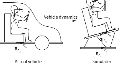
The motion simulator or the motion platform will simulate such the vehicle dynamics by translating and rotating its moving-base as illustrated in Fig. 1. Fundamentally, the actual vehicle dynamics involve both translational accelerations in all three directions and angular rates about three principle axes. The motion platform replicates the accelerations by creating translation and tilt motions while the angular rates are reproduced by rotation. Depending on purposes, the motion platform configurations vary from one to six degree-of-freedom (DOF). A 6 DOF motion platform can move in three translational degrees of freedom (surge, sway, heave) and three rotational degrees of freedom (roll, pitch, yaw).
Fig. 1. Simulation of actual vehicle dynamics on motion platform.
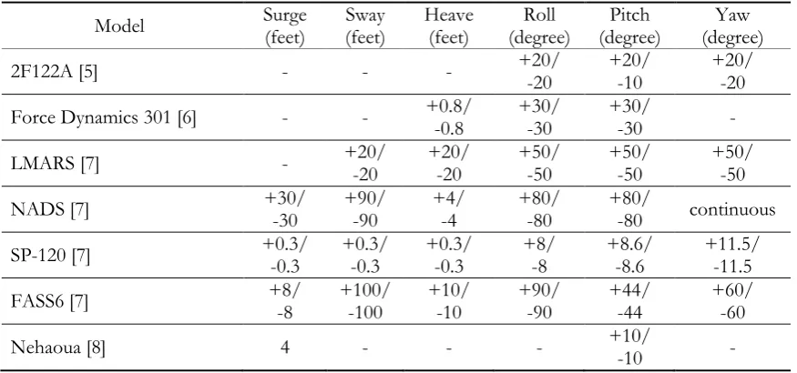
The capability of the motion platform depends on the platform architecture and type of simulated maneuverers. It can be classified by the degrees of freedom or by applications such as flight simulator, driving simulator, racing game and theatre system. Table 1 shows the degrees of freedom and the workspace of some simulators [5-8].
Due to the limitations of the workspace, the motion platform cannot simulate a continuously long data set of vehicle dynamics of the actual vehicle. Namely, replicating the exact vehicle dynamics can causes the motion platform to crush its boundaries. To solve this problem, a logic referred as a washout filter is applied. Washout filter is functioned to reproduce the actual vehicle dynamics by limiting motions and wash out to platform’s neutral position. Generally, washout filter applied in several researches are classical, adaptive and optimal washout filters.
[image:2.595.199.407.368.483.2]between vehicle sensation and simulator sensation [10, 11, 23]. In the last several years, the interest in the optimal washout filter has spread exponentially for several researches in order to improve calculation technique for the realistic motion cues [15, 24-26]. However, none of researches shows that human perception can be directly evaluated by their motion cues. As a result, this work focuses on the improvement of new motion control corresponding to the real human sensation.
Table 1. Configuration Workspace of Simulators.
Model Surge (feet) (feet) Sway Heave (feet) (degree) Roll (degree) Pitch (degree) Yaw
2F122A [5] - - - +20/ -20 +20/ -10 +20/ -20
Force Dynamics 301 [6] - - +0.8/ -0.8 +30/ -30 +30/ -30 - LMARS [7] - +20/ -20 +20/ -20 +50/ -50 +50/ -50 +50/ -50 NADS [7] +30/ -30 +90/ -90 +4/ -4 +80/ -80 +80/ -80 continuous SP-120 [7] +0.3/ -0.3 +0.3/ -0.3 +0.3/ -0.3 +8/ -8 +8.6/ -8.6 +11.5/ -11.5 FASS6 [7] +8/ -8 +100/ -100 +10/ -10 +90/ -90 +44/ -44 +60/ -60
Nehaoua [8] 4 - - - +10/ -10 -
In this research, we propose a novel approach to realistically create human-motion-sensation control based on human Central Nervous System (CNS) model. CNS is a nervous system that enables human to perceive motions using information from vision, tactile, proprioceptive and vestibular system. When human subjects to motions, CNS responses by sending a signal such as vestibulo-ocular reflex (VOR) to control eye muscle to move in the opposite direction thus stabilizing human’s gaze on a focus point. We then can evaluate human motion sensation by comparing VOR measured from human and VOR calculated from CNS model. The rest of the paper is managed as following sections. Section 2 reviews traditional washout controls for motion simulators. Details of the central nervous system are further described in Section 3. Section 4 proposes the CNS-based motion control. Section 5 compares simulation results from CNS-based motion control and other washout filters. To verify CNS-based motion control, we performed subjects experiment on Force Dynamics 301 simulator and measured the human motion sensation thru vestibulo-ocular reflex (VOR) by EyeSeeCam vHit camera device. Details are explained in Section 6. Finally, conclusion is presented in the last Section.
2.
Traditional Controls for Motion Simulators
2.1. Classical Washout Filter
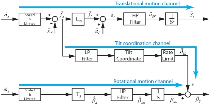
Classical washout filter applies linear high-pass and low-pass filters for replicating the actual vehicle dynamics as shown in Fig. 2. The imitation has begun with linear accelerationvector ( ) and angular rate vector ( ). Both inputs are scaled, limited and filtered to restrict to the physical movement of simulator. The algorithm is divided into translational motion channel, tilt coordination channel and rotational motion channel.
A
[image:3.595.80.518.190.395.2]Fig. 2. Classical washout filter algorithm. 2.1.1. Translational motion channel
Human cannot directly perceive the linear acceleration rather than the difference between the linear acceleration and the gravitational acceleration so called specific force as
A A A
f a g (1)
Refer to Fig. 2, the specific forces ( f ) are calculated by multiplying the specific forces (I f ) by A
transformation matrix ( L ). Then the accelerations (IS aI ) are obtained by adding the gravitational
accelerations (gI) into the specific forces ( f ). The resulting accelerations (I aI ) are passed through the
second order high-pass filters (HPTR) to maintain the motion in the workspace as Eq. (2) resulting in
high-pass acceleration signals (aIH). Then, the filtered signals are integrated twice to generate the translational
position vector (S ) for platform’s actuators. I
2
2 2
2 TR
n n
s HP
s s (2)
where, s is Laplace transform,
is damping ratio,
nis natural frequency. Here, ( )I is referred to initial reference frame and ( )A is referred to vehicle reference frame.2.1.2. Tilt coordination channel
The sustained accelerations causing the simulator reaches the boundary limitation can be replicated by tilting the platform instead. The low-pass specific force signals ( fAL) are derived from passing the specific forces
( f ) through low-pass filers (A LP ) in Eq. (3). Euler angular positions (SL ) can be calculated by tilt
coordinateas shown in Eq. (4).
2
2 2
2 n
n n
LP
s s (3)
1
tan AL
SL
f
[image:4.595.127.482.78.258.2]2.1.3. Rotational motion channel
Rotational channel copes with the angular rate vector of the actual vehicle. The Euler angular rates (A) can
be obtained by multiplying angular rates (
A) by transformation matrix (T ). The resulting signals are then Spassed through the first order high-pass filters (HPRO) as Eq. (5). Then, the output signals are integrated to
offer the Euler angular positions. The total Euler angular vector at simulator reference frame (S) for the
simulator are computed from Eq. (6).
RO
n
s HP
s (5)
S SLSH (6)
2.2. Adaptive Washout Filter
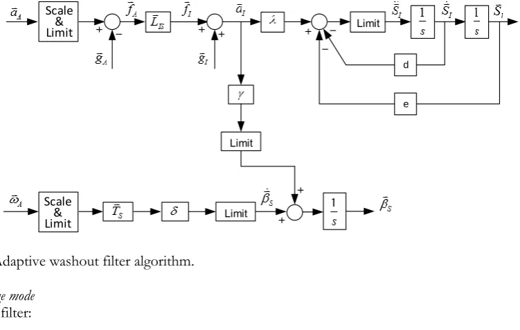
Adaptive washout filter was firstly developed by Parrish [19] at NASA Langley Research Center. The intent of the algorithm is to make full use of the simulator movement all the time by adjusting the filter parameters to the current state of the motion. As shown in Fig. 3, three adjustable gains for translation, tilt and rotation are , and , respectively. These gains are chosen to minimize the costing function between the vehicle dynamics and motion platform dynamics. Two fixed parameters are d and e. Similar to classical washout filter, linear accelerations and angular rates are the algorithm inputs. The adaptive gains can be derived as following
Fig. 3. Adaptive washout filter algorithm. Pitch/Surge mode
Adaptive filter:
x x x x
I x I x I x I
S a d S e S (7)
( x)
S LIM x If x A (8)
where,
is pitch angle, ( )S is referred to simulator reference frame, ( )A is referred to vehicle reference frame, ( )xI is referred to x-direction of initial reference frame and ( )x is referred to constant parameters in x-direction.
Limit
Limit
d
e
Limit
[image:5.595.109.485.404.642.2]Define the cost function
2 2 2 2 2 2
1 2 3 4 5
2 2 2
6 7 8
0.5{( ) ( ) [ ( ) ( ) ]
( ) ( ) ( ) }
x x x x
x I I x A S x x I x I x S x S
x x x x x x
J a s W W S W S W W
W P W P W P (9)
where, Wii are weighting parameters and Pi are initial value parameters for all adaptive filter equations.
The steepest descents for the adaptive gains are:
x x x x J G (10) x x x x J G (11) x x x x J G (12)
where, Giiare constants for all adaptive filter equations.
Roll/Sway mode
The adaptive filter, cost function and steepest descent are in the same pattern as described in pitch/surge mode. The coordinates are changed from substitution of y for x and
for
(
is roll angle).Yaw mode
Adaptive filter:
S z Ak 1
Sdt k 2
S (13)where, kiiare fixed parameters for all adaptive filter equation. is yaw angle.
Define the cost function
0.5[(AS)2( 1S2 2S2) 3( ) ]2
J W W W P (14)
The steepest descents for the adaptive gains are:
J G (15) Heave mode Adaptive filter:
1
2 3Z x z z z
I z I z I z I z I
S a k S dt k S k S (16)
2 2 2 2
1 2 3
0.5{( z z) [ ( )z ( ) ]z ( ) }
z I I z z I z I z z z
J a s W S W S W P (17)
The steepest descents for the adaptive gains are:
z
z z
z
J
G (18)
2.3. Optimal Washout Filter
Optimal washout filter employs the linear quadratic optimal control as a tracking problem. It is aimed to minimize the error between actual driver sensation and simulator driver sensation which is assumed to be identical to the simulator motion as shown in Fig. 4. The optimal washout filter for translational, tilt and rotation channel are generated by off-line computation. The linear filter matrix relates to the actual motion sensation state and simulator motion sensation states to require . The matrix cells of washout filter ( ) for translation, tilt and rotation are described in Fig. 5.
Fig. 4. Optimal washout filter algorithm.
Fig. 5. Optimal washout filter model with translational, tilt and rotational filters.
Known as human motion sensation organ, vestibular system is the visual sensing organ in the non-auditory section on both sides of the inner ears. The vestibular system composes of semicircular canals and otoliths responding to the motion from angular rate and linear acceleration, respectively. The mathematical model of semicircular canals and otoliths are represented in Eq. (19) and (20) [27].
2 1
1 2
ˆ
( ) (1 )
(1 )(1 )(1 )
( )
scc a L
a
s G s s
s s s
s (19)
(s)
S A
u W u
(s)
[image:7.595.160.437.315.594.2]
0 1 0
ˆ( ) K ( )
( ) ( )( )
OTO OTO
f s G s A
f s s B s B (20)
where, GSCCand iare semicircular canal model parameters and time constants, GOTO, KOTO,A0,B0and 1
B are computed otolith model parameters.
The details for formulating the optimal washout filter are as followings. The state-space formulation of the vestibular system can be obtained by giving the vehicle inputs as
A u f
Equations (19) and (20) can be rearranged into vestibular system state-space form as
A V A V A
x A x B u (21)
A V A V A
y C x D u (22)
where, AV is vestibular system matrix,BV is input matrix,CVis state observation matrix andDVis control
observation matrix. 0 , , 0 SCC SCC V V OTO OTO A B A B A B 0 , 0 SCC SCC V V OTO OTO C D C D C D
The errors of vestibular state and driver’s sensation state are defined as xexSxA ande yS yA .
Substituting these error into Eq. (21) and (22) yields
e V e V S V A
x A x B u B u (23)
V e V S V A
e C x D u D u (24)
The additional motion state variable to constrain the simulator motion for explicit access state as linear velocity and displacement is
d d d d S
x A x B u (25)
Filter white noise is applied as input to cover many input manoeuvres which are represented as
n n n n
x A x B w (26)
A n
u x (27)
where,
1and
2 are constants.Grouping Eq. (23)-(27) to state-space form results
s
x Ax Bu Hw (28)
s
y Cx Du (29)
where,
[ ] ,T [ ]T
e d n d
x x x x y e y
0 0
0 0 , , 0
0 0 0
V V V
V d
n n
A B B
A A B B H
A B 0 ,
0 0 0
V V V
C D D
C D
I
Define the costing function
0 ( )
t
T T T
d d d S S
J E e Qe x R x u Ru dt (30)
The costing function can be calculated by Hamiltonian equation. The costing function in Eq. (30) is minimize by selecting
1
2 [ 12]
T T
S
u R B P R x (31)
S
u Kx (32)
where, R2 R D GD , T
12 T
R C GD .
Solving P by Riccati equation and partition the resulting equation yield
1 1 1
[ ]
e
S d
n
x
u K K K x
x
(33)
Substituting Eq. (27) into Eq. (33) yields
1 1 1
[ ]
e
S d
A
x
u K K K x
u
(34)
0 0 0 e
e V V V
d S
d d d
A
x
x A B B
x u
x A B
u
(35)
and substituting Eq. (34) into Eq. (35) yields in
1 2 3
1 2 3
( )
e V V V e V
A
d d d d d d
x A B K B K x B I K
u
x B K A B K x B K (36)
Solving [ ]T
e d
x x of Eq. (36) results in Laplace transform and substituting [ ]T
e d
x x into Eq. (34) yields
11 2 3
1 2 3
1 2 3
( )
( ) V V V V A
d d d d
sI A B K B K B I K
u s K K K u
B K sI A B K B K (37)
Therefore, washout filters can be summarized as
11 12 21 22 ( ) ( ) ( ) ( ) ( )
W s W s
W s
W s W s (38)
3.
Central Nervous System (CNS)
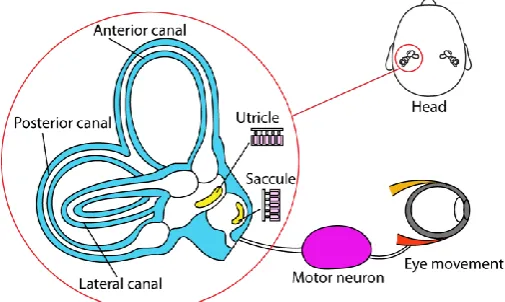
Daily activities of human being involve human’s body orientation, postural control (balance) and movement. Human can manage these activities by the non-visual sensing organ in the non-auditory section of the inner ear which is called vestibular system. The vestibular system is on both sides of human’s inner ears. It is an initial measuring unit responding to body balancing and stabilized gazing on a point in space. The vestibular system is composed of two sensing organs including semicircular canal and otolith. Three semicircular canals detect three rotational movements including anterior, posterior and lateral canals which are mutually orthogonal planes. Two otolith sensors (utricle and saccule) are nearly perpendicular with each other. Otolith senses to three linear acceleration and static tilt of human head relative to gravity.
Fig. 6. Vestibular system and eye moment.
[image:10.595.171.424.508.659.2]8, once the head turns right, nervous signals from semicircular canals are transmitted to eye muscles to move the eyes to the left
(a) (b) (c) Fig. 7. Response of otolith from head movement.
Fig. 8. Eye movement during head turn right.
For highly complex movements and orientations of the vehicles, human cannot rely only on vestibular system to sense the true perception of the highly dynamic motions. Thus, vision, audition, touch and proprioception inputs also come to play.
Central nervous system (CNS) is the part of nervous system integrating and coordinating the activities of the entire body. CNS will receive information (deterministic stimuli) from such a variety of sources as vision, sound, tactile, proprioceptive and also vestibular system. Then, CNS performs a proper response to the stimuli by means of peripheral sensory organs including eyes, muscles and joints.
Many researches attempt to develop CNS model to simulate the human perception. Borah [28] purposed the multisensory motion perception model to represent the neural central processing as shown in Fig. 9. The model applied an optimal estimation technique to integrate multiple sensory inputs. Multisensory spatial orientation was studied for motion perception [29]. Merfeld [30, 31] studied sensory conflict information between body dynamics and sensory dynamics as shown in Fig. 10. The block diagram for CNS model is shown in Fig. 11. The system inputs are three angular velocities and three linear accelerations. The outputs of CNS model compose of three dimension estimation of acceleration, gravity, angular velocity and VOR responding to body movements.
[image:11.595.173.408.120.372.2] [image:11.595.198.409.127.230.2] [image:11.595.156.442.592.727.2]Fig. 10. Sensory Conflict Model [30].
From Fig. 11, angular velocity vector is passed through the reduced order semicircular canal model as described in Eq. (39) to generate the semicircular canal signal(SCC).
2 ( )
( ) ( 1/ )( 1/ )
SCC
d a
s s
s s s (39)
where, d and a are time constant.
The gravity which is affected from the orientation is represented by a differential equationds dt/ g. The gravito-inertial force can be calculated by subtracting the acceleration vector from gravity vector. The gravity is passed through the graviceptor model as proportional to gravitational force (a unit in Laplace transform) to provide the otolith signal(OTO). The internal model also generates the predicted semicircular
canal and otolith signals but the dynamic model of semicircular canal is changed as in Eq. (40).
ˆ ( )
ˆ( ) ( 1/ )ˆ
SCC
d
s s
s
s (40)
where, ˆd is time constant.
The internal model of graviceptor is the same as those for physical model. The error between three physical signals and three predicted signals are multiply by four feedback gains to get the internal model inputs. These gains are obtained by trial and error. The outputs of sensory model are the estimated angular velocity vector , estimated acceleration vector and estimated gravity vector . The estimated signals are processed to gain the VOR as depicted in Fig. 11. The angular VOR is the negatively estimated of angular velocity. To generate translation VOR, the estimated acceleration is converted to velocity with time constant of 0.1 sec. After that, the resulted velocity is cross product with the estimated target proximity . The VOR is the combination of angular VOR and translation VOR. The parameters of this work are shown in Table 2.
ˆ
( ) ( )aˆ ( )gˆ
ˆ ˆ
Fig. 11. Central nervous system [31]. Table 2. CNS parameters [31].
Model feedback parameters
k 3
a
k -2
f
k 2
f
k 2
Semicircular canal parameters
d
ˆd 5
a 80ˆd 1
4.
CNS-based Motion Control
Driving in the real situation, the driver must encounter with several stimuli such as vision, sound, touch, acceleration and angular rate. As mentioned in Section 3, CNS model can simulate the human perception including the estimated acceleration, the estimated angular velocity, the estimated gravitation and the estimated VOR. Therefore, designing the motion platform relative to the estimated perception will make use of the appropriate motion platform corresponding to realistic motion.
[image:13.595.190.403.442.614.2]of the acceleration, angular rate and gravitations from CNS model are used as input for adaptive washout filter. Finally, the translational and Euler angular positions for controlling the simulator are produced.
Fig. 12. CNS-based motion control.
5.
Comparison of Washout Algorithms
In this section, computer simulation was used to generate the motion cues for classical, adaptive, optimal and CNS-based motion control filters by MatLAB/Simulink. For illustrative purpose, this work selected the washout filter parameters as in Table 3. Table 4 collected the optimal washout filter parameters referred from Young and Meiry model [27]. CNS parameters referred from Table 2. Here we consider simulating a high acceleration of a supercar. The longitudinal acceleration of 4 m/s2 step input is shown in Fig. 13. This section compares simulation responses from all wash out filters and CNS-based motion control.
The simulation results are shown in Fig. 14. The corresponding comparison of translational and angular positions is plotted in Fig. 14. Figure 14(a) displays the translational positions in meters for surge, sway and heave against time in seconds. The roll, pitch and yaw angular positions in degrees versus time in seconds are displayed in Fig. 14(b). The workspaces requiring for each type of filters are concluded in Table 5.
For longitudinal acceleration, the algorithms create motion positions for surge, heave and pitch. The simulations showed that CNS-based motion control can significantly decrease surge motion to 0.07 m. Translating in heave direction was reduced to 0.39 m. Note that motion is smoother than those of optimal washout filter. Furthermore, it could be seen that CNS-based motion control can also depress the hard motion cues from adaptive washout filter.
Reducing of translation positions was possibly effected from the physical property of semicircular canal and otolith. Semicircular canal would response at low frequencies but otolith reacted at high frequencies [32]. Therefore, CNS-based motion control enables realistic perception with shorter range motions which lead to more usable simulator workspace.
Fig. 13. Longitudinal acceleration step input of 4 m/s2.
0 5 10 15 20 25 30
0 1 2 3 4 5
Time (sec.)
L
o
n
g
itu
d
in
a
l A
c
c.
(
m
/s
[image:14.595.218.372.595.718.2] n (rad/s)
Classical washout filter - 2nd HP filter - 2nd LP filter - 1st HP filter
0.75 0.75 -
1 1 1 Adaptive washout filter
- 2nd HP filter - 2nd LP filter - 1st HP filter
0.75 0.75 -
1 1 1
CNS-Based motion control - 2nd HP filter
- 2nd LP filter - 1st HP filter
0.75 0.75 -
1 1 1
Table 4. Optimal washout filter parameters [27].
Semicircular canal model parameters
Parameters Pitch/Surge Roll/Sway Yaw Heave
Threshold 2 2 1.6
1 5.37 5.73 5.73
2 0.005 0.005 0.05
a 80 80 80
L 0.06 0.06 0.06SCC
G 28.6479 28.6479 35.8099
Otolith canal model parameters
Parameters Pitch/Surge Roll/Sway Yaw Heave
Threshold 0.17 0.17 0.28
0
A 0.1 0.1 0.1
0
B 0.2 0.2 0.2
1
B 62.5 62.5
OTO
G 4.71*B1 4.71*B1 2.8571
[image:15.595.159.438.103.296.2] [image:15.595.152.442.338.570.2]Fig. 14. Comparison of simulation positions (a) surge, sway, heave and (b) roll, pitch, yaw. Table 5. Workspace form acceleration of 4 m/s2.
Algorithm Surge (m) Sway (m) Heave (m) (degree) Roll (degree) Pitch (degree) Yaw Classical +2.10 -2.10 - +0.20
-0.81 -
+24.4
-1.00 -
Adaptive +0.18 -0.18 - +0.03
-0.82 -
+22.2
[image:16.595.128.467.678.764.2]Optimal +1.20 -1.20 - +0.35
-0.39 -
+13.0
-2.02 -
CNS-based Control
+0.07
-0.07 -
+0.02
-0.39 -
+22.5
-0.21 -
6.
Experiment
When human head is moved, the vestibular system will send the information, rotation and linear motion, to CNS. Then, CNS will integrate the information to produce motor command to eye muscles in order to control eye movement to stabilize the line of sight called vestibulo-ocular reflex (VOR). VOR has a function to maintain the best vision by moving the eyes during head movement. Normally, the eye motion will equal and opposite to the head motion. As a result, this work will introduce VOR measurement to evaluate the human motion perception.
[image:17.595.129.466.79.142.2]We set up experiments using Force Dynamics 301 simulator platform. For safety reasons, a ramp acceleration profile of 2 m/s2 shown in Fig. 15 was used as an input. The parameters and gains were referred from Table 2, Table 3 and Table 4. All washout filters including CNS-based motion control were implemented to generate motions accordingly. Here subjects are equipped with a EyeSeeCam vHit camera to measure their VORs.
Fig. 15. Longitudinal acceleration ramp-step-ramp input of 2 m/s2.
[image:17.595.193.393.336.498.2]Figure 16 presents the Flow chart of the experiment. The motion positions generated from each of all washout filters were sent to Force Dynamics 301 simulator (3 DOF for heave, roll, and pitch) to perform simulator test. Subjects were seat securely on the simulator. The system measured VOR by EyeSeeCam vHit (commercial medical grade camera). The measured VORs from all driving cases were compared to the estimated VOR from CNS model.
Fig. 16. Flow chart of simulator driving and VOR measurement.
0 2 4 6 8 10 12
0 0.5 1 1.5 2 2.5 3
Time (sec.)
L
o
n
g
it
u
d
in
a
l
A
c
c
. (
m
/s
[image:17.595.159.433.612.724.2]Fig. 17. Force Dynamics 301 simulator.
Fig. 18. EyeSeeCam vHit.
Many works employed number of subjects around 5-10 persons for vetibulo-ocular reflex experiment [33-37]. For this work, six subjects with no previously history of central vestibular disorders were participated for four passive driving tests. Six healthy subjects include 3 men and 3 women (age between 22 and 38). All subjects were trained for the driving experiment to prevent the bias results [36]. Each subject was comfortably seated in the simulator cockpit and pointing straight ahead at a fix point on a screen placed 1 m in front. The resulted responses for all washout filters are shown in Fig. 19.
Due to the limitation of simulator’s degrees of freedom, this work used 3 DOF (heave motion, roll and pitch angular motion) for driving test. The comparisons between the average of measured and estimated VORs in degrees/seconds against time in seconds are displayed in Fig. 20. Table 6 shows the maximum values for both measured and estimated VORs
Fig. 20. VOR comparison between measurement and estimation. Table 6. Maximum value of measured and estimated VOR.
Estimated
VOR Measured VOR
Classical
filter Adaptive filter Optimal filter based CNS-control VOR
( / sec)
+46.85 -66.81
+25.03 -32.08
+51.32 -53.55
+34.89 -34.81
+43.09 -53.70
7.
Conclusion
Motion simulator plays a significant role for replicating the actual dynamics of vehicle. This paper addresses motion control approaches for driving simulators that implement various washout filters covering classical, adaptive, and optimum filters. These controls exhibited some realism limitation and requiring of large workspace to implement.
To date, achievement of realistic motion control has impacted to human sensation. Here we proposed a novel CNS-based motion control algorithm that realistically creates motion perception for human on motion simulators with effective workspace. From longitudinal acceleration simulation test, CNS-based motion control decreased surge motion up to 97.67%, 61.11% and 94.17% compared to classical, adaptive and optimal washout filter, respectively. On heave motion, CNS-based motion control required distance equal to optimal washout filter but reduced distance up to 51.19% and 52.44% compared to classical and adaptive washout filters, accordingly.
Based on VOR experiment, the errors between measured VOR of classical, adaptive, optimal, based motion and estimated VOR are 46.57%, 9.54%, 23.71% and 8.03%, respectively. Therefore, CNS-based motion control provided better realistic human motion perception as it has less error between measured and estimated VORs while adaptive, optimal and classical washout filters generate hard, medium and soft
0 5 10 15 20
-80 -60 -40 -20 0 20 40 60
Time (sec.)
V
O
R
(d
e
g
re
e
/s
e
c
)
Measured VOR (Classical) Measured VOR (Adaptive) Measured VOR (Optimal)
[image:20.595.154.443.430.527.2]translation positions.
Current findings lead to the conclusion that CNS-based motion control is a superior algorithm of generating realistic motion control than the motion controls from the conventional algorithms. Further investigation can be extended to 6 DOF motion platform with several driving scenarios.
References
[1] R. Chaichaowarat and W. Wannasuphoprasit, “Dynamics and simulation of RWD vehicle drifting at steady state using BNP-MNC tire model,” SAE-International Journal of Transportation Safety, vol.1, no.1, pp. 134-144, 2013.
[2] R. Chaichaowarat and W. Wannasuphoprasit, “Optimal control for steady state drifting of RWD vehicle,” in Proceedings of the 7th IFAC Symposium on Advances in Automotive Control (IFAC-AAC’ 2013), Tokyo, Japan, 2013, pp. 814-820.
[3] S. Chantranuwathana, R. Chancharoen, W. Wannasuphoprasit, A. Sripakagorn and N. Noomwons, “Tire-suspension-steering hardware-in-the-loop simulation,” Engineering Journal, vol. 22, no. 5, pp. 199-212, 2018.
[4] R. Chaichaowarat and W. Wannasuphoprasit, “Kinematics-based analytical solution for wheel slip angle estimation of a RWD vehicle with drift,” Engineering Journal, vol. 20, no. 2, pp. 89-107, 2016.
[5] C. J. Gutridge, “Three degree-of-freedom simulator motion cueing using classical washout filters and acceleration feedback, Aerospace Engineering,” Virginia Polytechnic Institute & State University, 2004. [6] Force Dynamics. (2014). Force Dynamics Quick Info Sheet [Online]. Available:
https://www.force-dynamics.com/presskit/forcedynamics-quickinfo-october14.pdf [Accessed: May 28, 2018].
[7] C. S. Liao, C. F. Huang, and W. H. Chieng, “A novel washout filter design for a six degree-of-freedom motion simulator,” JSME International Journal Series C Mechanical Systems, Machine Elements and Manufacturing, vol. 47, pp. 626-636, 2004.
[8] L. Nehaoua, H. Mohellebi, A. Amouri, H. Arioui, S. Espié, and A. Kheddar, “Design and control of a small-clearance driving simulator,” IEEE Transactions on Vehicular Technology, vol. 57, no. 2, pp. 736-746, 2008.
[9] S. F. Schmidt, and B. Conrad, “Motion drive signals for piloted flight simulators,” NASA CR-1601, 1970.
[10] L. D. Reid, and M. A. Nahon, “Flight simulation motion-base drive algorithms Part I Developing and testing the equations,” Institute for Aerospace Studies, University of Toronto, 1985.
[11] L. D. Reid and M. A. Nahon, “Flight simulation motion-base drive algorithms: Part II Selecting the System Parameters,” Institute for Aerospace Studies, University of Toronto, 1986.
[12] L. Nehaoua, H. Arioui, S. Espie, and H. Mohellebi, “Motion cueing algorithms for small driving simulator,” in IEEE International Conference on Robotics and Automation, 2006, pp. 3189-3194.
[13] B. Wu, X. Yu, J. Li, and G. Han, “Design of intelligent washout filtering algorithm for water and land tank mMotion simulation,” International Conference on Intelligent Human-Machine Systems and Cybernetics, vol. 2, pp. 19-22, 2009.
[14] M. S. Kim, Y. G. Moon, G. D. Kim, and M. C. Lee, “Partial range scaling method based washout algorithm for a vehicle driving simulator and its evaluation,” International Journal of Automotive Technology, vol. 11, no. 2, pp. 269-275, 2010.
[15] S. H. Chen, and L. C. Fu. “An optimal washout filter design for a motion platform with senseless and angular scaling maneuvers,” in Proceedings of the 2010 American Control Conference, 2010, pp. 4295-4300. [16] S. Casas, and I. Coma, J. V. Riera, and M. Fernandez, “Motion-cuing algorithms: characterization of
users’ perception,” Human Factors, vol. 57, no. 1, pp. 144-162, 2014.
[17] W. Jiang, and H. Fajiang, “Development and implementation of a washout algorithm for a 6-dof motion platform of flight simulator,” International Journal of Research in Engineering and Science, vol. 13, no. 7, pp. 08-14, 2015.
[18] B. Volkaner, S. N. Sozen, and V. E. Omurlu, “Realization of a desktop flight simulation system for motion-cueing studies,” International Journal of Advanced Robotic Systems, vol. 13, no. 3, pp. 1-14, 2016. [19] R. V. Parrish, J. E. Dieudonne, R. L. Bowles, and D. J. Martin, Jr., “Coordinated adaptive washout for
[20] F. Colombet, M. Dagdelen, G. Reymond, C. Pere, F. Merienne, and A. Kemendy, “Motion cueing: What’s the impact on the driver’s behaviour?,” Driving Simulator Conference, pp. 171-181, 2008.
[21] N. J. I. Garrett and M. C. Best, “Driving simulator motion cueing algorithms—A survey of the state of the art,” in Proceedings of the 10th International Symposium on Advanced Vehicle Control, 2010, pp. 183-188. [22] C. Huang, “Adaptive washout filter design with human visual-vestibular based (HVVB) for VR-based
motion simulator,” in The 2010 International Joint Conference on Neural Networks (IJCNN), 2010, pp. 1-6. [23] R. Sivan, J. Ish-Shalom, and J. K. Huang, “An optimal control approach to the design of moving flight
simulators,” IEEE Transactions on Systems, Man, and Cybernetics, vol. 12, no. 6, pp. 818-827, 1982.
[24] J. B. Song, U. J. Jung, and H. D. Ko, “Washout algorithm with fuzzy-based tuning for a motion simulator,” KSME International Journal, vol. 17, no. 2, pp. 221-229, 2003.
[25] T. S. Hwang, M. S. Kuo, and S. P. Hsieh, “Optimal genetic and adaptive fuzzy washout filter design in the motion‐ cueing simulator,” Asian Journal of Control, vol. 10, no. 1, pp. 88-95, 2008.
[26] H. Asadi, S. Mohamed, K. Nelson, S. Nahavandi, and M. Oladazimi, “An optimal washout filter based on genetic algorithm compensators for improving simulator driver perception,” in Proceedings of the Driving Simulation Conference & Exhibition, 2015, pp. 1-10.
[27] R. J. Telban and F. M. Cordullo, “Motion cueing algorithm development: Human-centered linear and nonlinear approaches,” NASA/CR-2005-213747, 2005.
[28] J. Borah, L. R. Young, and R. E. Curry, “Optimal estimator model for human spatial orientationa,” Annals of the New York Academy of Sciences, pp. 51-73, 1988.
[29] L. R. Young, “Perception of the body in space: mechanisms (Reprint),” Comprehensive Physiology, pp. 1023-1066, 2011.
[30] D. M. Merfeld, “A multidimensional model of the effect of gravity on the spatial orientation of the monkey,” Journal of Vestibular Research, vol. 3, pp, 141-61, 1993.
[31] D. M. Merfeld and L. H. Zupan, “Neural processing of gravitoinertial cues in humans. III. modeling tilt and translation responses,” Journal of Neurophysiology, vol. 87, no. 2, pp. 819-833, 2002.
[32] L .H. Zupan, S. Park, and D. M. Merfeld. “The nervous system uses internal models to achieve sensory integration,” in The 26th Annual International Conference of the IEEE Engineering in Medicine and Biology Society, 2004, pp. 4487-4490.
[33] J. L. Meiry, “The vestibular system and human dynamic space orientation,” Ph.D. Thesis, Aeronautics and Astronautics, Massachusetts Institute of Technology, 1965.
[34] L .H. Zupan, R. J. Peterka, and D. M. Merfeld, “Neural processing of gravito-inertial cues in humans. I. influence of the semicircular canals following post-rotatory tilt,” Journal of Neurophysiology, vol. 84, no. 4, pp. 2001-2015, 2000.
[35] L. H. Zupan and D. M. Merfeld, “Human ocular torsion and perceived roll responses to linear acceleration,” Journal of Vestibular Research, vol. 15, no. 4, pp. 173-183, 2005.

![Fig. 9. Multisensory model [28].](https://thumb-us.123doks.com/thumbv2/123dok_us/8106467.235247/11.595.173.408.120.372/fig-multisensory-model.webp)
![Fig. 10. Sensory Conflict Model [30].](https://thumb-us.123doks.com/thumbv2/123dok_us/8106467.235247/12.595.158.450.75.286/fig-sensory-conflict-model.webp)
![Table 2. CNS parameters [31].](https://thumb-us.123doks.com/thumbv2/123dok_us/8106467.235247/13.595.133.453.82.390/table-cns-parameters.webp)

