Article
Design of Hip Simulation Machine for Hip Labrum
Testing
Chanatkarn Angsutanasombat
1,a, Panya Aroonjarattham
1,b, Nadhaporn Saengpetch
2,c,*,
Pornsak Nirunsuk
2,d, Kitti Aroonjarattham
3,e, and Chompunut Somtua
1,f1 Department of Mechanical Engineering, Faculty of Engineering, Mahidol University, Nakornpathom,
Thailand
2 Department of Orthopaedics, Faculty of Ramathibodi Hospital, Mahidol University, Bangkok, Thailand 3 Department of Orthopaedics, Faculty of Medicine, Burapha University, Chonburi, Thailand
E-mail: a[email protected], b[email protected], c[email protected] (Corresponding author), d[email protected], e[email protected], f[email protected]
Abstract. The acetabular labrum is the connective tissue between femoral head and hip joint that acts like a shock absorber. Labral injury could happen after hip dislocation or internal derangement such as femeroacetabular impingement (FAI) syndrome. The surgeon usually attempts to repair or reconstruct the torn labrum to obtain the native hip biomechanical loading. There has been no scientific evidence study for the different surgical techniques. Hip simulation machine was made to let a femur move in six conditions including flexion, extension, abduction, adduction, internal rotation and external rotation. The hip was compressed with a force of half of the body weight (350 N). The purpose of this study was to study pressurization in three labral conditions including intact labrum, labral repair and labral reconstruction. The machine was designed and simulated by SolidWorks software. A device’s controller had two mode including a manual mode to set zero before an operation and automation mode to move in six conditions and compressed with a force of body weight. After the construction, the machine was tasted by using counterfeit pelvis and femur. The device was reformed before a real taste. Dissected cadaveric pelvises were used and measured pressure through the film piezoresistive load sensors. The testing result was helped the surgeon to make a decision in surgery process.
1.
Introduction
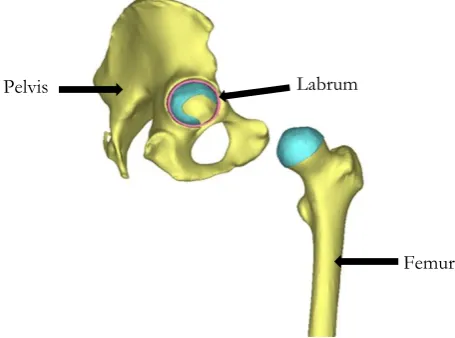
Labrum is fibrous thickening rims of cartilage surrounding the socket of hip joint as shown in Fig. 1 that protects the joint surface, stabilize the hip socket by keep the femoral head inside the acetabulum [1,2] and distribute the loads and pressures of the articular surface [3, 4, 5]. The injury of labrum tends to chronical hip pain [6, 7, 8]. Hip pain and disability could occur from the acetabular labral tears after hip dislocation or internal derangement [9, 10, 11]. The acetabular labrum tears had 75% of an unknown cause and 25% were occurred by accident, excessive force, hip dislocation, hip degeneration, capsular hip hypermobility, and hip dysplasia [12].
Fig. 1. The component of hip joint and position of labrum.
The occurrenceof labral tears has increased with ages that caused by aging process and were thought to be from gradual tear due to repetitive micro-trauma. Under compression force of body weight in a neutral hip condition, the acetabular labrum resists the femoral head dislocation despite being detached from the acetabular rim. When the labral tear occurred, the hip stability decreased [5, 13, 14, 15, 16]. Treatment of labral tears depend on the severity of the symptoms and the specific characteristics of the tear and the surgical operation may be solved with either repair of the labral tissue using suture or using a local tendon to reconstruct the irreparable labrum depends on the type of tear and tears’ characteristics.
This research aimed to develop a hip simulation machine and tested how the labral tear affect the pressure in the hip joint by compared the intact labrum with labral repair and labral reconstruction. The machine was designed to mimic a real human’s hip movement as abduction, adduction, flexion, extension, internal rotation and external rotation under constant body weight. The pressure sensor was used to measure in the hip socket to compare between intact labrum, labral repair and labral reconstruction conditions.
2.
Materials and Methods
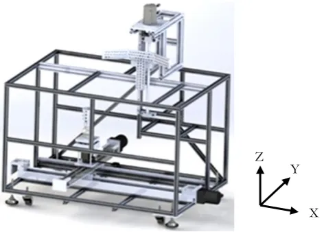
Hip simulation machine was created by SolidWorks CAD software (Version 2010; Mahidol University; Nakhon Pathom, Thailand) as shown in Fig. 2 to simulate the hip joint movement as adduction, abduction, flexion, extension, internal rotation and external rotation under constant body weight compression. The designed machine had dimension 1.0 x 1.2 x 1.0 meter as width x long x height.
Labrum
[image:2.595.183.411.207.376.2]Fig. 2. CAD model of hip simulation machine.
The machine was used to create the several of hip movements’ direction, which was constructed from aluminium profile by Aluminum Alloy 6063-T5 with yellow coating. The components of hip simulation machine were divided into two parts: the upper part that is used to control the force applied to the pelvis by the AC servo motor (model MSDA203A1A; Panasonic Corp.; Osaka, Japan) [17] and the bottom part which are used to control the motion of the DC motor and step motor. All of these parts are controlled by Arduino and the force applied is measured by load cells which are mounted on Z-axis as shown in Fig. 3. The maximum average weight of Thai people is 71.07 kg for men between 46-59 years [18] but the cadaver hip cannot receive that full load because the model has dissect many muscles, ligaments and tendons. During the test, in the Z-axis, AC servo motor was compressed constant force with a 0.5 times of body weight (350 N) on the vertical movement of the ball screw on the T-shape jig that used to install the testing hip.
Fig. 3. Load cell S-type to measure the load in z-axis.
The machine was moved in six directions as adduction (+X-axis), abduction (–X-axis), flexion (–Y-axis), extension (+Y-(–Y-axis), internal rotation (+Z-axis) and external rotation (–Z-axis). X- and Y-axis were moved by DC motors connected to ball screw, was controlled a position by encoders. Z-axis was rotated by a thrust ball bearing, which was controlled the ball bearing by step motor. The femur was cut at the mid-shaft region and fixed with ball bearing on the plate as shown in Fig. 4.
X Z
[image:3.595.213.451.78.247.2] [image:3.595.227.370.434.579.2]Fig. 4. Hip joint was installed in neutral position.
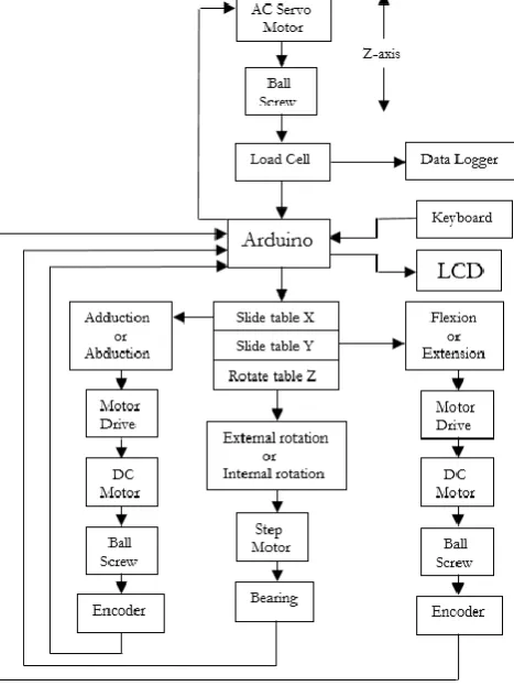
The AC servo motor can be works alternatively between the position control mode and the torque control mode. In this research, a torque control mode was used to generate the body weight force thought Z-axis by ball screw to a pelvis by controlling the constant load on the T-shape jig, using load cell to measure the force. The plate fixed the femoral shaft is placed on the X-Y slide table which moves in two directions. Flow chart of hip simulation machine to control a movement in X-, Y- and Z-axis and rotate around Z-axis was shown in Fig. 5.
Fig. 5. Flow chart of hip simulation machine.
The testing hip is held on a T-shape jig as shown in Fig. 6 with several screws which is exchangeable for different testing samples. The jig has an angle 150 degree to enclose the testing hip because the hip
X Z
[image:4.595.207.375.77.255.2] [image:4.595.190.424.382.694.2]width depends ongender, age,weight and height of human. Many slots with fillet are used to insert the screw fixing the testing hip. This experiment was divided into three testing cases:
1. Adduction or abduction, the testing hip was held on T-shape jig and compressed by AC servo motor with constant load 350 N. If the loads exceed 350 N the servo motor decrease the torque to ball screw and increase the torque when the loads lower than 350 N. The DC motor moved the slide table to +X-axis for adduction and –X-axis for abduction.
2. Flexion or extension, the testing hip was held on T-shape jig and compressed by AC servo motor with constant load 350 N. The DC motor moved the slide table to –Y-axis for flexion and +Y-axis for extension.
3. External or internal rotation, the testing hip was held on T-shape jig and compressed by AC servo motor with constant load 350 N. The step motor rotated the table around +Z-axis for internal rotation and –Z-axis for external rotation.
Fig. 6. T-shape jig for insert testing hip.
The pressure sensitivity film (K-scan sensor, Tekscan Inc., USA) was used to measure the pressure in the hip socket with the versatile I-Scan tactile pressure mapping system that measures and analyzes interface pressure between two surfaces of cartilage, utilizing a thin and flexible sensor as shown in Fig. 7. The system was comprised of data acquisition electronics, sensors, and software to measure both force and pressure. The thin tactile sensor had the minimal interference between the objects surface, allowing the true interface pressure data to be obtained.
Fig. 7. I-Scan system includes data acquisition electronics and sensor [19].
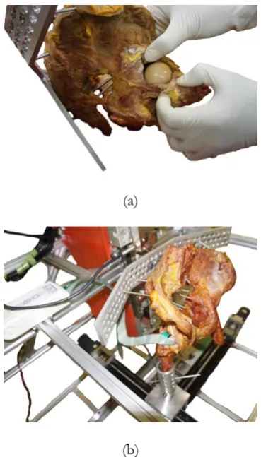
The labrum was tested under three conditions as intact labrum, labral repair and labral reconstruction. The pressure sensor was inserted in the hip socket as shown in Fig. 8.
Data Acquisition Electronics
[image:5.595.167.379.431.572.2](a)
(b)
Fig. 8. The pelvis model: (a) Opened the hip socket and (b) Inserted pressure sensor in hip socket.
3.
Result and Discussion
The result were divided into two parts as result of a hip simulation machine, was simulated under six conditions and result of pressure in hip socket under three labrum conditions.
3.1 Hip Simulation Machine
[image:6.595.205.390.76.400.2]Fig. 9. Direction of abduction and adduction from neutral alignment.
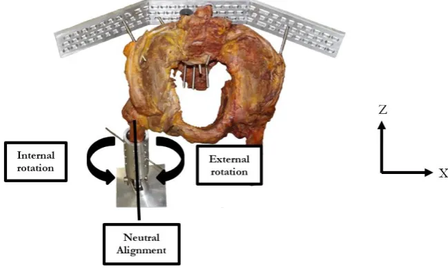
[image:7.595.99.490.78.343.2] [image:7.595.166.442.451.743.2]The internal rotation and external rotation were controlled by stepping motor around Z-axis as shown in Fig. 11. The stepping motor controlled a thrust ball bearing to rotate the rotate table Z attached the femoral shaft around +Z-axis as internal rotation with 20 degrees from neutral alignment and –Z-axis as external rotation with 20 degrees from neutral alignment as human activities [20]. The degrees of internal rotation and external rotation were counted by step motor rotating.
Fig. 11. Direction of internal rotation and external rotation from neutral alignment.
Many in vitro testing devices have been designed and used in various tests. The main purpose is to mimic the real daily activities such as the wear testing machine for dental crown application is mimic the human oral cavity condition [21], the hip joint simulator is mimic the load and angular displacements of two and three axes of hip rotation to test the wear and creep of metal-on-polyethylene bearing [22] and the mechanical simulator is mimic the cycling angular movement and loading to evaluate the hip wear performance [23, 24] and use of multi-axial wear machine [25, 26]. Hip simulation machine developed for this research applied AC servo motor to control the loading to be as close as constant body weight when the testing hip moving. Force measurement was recorded by load cells, which were placed in Z-axis and was adjusted by Arduino. The torque control mode determines the velocity of motor rotation. Thus, the velocity of the motor would affect the response of the motor; the quick rotation speed required a greater force. All testing conditions used twenty seconds for one cycle.
3.2 Pressure in Hip Socket
Fig. 12. The pressure distribute on the pressure sensor from I-Scan system.
Table 1. The maximum pressure in the hip socket under three labrum’s conditions and seven conditions of testing hip movement.
Model Side Condition of labrum Maximum pressure (kPa) Neutral Flexion Extension Abduction Adduction Internal
[image:9.595.99.499.286.683.2]Fig. 13. The average pressure in hip socket of intact labrum and labral reconstruction.
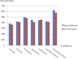
The highest average maximum pressure in hip socket occurred under external rotation condition. Labral reconstruction reduces the pressure in hip socket in all conditions except flexion and internal rotation conditions. The compared average pressure in hip socket of intact labrum and labral reconstruction under seven conditions was shown in Fig. 14.
Fig. 14. The average pressure in hip socket of intact labrum and labral repair.
[image:10.595.142.473.454.704.2]conditions. The difference of maximum average pressure in hip socket between intact versus labral reconstruction and intact versus labral repair was shown in Table. 2.
Table 2. The difference percentage of maximum average pressure in hip socket.
Condition Intact labrum and labral reconstruction The difference maximum average pressure in hip socket (%) Intact labrum and labral repair
Neutral 7.35 4.82
Flexion -7.59 2.47
Extension 11.71 3.10
Abduction 5.73 9.11
Adduction 7.49 -1.65
Internal rotation -2.83 1.83
External rotation 20.99 7.24
To consider the labral repair, the surgeon repaired the tear labrum that made the thickness reduces from the intact condition but the area increase as shown in Fig. 15. When r1 is a radius of intact labrum and
r2 is a radius of labral repair. The reduced thickness made the maximum average pressure higher than the
[image:11.595.65.533.141.245.2]intact condition because the thin labrum loss function to absorb the body weight load and femoral head placed to close the pelvis that made the bone to receive body weight without shock absorber.
Fig. 15. Top view and side view of: (a) Intact labrum and (b) Labral repair.
The labral reconstruction was used the iliotibial band that had elastic modulus 111 MPa and poison’s ratio 0.418 [28] replaced for the tear labrum that had elastic modulus 33 MPa and poison’s ratio 0.478 [30]. To consider the material properties between iliotibial band and labrum, the elastic modulus was calculated from Eq. (1).
E L L A F (1) [image:11.595.160.456.338.458.2]Fig. 16. The stress-strain curve of iliotibial band and labrum.
The surgeon should be repair the labrum when it tears because the average maximum pressure in the hip socket was occurred near the intact condition.
4.
Conclusion
The hip simulation machine was constructed, which moved under six conditions including flexion, extension, abduction, adduction, internal rotation and external rotation under constant compression load and tested the pressure in hip socket with intact labrum, labral repair and labral reconstruction. This machine could create the natural hip movement and useful for cadaveric laboratory testing in different surgical techniques. The testing result was helped the surgeon to make a decision in surgery process.
Acknowledgements
The author wish to thank the Faculty of Medicine, Ramathibodi Hospital, Mahidol University, Faculty of Engineering, Mahidol University, Thailand and Biomechanics Analysis and Orthopaedic Device Design Laboratory (B-AODD Lab) for their support with the facilities and Mr. Chatchaval Dhubkaen and Ms. Daranee Pamornrattanakul to design and construct the hip simulation machine.
References
[1] C. A. Myers, B. C. Register, P. Lertwanich, L. Ejnisman, W. W. Pennington, J. E. Giphart, R. F. LaPrade, and M. J. Philippon, “Role of the acetabular labrum and the iliofemoral ligament in hip stability: an in vitro biplane fluoroscopy study,” Am. J. Sports Med., vol. 39, no. 1_suppl., pp. 85S-91S, 2011.
[2] M. V. Smith, H. B. Panchal, R. A. Ruberte Thiele, and J. K. Sekiya, “Effect of acetabular labrum tears on hip stability and labral strain in a joint compression model,” Am. J. Sports Med., vol. 39, suppl. 1, pp. 103S-110S, 2011.
[3] N. Espinosa, D. A. Rothenfluh, M. Beck, R. Ganz, and M. Leunig, “Treatment of femoro-acetabular impingment: Preliminary results of labral refixation,” J. Bone Joint Surg. Am., vol. 88, no. 5, pp. 925-935, 2006.
[4] L. A. Farjo, J. M. Glick, and T. G. Sampson, “Hip arthroscopy for acetabular labral tears,” Arthroscopy, vol. 15, no. 2, pp. 132-137, 1999.
[5] S. J. Ferguson, J. T. Bryant, R. Ganz, and K. Ito, “An in vitro investigation of the acetabular labral seal in hip joint mechanics,” J. Biomech., vol. 36, no. 2, pp. 171-178, 2003.
[7] A. A. Narvani, E. Tsiridis, S. Kendall, R. Chaudhuri, and P. Thomas, “A preliminary report on prevalence of acetabular labrum tears in sports patients with groin pain,” Knee Surg Sports Traumatol.
Arthrosc., vol. 11, no. 6, pp. 403-408, 2003.
[8] M. J. Philippon, R. B. Maxwell, T. L. Johnston, M. Schenker, and K. K. Briggs, “Clinical presentation of femoroacetabular impingement,” Knee Surg Sports Traumatol Arthrosc., vol. 15, no. 8, pp. 1041-1047, 2007.
[9] R. S. Burnett, G. J. Della Rocca, H. Prather, M. Curry, W. J. Maloney, and J. C. Clohisy, “Clinical presentation of patients with tears of the acetabular labrum,” J. Bone Joint Surg. Am., vol. 88, no. 7, pp. 1448-1457, 2006.
[10] C. A. Guanche and R. S. Sikka, “Acetabular labral tears with underlying chondromalacia: A possible association with high-level running,” Arthroscopy, vol. 21, no. 5, pp. 580-585, 2005.
[11] B. T. Kelly, D. E. Weiland, M. L. Schenker, and M. J. Philippon, “Arthroscopic labral repair in the hip: Surgical technique and review of the literature,” Arthroscopy, vol. 21, no. 12, pp. 1496-1504, 2005. [12] C. L. Lewis and S.A. Sahrmann, “Acetabular labral tears,” Physical Therapy, vol. 86, no. 1, pp. 110-121,
2006.
[13] J. W. Alexander, M. J. Crawford, C. E. Vega, M. T. Thompson, A. R. Miller, and P. C. Noble, “The impact of labral tears on the stability of the hip joint,” Trans Orthop Res Soc., vol. 32, pp. 71, 2007. [14] M. J. Crawford, C. J. Dy, J. W. Alexander, M. Thompson, S. J. Schroder, C. E. Vega, R. V. Patel, A. R.
Miller, J. C. McCarthy, W. R. Lowe, and P. C. Noble, “The 2007 Frank Stinchfield Award: The biomechanics of the hip labrum and the stability of the hip,” Clin. Orthop. Relat. Res., vol. 465, pp. 16-22, 2007.
[15] C. J. Dy, M. T. Thompson, M. J. Crawford, J. W. Alexander, J. C. McCarthy, and P. C. Noble, “Tensile strain in the anterior part of the acetabular labrum during provocative maneuvering of the normal hip,” J. Bone Joint Surg. Am., vol. 90, no. 7, pp. 1464-1472, 2008.
[16] S. J. Ferguson, J. T. Bryant, R. Ganz, and K. Ito, “The influence of the acetabular labrum on hip joint cartilage consolidation: A poroelastic finite element model,” J. Biomech., vol. 33, pp. 953-960, 2000. [17] Panasonic Electric Work. (2016). Servos [Online]. Available:
http://www.clrwtr.com/Panasonic-Servos.htm [Accessed: 9 September 2016]
[18] Nectec. (2016). Size Thailand [Online]. Available: http://www.sizethailand.org/region_all.html [Accessed: 28 November 2017]
[19] Tekscan. (2016). Pressure Mapping, Force Measurement & Tactile Sensors [Online]. Available: https://www.tekscan.com/products-solutions/systems/i-scan-system [Accessed: 30 April 2016] [20] G. A. Turley, M. A. Williams, R. M. Wellings, and D. R. Griffin, “Evaluation of range of motion
restriction within the hip joint,” Med Biol Eng Comput, vol. 51, pp. 467–477, 2013.
[21] P. Aroonjarattham, C. Suvanjumrat, and E. Chaichanasiri, “Development of a wear testing machine for dental crown application,” J. Kasetsart (Nat. Sci.), vol. 47, no. 5, pp. 790-801, 2013.
[22] M. Ali, M. Al-Hajjar, S. Partridge, S. Williams, J. Fisher, and L. M. Jennings, “Influence of hip joint simulator design and mechanics on the wear and creep of metal-on-polyethylene bearing,” J.
Engineering in Medicine, vol. 230, no. 5, pp. 389-397, 2016.
[23] R. M. Trommer and M. M. Maru, “Importance of preclinical evaluation of wear in hip implant designs using simulator machines,” Rev Bras Ortop, vol. 52, no. 3, pp. 251-259, 2017.
[24] N. I. Galanis and D. E. Manolakos, “Design of a hip joint si,ulator according to the ISO 14242,” in
Proceedings of the World Congress on Engineering 2011, London, U.K., 2011.
[25] C. R. Bragdon, D. O. O’Connor, J. D. Lowenstein, M. Jasty, and W. D. Syniuta, “The importance of multidirectional motion on the wear polyethylene,” Proc Inst Mech Eng [H], vol. 210, no. 3, pp. 157-165, 1996.
[26] A. Wang, C. Stark, and J. H. Dumbleton, “Mechanistic and morphological origins of ultra-high molecular weight polyethylene wear debris in total joint replacement prostheses,” Proc Inst Mech Eng
[29] M. J. Philippon, J. J. Nepple, K. J. Campbell, G. J. Dornan, K. S. Jansson, R. F. LaPrade, and C. A. Wijdicks, “The hip fluid seal-part I: The effect of an acetabular labral tear, repair, resection and reconstruction on hip fluid pressurization,” Knee Surg Sports Traumatol Arthrosc, vol. 22, pp. 722-729, 2014.
[30] S. W. Jang, Y. S. Yoo, H. Y. Lee, Y. S. Kim, P. K. Srivastava, and A. V. Nair, “Stress distribution in superior labral complex and rotator cuff during in vivo shoulder motion: A finite element analysis,”
Arthroscopy, vol. 31, no. 11, pp. 2073-2018, 2015.
![Fig. 7. I-Scan system includes data acquisition electronics and sensor [19].](https://thumb-us.123doks.com/thumbv2/123dok_us/8107262.235423/5.595.167.379.431.572/fig-scan-system-includes-data-acquisition-electronics-sensor.webp)