UNIVERSITY TEKNIKAL MALAYSIA MELAKA
FRAMEWORK FOR ROBOTIC WORK CELL
CONFIGURATION
This report submitted in accordance with requirement of the Universiti Teknikal Malaysia Melaka (UTeM) for the Bachelor Degree of Manufacturing Engineering
( Robotics And Automation) with Honours.
By
GORDON LING TECK POH B051210001
920916-13-6255
DECLARATION
I hereby, declared this report entitled “Framework for Robotic Work Cell Configuration” is the results of my own research except as cited in references.
Signature : ………..
Author’s Name : GORDON LING TECK POH
APPROVAL
This report is submitted to the Faculty of Manufacturing Engineering of UTeM as a partial fulfillment of the requirements for the degree of Bachelor of Manufacturing Engineering (Manufacturing Management) (Hons.). The member of the supervisory is as follow:
………
ABSTRAK
Penggunaan robot yang semakin meningkat berikutan dengan era industri pembuatan telah membawa cabaran baru dalam konfigurasi sel kerja robot dalam industri pembuatan. Pembinaan perisian simulasi untuk konfigurasi sel robot merupakan skop utama dalam kajian ini. Tujuan projek ini adalah untuk membantu jurutera industri di masa hadapan untuk reka bentuk susunan atur yang optimal untuk robot di barisan pengeluaran. Rangka program ini memanipulasi reka bentuk susunan atur dengan menggunakan peraturan Masa Memproses Terpendek (Shortest Processing Time) atau SPT untuk beroperasi. Parameter seperti kelajuan robot, robot spesifikasi, liputan kerja robot dan masa proses yang digunakan untuk melengkapkan process in boleh didapati di dalam rangka perisian.
ABSTRACT
The widely used of industrial robots in manufacturing industries has brought in a new challenge in the configuration of the robotic work cell for manufacturing industries. Developing the simulation software for the configuration of the robotic work cell is the main scope of the study. The purpose of this project is to aid future industry engineers in designing optimal robot work cell layout for the production line. The designed framework is manipulated the layout design by the use of Shortest Processing Time or SPT rules to operate. The parameters such as the robot speed, robot specification, robot’s work envelope and processing time needed to finish the process are included in the framework software.
DEDICATION
ACKNOWLEDGEMENT
This report inevitably involves many Good Samaritan. Firstly, I am extremely thankful to my main supervisor, Madam Silah Hayati binti Kamsani and my co-supervisor, Dr Muhammad Arfauz bin A. Rahman, for all guidance, advices and critics that given to me during this project and also their scarification in time to coach and explain to me without a word of complaint. They had dedicated to provide me useful information and comments in completing the presentations and the reports.
Furthermore, I am also grateful and thanks to Dr. Muhammad Hafidz Fazli bin Md. Fauadi for all the information and guiding in programming the framework by using Mircosoft Visual Basic.NET. Nevertheless, I would like to thank my beloved senior, Mr Jason Tie who aids me in programming and giving me a lot of support in finishing this framework development.
Thank and deeply indebted to all my friends whose involve in this project directly and indirectly. Their perpetual support keeps me going well when I were encountered obstacles.
Besides, I would like to thank my lovely family who always supporting and motivating me from far whenever I fell stress and depress. Thank you so much for giving me uncountable supports.
TABLE OF CONTENTS
ABSTRAK i
ABSTRACT ii
DEDICATION iii
ACKNOWLEDGEMENT iv
TABLE OF CONTENTS v
LIST OF TABLES vii
LIST OF FIGURES viii
LIST ABRREVAITIONS, SYMBOLS AND NOMENCLATURES viii
CHAPTER 1 INTRODUCTION 1
1.1 Background of Study 1
1.2 Problem Statement 6
1.3 Objectives 7
1.4 Scope of Study 8
CHAPTER 2 LITERATURE REVIEW 10
2.1 Introduction 10
2.2 Anatomy Of Industrial Robot 11
2.2.1 Industrial Robot and It's Component 11
2.3 Industrial Robot 14
2.3.1 Type and Features 15
2.3.2 Industrial Robot's Classification 15
2.3.2.1 Cartesian Robot 15
2.3.2.2 Cylindrical Robot 16
2.3.2.3 Spherical Robot 17
2.3.2.4 Articulated / Jointed Arm Robot 18
2.3.3.1 Asian Brown Broveri (ABB) Robots 19
2.3.3.2 Osaka Transformer Company (OTC) Robots 21
2.3.3.3 KUKA Robots 22
2.3.4 Robot Work Envelope 23
2.3.5 Configuration Of The Robotic Work Cell 24
2.3.6 Robotic Work Cell Layout System 26
2.3.7 Flexible Manufacturing System 27
2.4 Design Software 29
2.4.1 Microsoft Visual Basic.NET 29
2.4.2 CATIA 30
2.5 Summary 31
CHAPTER 3 METHODOLOGY 32
3.1 Introduction 32
3.2 Research Methodology 32
3.2.1 Evaluation Of Current Robotic Work Cell Configuration 36 System
3.2.2 Designing The Configuration Framework 37
3.2.3 Analysing The Designed Framework 38
3.3 Literature Review 39
3.4 List Of Equipment 40
3.5 Implementation Of Configuration Rules 40
3.6 Summary 41
RESULTS AND DISCUSSION 42
4.1 Framework For Robotic Work Cell Configuration’s System 42
4.1.1 Framework Interface 44
4.1.2 Layout Selection 45
4.2 Future Improvement 48
CHAPTER 5 CONCLUSION AND SUGGESTION FOR FUTURE STUDY 49
5.1 Framework for Robotic Work Cell Configuration Outcome 49
5.3 Sustainable Design Development 50
REFERENCES 51
LIST OF TABLES
Table 2.1:ABB Robots 20
Table 2.2:KUKA Robots 21
Table 2.3:OTC Robots 22
LIST OF FIGURES
Figure 1.1:Estimated Worldwide Annual Supply of Industrial Robots 2
Figure 1.2:Operator performs manual milling operation 3
Figure 1.3:Operators perform the manual milling operation in awkward posture 4
Figure 1.4:Example of the Industrial Robot Used in Welding Process 5
Figure 2.1:Cartesian Robot Diagram 16
Figure 2.2:Cylindrical Robot 17
Figure 2.3:Spherical Robot 18
Figure 2.4:Articulated / Jointed Arm Robot 19
Figure 2.5:Robot Work Envelope 23
Figure 2.6:Example of the Robotic Work Cell Assembly Layout 25
Figure 2.7:Flexible Manufacturing Plant 28
Figure 2.8:Microsoft Visual Basic Community 2015 29
Figure 2.9:Catia V5 Software 30
Figure 3.1:Methodology’s Flow Chart 33
Figure 3.2:Evaluation of the current robotic work cell configuration system 36
Figure 3.3:Designing the Framework Progress 37
Figure 3.4:Framework Design Analysis 38
Figure 3.5:Google Scholar 39
Figure 3.6:Google Scholar Search 40
[image:14.595.112.520.188.706.2]Figure 4.1:Flowchart for the framework development 43
Figure 4.2:Framework Interface 44
Figure 4.3:Coding for the minimum SPT value and Workspace value 45
Figure 4.4:Possible Configuration Layout 46
LIST ABRREVAITIONS, SYMBOLS AND
NOMENCLATURES
PPE - Personal protective equipment
FKP - Faculty of Manufacturing Engineering, UTeM
UTeM - Universiti Teknikal Malaysia Melaka
SPT - Shortest Processing Time
IFR - International Federation of Robotic
ISO - International Organization for Standardization
SCARA - Selective Compliance Assembly Robot Arm
DOF - Degree Of Freedom
FMS - Flexible manufacturing system
ABB Robots - Asian Brown Broveri Robot
OTC Robots - Osaka Transformer Company Robot
OSHA - Occupation Safety And Health Administration
ANSI - America National Standard Institute
COM - Component Object Model Computer Aided
CATIA - Three-Dimensional Interactive Application
CHAPTER 1
INTRODUCTION
This chapter presents the background of the study, problem statements, objectives of the study, and the scope of study. The background of the study is focused on the development of framework for robot arm in work cell configuration. The problem statements reveal the important of the configuration system in manufacturing factory. In the objectives, the purpose of this study is to develop a framework for robot arm and workstation in certain selected process; welding process. At the end of this chapter, the scope of the study will highlights the focus and limitations involved in the study .
1.1 Background of Study
Figure 1.1:Estimated Worldwide Annual Supply of Industrial Robots, IFR 2015.
Based on the trend, IFR has predicted that by 2018 onward, global sales of industrial robots will go on with the average grow year on year by at least 15 percent (World Robotics, 2015). This prediction will further highlighted the importance of industrial robots role’s in enhancing the global competitiveness of future industrial production.
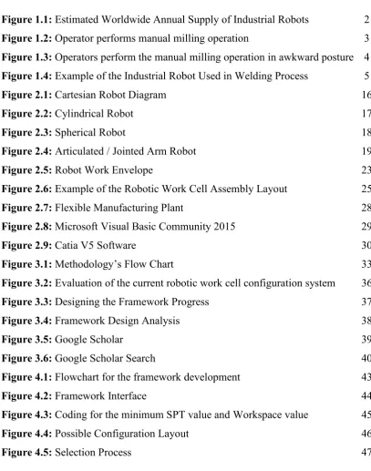
Figure 1.2:Main Components of Industrial Robots
(Source : American National Standards Institute (ANSI) American National Safety Standard ANSI/ RIA R15.06-1992. Industrial Robots and Robot Systems - Safety Requirements. American National
Standards Institute, Inc., 1430 Broadway, New York, New York 10018, 2012)
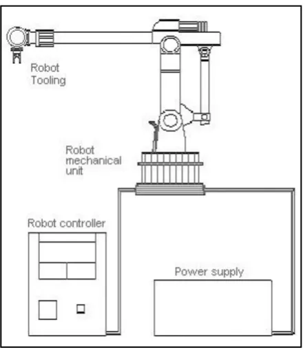
Figure 1.3 :A Typical Structure of an Articulated 6 DOF of Industrial Robot
(Source :IEEE Transaction On Automatic Control, Vol. AC-28, No.2, February 1983, An Anatomy of Industrial Robots and Their Control, by J.Y.S LUH, Senior Member, IEEE,)
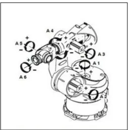
Figure 1.4 :Example of the Industrial Robot Used in Welding Process
(Source : Used robots.com/articles/viewing/welding robots increasing production for more than three decades)
The initiation of this study is to develop a framework for easy configuring the current and future robotic work cell at lower cost and minimum human involvement. This study are aimed to aid the future engineers to easily configure their robotics work cell based on the appropriate standards. The framework will capable to perform a simple algorithm of calculating the shortest process time and shown a two dimensional layout platform which prior to the development and configuration of the real robotic work cell. The outcomes of this framework will simplify the process of configuring the robotized factories in the future. It will also further enhance the human-industrial robot interaction as well as maximizing the usage of the industrial robots working within the current and future work cell. This will undoubtedly reduce cost and save future investment as well as reduce the time for developing a new robotic work cell.
1.2 Problem Statement
perform new or different tasks requires high cost of investment, more rigorous time and a lots of human involvement.
This study is essential to save the configuration time and cost for robotic work cell in manufacturing industries. The framework capable to show the flow of the process movement in 3D so that engineers can predict and calculate the efficiency of the design without based on field’s data to forecast the effectiveness of the system before installation. This study help in improving the flexibility and agility of the industrial robot in the work cell and utilized the industrial robot’s performance in production line. By the further study, this framework can aid in boosting the productivity and utilize the performance of the industrial robot in manufacturing industries.
This study eventually is to develop and validate the current issues through the development of an appropriate framework system is a software which purposely develop for reconfiguration of the industrial robot in manufacturing industries. This Framework will aid in developing, designing and giving the 2D layout for the view of the designed robotic work cell according to number of work cells (n) that been given, Degree of Freedom (DOF) of the industrial robot, industrial robot’s envelop, process description, types of end effector and industrial robot’s performance task.
1.3 Objectives
The objectives of this study are:
a) To evaluate the current configuration approach of the robotic work cell in manufacturing industry.
b) To develop the executable framework for the robotic work cell configuration.
1.4 Scope of Study
In order to ensure the feasibility of this study, the project scopes for developing the framework have been clarified. The development of this framework will be based on various criterion as follows:
1. The type of selected process for the project,
2. The type industrial robots and number of degree of freedom (DOF), 3. Number of industrial robots working within the work cell,
4. Dimension of the simulation framework,
5. The selected rules for the configuration framework, and
6. Programming and computer aided design (CAD) software for the development.
The selected type of process for the study is welding process. The process is chosen due to the fact that most of the industries utilizes their industrial robots for this type of process. The study will be focusing on the involvement of industrial robots within the welding process. This includes the structure of the gripper and tools used within the work cell. The propose framework will also depend on the type of industrial robots and its DOF selected. At this stage a six (6) DOF of an articulated type of industrial robots has been chosen. The main reason for choosing this type of industrial robots is due to its higher complexity that covers most of the other type of industrial robots. In this study, the structure and anatomy of various single 6-DOF articulated type of industrial robots will be taken into consideration.
Another consideration is the limitation for the number of industrial robots working within the work cell. For the purpose of this project, a maximum six (6) industrial robots are capped for the developed framework. Nevertheless, for the potential of future development of the framework, this limitation is temporary and the framework may have an endless number (‘n’ number) of industrial robots within its system. In order to ensure the framework will be much appreciated at the end of its development, the simulation work will be in three dimensional (3D) form. This 3D form will ensure a detail layout of the proposed robotic work cell can be proposed.
framework that includes Shortest Processing Time (SPT) rules as well as forecasting rules. This rules will be applied to the framework as a basis. The successions of utilizing the rules is the key for determining a better robot’s usability, performances and the cost for the implementation. Nevertheless, the rules implemented in the study will aids in improving the productivity of the product and optimized the system for better performance. For the development of the chosen rules, a suitable programming software packages are chosen.