MULTILEVEL INVERTER
MUHAMMAD SYAHIR AFIF BIN ABDUL RAHMAN
BACHELOR OF ELECTRICAL ENGINEERING (INDUSTRIAL POWER)
DECLARATION
I declare that this thesis entitled “HARMONICS MINIMIZATION OF A SINGLE
PHASE CASCADED H-BRIDGE MULTILEVEL INVERTER” is the result of my own
research except as cited in the references.
APPROVAL
I hereby declare that I have read through this thesis and found that is comply the partial fulfillment for awarding the degree of Bachelor of Electrical Engineering (Industrial Power)
i ACKNOWLEDGEMENT
In the name of Allah, The Most Beneficent, The Most Gracious and The Most Merciful. It is deepest sense gratitude of the Almighty that give me strength and ability to complete this Final Year Project report.
A special appreciation I give to my final year project supervisor, Prof. Madya. Ir. Dr. Rosli Bin Omar, whose give me a valuable guidance, lessons, support, and helped me to coordinate my project especially in writing this report.
Special thanks go to my family for their moral support to me and comfort me when I was in distress while to complete this project. Besides that, I would also like to acknowledge with much appreciation to all my friends who help and support me in order to complete my Final Year Project.
ii ABSTRACT
This project represent the research of harmonic minimization of a single phase cascaded H-bridge multilevel inverter (CHB-MLI). Multilevel inverter is used to combine a desired single or three-phase voltage waveform and also to minimize the harmonics in the electrical system. This project use cascaded H-bridge (CHB) topology due to least number of components use, output voltage level are doubled, and easy to controllled compared with diode clamp (DC) and flying capacitor (FC) topology. This research use three and five levels cascaded H-bridge multilevel inverter based on Newton-Raphson technique controller by using MATLAB/SIMULINK in order to reduce the harmonic in electrical system. The value of total harmonic distortion (THD) has been obtained based on the simulation design of three and five levels CHB-MLI.
iii ABSTRAK
Projek ini membentangkan kajian tentang pengurangan harmonik satu fasa penyongsang bertingkat cascaded H-bridge (CHB-MLI). Penyongsang bertingkat digunakan untuk menggabungkan satu atau tiga fasa gelombang voltan yang dikehendaki dan juga untuk mengurangkan harmonik dalam sistem elektrik. Projek ini menggunakan cascaded H-bridge (CHB) kerana bilangan komponen yang digunakan adalah sedikit, tahap voltan output adalah dua kali ganda, dan mudah untuk dikawal berbanding kapasitor terbang (FC) dan diod diapit (DC) topologi. Kajian ini menggunakan tiga dan lima tingkat penongsang bertingkat cascaded H-bridge berdasarkan kawalan teknik Newton-Raphson dengan menggunakan MATLAB/SIMULINK bertujuan untuk mengurangkan harmonik dalam sistem elektrik. Nilai jumlah herotan harmonic (THD) telah diperolehi berdasarkan reka bentuk simulasi tiga dan lima tingkat CHB-MLI.
iv TABLE OF CONTENTS
CHAPTER TITLE PAGE
ACKNOWLEDGEMENT i
ABSTRACT ii
TABLE OF CONTENTS iv
LIST OF TABLES vii
LIST OF FIGURES viii
1 INTRODUCTION
1.1 Project Background 1
1.2 Problem Statement 2
1.3 Objectives 3
1.4 Project Scope 3
1.5 Expected project outcome 4
2 LITREATURE REVIEW
2.1 Introduction 5
2.2 The Concept of Inverter 5
2.2.1 Types of Inverter Ouput Waveform 7 2.3 The Concept of Multilevel Inverter 9 2.3.1 Neutral Point Clamp Multilevel Inverter 9 2.3.2 Flying Capacitor Multilevel Inverter 11 2.3.3 Cascaded H-Bridge Multilevel Inverter 12
2.4 Description of Harmonics 14
v 2.5.2 Space Vector Pulse Width Modulation 17 2.5.3 Selective Harmonic Elimination Pulse 17 Width Modulation
2.5.4 Newton-Raphson Technique 18
2.6 The Concept of DSPTMS320F2812 19
2.7 Summary and discussion of the review 19
3 RESEARCH METHODOLOGY
3.1 Introduction of the Methods Utilized 20
3.2 Flow Chart of the project 21
3.3 Discussion on selected design using MATLAB/SIMULINK 23 3.3.1 Simulation of Optimization three-levels
cascaded H-bridge multilevel inverter by
using MATLAB/SIMULINK 23
3.3.2 The proposed Switching Scheme for three-levels cascaded H-bridge multilevel inverter 25 3.3.3 The Switching Block design for three-levels
cascaded H-bridge multilevel inverter by
using MATLAB/SIMULINK 26
3.3.4 Simulation of Optimization five-levels cascaded H-bridge multilevel inverter by using
MATLAB/SIMULINK 27
3.3.5 The proposed Switching Scheme for five-levels cascaded H-bridge multilevel inverter 29 3.3.6 The Switching Block design for five-levels
cascaded H-bridge multilevel inverter by
using MATLAB/SIMULINK 30
3.3.7 Simulation of Non-Optimization three-levels cascaded H-bridge multilevel inverter
by using MATLAB/SIMULINK 31
3.3.8 Simulation of Non-Optimization five-levels cascaded H-bridge multilevel inverter
vi 3.4 Mathematical Technique of Switching by using
Newton-Raphson 33
3.5 Discussion on the Proposed Hardware Design 36 3.5.1 Gate Drive for IGBT Switching 36 3.5.2 The Hardware for Single Phase Three Level
and Five CHB-MLI 37
3.5.3 Hardware Utilization Based on Digital
Signal Processor (DSP) 39
3.5.4 Experimental Prototype Circuits of Three
and Five Level CHB-MLI 40
3.6 Summary of the Method Use 41
4 RESULTS AND DISCUSSION
4.1 Introduction to Project Results 42 4.2 Simulation of a Single Phase CHB-MLI for Five
and Three level 42
4.2.1 Simulation Results for Optimization of a Single Phase Three-Level CHB-MLI design
with MI = 0.84 43
4.2.2 Simulation Results for Non-Optimization of a Single Phase Three-Level CHB-MLI design
with MI = 0.68 47
4.2.3 Simulation Results for Optimization of a Single Phase Five-Level CHB-MLI design
with MI = 0.84 51
4.2.4 Simulation Results for Non-Optimization of a Single Phase Five-Level CHB-MLI design
with MI = 0.68 55
4.3 Experimental Hardware Results of a Single Phase
Three-level CHB-MLI with Different Value of MI 59 4.3.1 Experimental Results for Optimization Single
Phase Three-level CHB-MLI with (MI = 0.84) 60 4.3.2 Experimental Results for Non-Optimization Single
vii 4.3.3 Experimental Results for Optimization Single
Phase Five-Level CHB-MLI with (MI = 0.84) 66 4.3.4 Experimental Results for Non-Optimization Single
Phase Five-Level CHB-MLI with (MI = 0.68) 70 4.4 Performance Comparison of Simulation and
Experimental Results of Three and Five level
CHB-MLI with Difference Value of MI 74
4.5 Summary of the Results 75
5 CONCLUSION AND RECOMMENDATION 76
REFERENCES 78
APPENDIX 80
[image:10.595.78.515.52.650.2]LIST OF TABLES
TABLE TITLE PAGE
2.1 Table of switching state for three-level NPC topology 10 2.2 Table of switching state for three-level FC multilevel inverter 12 2.3 Table of switching state for five-level CHB multilevel inverter 13 3.1 The values of switching angles based on modulation index 35 4.1 Performance comparison of simulation and experimental results of
viii LIST OF FIGURES
FIGURE TITLE PAGE
1.1 Single phase Cascaded H-bridge Multilevel Inverter 2 2.1 Basic connection of cascaded H-bridge inverter 6 2.2 Inverter output waveforms 8 2.3 Three -level Neutral Point Clamped topology 10 2.4 Three-level Flying Capacitor multilevel inverter 11 2.5 Five-level Cascaded H-Bridge multilevel inverter 12 2.6 Divided fundamental and harmonic waveforms 14 3.1 Flow Chart of the project 22 3.2 Modeling of optimize single phase three-level cascaded
H-bridge multilevel inverter by using MATLAB/SIMULINK 23 3.3 Scope for three-level cascaded H-bridge multilevel inverter
by using MATLAB/SIMULINK 24 3.4 Switching design for a three-level CHB-MLI by using
MATLAB/SIMULINK 25
3.5 Pulse generator block connected to switching signal in
three level CHB-MLI by using MATLAB/SIMULINK 26 3.6 Five-level cascaded H-bridge multilevel inverter design
using MATLAB/SIMULINK 27 3.7 Scope for five-level cascaded H-bridge multilevel inverter
by using MATLAB/SIMULINK 28 3.8 Switching design for a three-level CHB-MLI by using
MATLAB/SIMULINK 29
3.9 Pulse generator block connected to switching signal in
five level CHB-MLI by using MATLAB/SIMULINK 30 3.10 Modeling of non-optimize single phase three-level cascaded
ix 3.13 The design of a single phase three-level CHB-MLI 38 3.14 The design of a single phase five-level CHB-MLI 38 3.15 Digital Signal Processor (DSP) TMS320F2812 39 3.16 Set up of experimental prototype circuit of for three level
CHB-MLI 40
3.17 Set up of experimental prototype circuit for five level
CHB-MLI 41
4.1 Switching waveform for optimization three-level CHB-MLI 44 4.2 Output voltage waveform of optimization single phase
three level CHB-MLI 45 4.3 Harmonic spectrum for voltage output waveform of optimization three level CHB-MLI 45 4.4 Output current waveform of optimization single phase
three level CHB-MLI 46 4.5 Harmonic spectrum for current output waveform of optimization three level CHB-MLI 47 4.6 Switching waveform for non-optimization three-level
CHB-MLI 48
4.7 Output voltage waveform of non-optimization three level
CHB-MLI 49
4.8 Harmonic spectrum for voltage output waveform non-
optimization three level CHB-MLI 49 4.9 Output current waveform of non-optimization three level
CHB-MLI 50
4.10 Harmonic spectrum for current output waveform non-
optimization three level CHB-MLI 50 4.11(a) Upper switching waveform for optimization five-level
CHB-MLI 51
4.11(b) Lower switching waveform for optimization five-level
CHB-MLI 52
4.12 Output voltage waveform of optimization five level
CHB-MLI 53
x 4.13 Harmonic spectrum of optimization voltage output waveform
for five level CHB-MLI 53 4.14 Output current waveform of optimization five level CHB-MLI 54 4.15 Harmonic spectrum of optimization current output waveform for five level CHB-MLI 54 4.16(a) Upper switching waveform for non-optimization five-level
CHB-MLI 55
4.16(b) Lower switching waveform for non-optimization five-level
CHB-MLI 56
4.17 Output voltage waveform of non-optimization five level
CHB-MLI 57
4.18 Harmonic spectrum of non-optimization voltage output waveform for five level CHB-MLI 57 4.19 Output current waveform of non-optimization five level
CHB-MLI 58
4.20 Harmonic spectrum of non-optimization output current waveform for five level CHB-MLI 58 4.21 Switching waveform for optimization three- level CHB-MLI 60 4.22 Output voltage waveform for optimization of three-level
CHB-MLI 61
4,23 Harmonic spectrum of voltage output waveform for optimization of three-level CHB-MLI 61 4.24 Current output waveform for optimization of three-level
CHB-MLI 62
4.25 Harmonic spectrum of current output waveform for optimization of three-level CHB-MLI 62 4.26 Switching waveform for non-optimization three- level CHB-MLI 63 4.27 Output voltage waveform for non-optimization of three-level
CHB-MLI 64
4.28 Harmonic spectrum of voltage output waveform for non-
optimization three-level CHB-MLI 64 4.29 Current output waveform for non-optimization of three-level
CHB-MLI 65
xi 4.30 Harmonic spectrum of the current output waveform for non-
optimization of three-level CHB-MLI 65 4.31(a) Upper switching waveform for optimization of five-level
CHB-MLI 66
4.31(b) Lower switching waveform for optimization of five-level
CHB-MLI 67
4.32 Output voltage waveform for optimization of five-level
CHB-MLI 67
4.33 Harmonic spectrum of voltage output waveform for optimization
five-level CHB-MLI 68
4.34 Current and voltage output waveform for optimization of
five-level CHB-MLI 69
4.35 Harmonic spectrum of the current output waveform for
optimization of five-level CHB-MLI 69 4.36(a) Upper switching waveform for non-optimization of five-level
CHB-MLI 70
4.36(b) Lower switching waveform for non-optimization of five-level
CHB-MLI 71
4.37 Output voltage waveform for non-optimization of five-level
CHB-MLI 71
4.38 Harmonic spectrum of voltage output waveform for non-
optimization five-level CHB-MLI 72 4.39 Current and voltage output waveform for non-optimization of
five-level CHB-MLI 73
4.40 Harmonic spectrum of the current output waveform for non-
1 CHAPTER 1
INTRODUCTION
1.1 Project Background
In this chapter, a single-phase Cascaded H-bridge Multilevel Inverter (CHB-MLI) has been used to alternating current (AC) voltage waveform of the inverter output. For the ordinary inverter, the process of energy conversion is to convert Direct Current (DC) to Alternating Current (AC) [1]. The function of inverter is opposite the function of rectifier. The upgrade of inverter that nowadays used is called multilevel inverters. Multilevel inverter have more advantages compared to ordinary inverter. Multilevel inverters was invented with many levels that show the highest level give the best output. The main function for the multilevel inverter is to combine the desired output voltage waveform from several steps of voltage. There are three types of multilevel inverters topology that commonly used such as Cascaded H-Bridge Multilevel Inverter (CHB-MLI), Diode Clamp Multilevel Inverters (DC-MLI), and Flying Capacitor Multilevel Inverters (FC-MLI). This project use CHB-MLI in order to reduce harmonic because it easy to control and also the output voltages level are doubled the number of sources.
2 Figure 1.1: Single phase Cascaded H-bridge Multilevel Inverter
1.2 Problem Statement
Cascaded H-bridge multilevel inverter (CHB-MLI) is based on the series connection of the power cell and several H-bridge inverters to provide a sinusoidal output voltage. The main problem that always occurs in power electronics device is the harmonic content. In order to minimize the harmonic distortion, the switching angle has been used in the CHB-MLI for controlling the output voltage and current [3]. The major target is to decrease the total harmonic distortion (THD) in electronic devices. THD is the summation of all harmonic components of the voltage or current waveform that measured in a percentage. The higher the percentage of output voltage THD, the higher distortion that is present on the mains signal [4].
3
1.3 Objectives
The objective of this project are:
1) To study types of multilevel inverter topologies that mainly used to minimize harmonic distortion.
2) To investigate the harmonic minimization of optimization and non-optimization three-level and five-level single-phase Cascaded H-bridge Multilevel Inverter (CHB-MLI) by using MATLAB/SIMULINK.
3) To analyse a prototype of a single phase cascaded H-bridge multilevel inverter (CHB-MLI) based on Newton Raphson technique controller using DSP TMS320F2812.
4) To compare the differences of THD between simulation and hardware of three level and five level CHB-MLI.
1.4 Project Scope
4
1.5 Expected Project Outcome
5 CHAPTER 2
LITREATURE REVIEW
2.1 Introduction
In this study, a single phase cascaded H-bridge multilevel inverter (CHB-MLI) has been used to produce alternating current (AC) voltage waveform of the inverter output. There are three types of multilevel inverter topologies which are Diode Clamp (DC), Flying Capacitor (FC), and Cascaded H-Bridge (CHB) multilevel inverter. There are three types of inverter output waveform that commonly utilized which are square wave, modified sine wave and sine wave. Therefore, this study is to minimize the harmonic of a single phase cascaded H-bridge multilevel inverter by analysing its regulated output voltage.
2.2 The Concept of Inverter
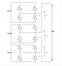
6 Figure 2.1: Basic connection of cascaded H-bridge inverter
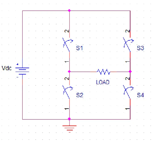
Based on figure 2.1, the voltage source supply is a DC source which is 240Vdc. The purpose of DC/AC power inverter is to convert the DC power supplied to AC power supplied which is usually operate at frequency from 50Hz to 60Hz. Each switches has its own function which is to turn ON or to turn OFF the inverter.
7 2.2.1 Types of Inverter Output Waveform
There are three types of inverter output waveform that commonly used which are square wave, modified sine wave, and sine wave. Firstly, the square wave usually be the output waveform for the AC load voltage of the inverter as shown in the figure 2.2. The only advantages of square wave are can work with ordinary light bulb and the cost used is cheap. The square wave attempt to cause many problems for motors which is increase the motor power loss and caused reduction of efficiency in the motor [7]. Therefore, the square waveform has a very high harmonic content that form noise in electronic device particularly in audio device such as microphone or speaker [8].
The modified sine wave or also known as quasi-sine wave that show the enhancement over the square wave as shown in figure 2.2. The modified sine wave is quite similar to a square wave because it has “stepping” looks but different in the shape that more relates to the sine wave [8]. The quasi-sine wave have high power efficiency, and actually are suitable used for running some types of motors and incandescent lighting. The peak output voltage varies with the battery voltage is the main problems or disadvantages of quasi-sine wave which can produce harmonic [9].
9
2.3 The Concept of Multilevel Inverter
Multilevel inverter mainly apply to combine a desired single or three-phase voltage waveform. By combining a few dc voltage sources, the desired multi-staircase output voltage can be acquired. There are three types of multilevel inverter topologies that commonly used nowadays which are neutral point clamp (NPC) or diode clamp (DC), cascaded H-bridge (CH), and flying capacitor (FCs). Cascaded H-bridge multilevel inverter has the higher output voltage and power levels (13.8k, 30MVA) compared to the other two topologies. Furthermore, cascaded multilevel inverter also has higher dependability due to its modular topology [11].
2.3.1 Neutral Point Clamp Multilevel Inverter
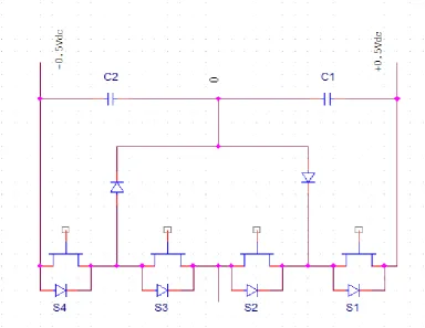
10 Figure 2.3: Three -level Neutral Point Clamped topology
Table 2.1: Table of switching state for three-level NPC topology
S1 S2 S3 S4 Vo
1 1 0 0 +0.5Vdc
0 1 1 0 0
[image:24.595.68.528.480.607.2]
![Figure 2.2: Inverter output waveforms [10]](https://thumb-us.123doks.com/thumbv2/123dok_us/65313.6188/22.595.126.472.112.408/figure-inverter-output-waveforms.webp)