This is a repository copy of An experimental and numerical investigation of chevron fin structures in serpentine minichannel heat sinks.
White Rose Research Online URL for this paper: http://eprints.whiterose.ac.uk/125443/
Version: Accepted Version Article:
Al-Neama, AF, Khatir, Z, Kapur, N orcid.org/0000-0003-1041-8390 et al. (2 more authors) (2018) An experimental and numerical investigation of chevron fin structures in serpentine minichannel heat sinks. International Journal of Heat and Mass Transfer, 120. pp.
1213-1228. ISSN 0017-9310
https://doi.org/10.1016/j.ijheatmasstransfer.2017.12.092
(c) 2017, Elsevier Ltd. Creative Commons Attribution Non-Commercial No Derivatives License.
[email protected] https://eprints.whiterose.ac.uk/
Reuse
Items deposited in White Rose Research Online are protected by copyright, with all rights reserved unless indicated otherwise. They may be downloaded and/or printed for private study, or other acts as permitted by national copyright laws. The publisher or other rights holders may allow further reproduction and re-use of the full text version. This is indicated by the licence information on the White Rose Research Online record for the item.
Takedown
If you consider content in White Rose Research Online to be in breach of UK law, please notify us by
[1]
International Journal of Heat and Mass Transfer (Impact Factor: 3.458)
An experimental and numerical investigation of chevron fin structures in serpentine
minichannel heat sinks
Ahmed F. Al-Neama a, b, *, Zinedine Khatir a, Nikil Kapur a, Jonathan Summers a, Harvey M. Thompson a
a Institute of Thermofluids, School of Mechanical Engineering, University of Leeds, LS2 9JT, United Kingdom.
b Department of Mechanical Engineering, Faculty of Engineering, University of Mosul, Iraq.
*Corresponding author. Email: [email protected]
Abstract
Water-cooled micro/minichannel heat sinks are an important component in managing the temperature of electronic components, particularly where high density of heat rejection is required. This study examines the potential to decrease the thermal resistance and enhance convective heat transfer of a serpentine heat exchanger, by introducing chevron fins which create secondary flow paths. This novel design is found to significantly reduce both the pressure drop across the heat exchanger and the total thermal resistance by up to 60% and 10%, respectively, and enhance the average Nusselt number by 15%. A three-dimensional conjugate heat transfer model is developed and validated against experimental measurements, before being used to carry out a parametric study involving the chevron oblique angle, secondary channel width and heat flux. The design of the serpentine minichannel with chevron fins is then optimised in terms of the minichannel width, minichannel number and chevron oblique angle. A 50 point Optimal Latin Hypercubes (OLHC) Design of Experiment (DoE) is constructed within the design variable space, using a permutation genetic algorithm, and accurate metamodels built using a Radial Basis Function (RBF) approach. A Pareto front is constructed which enables designers to explore appropriate compromises between designs with low pressure drop and those with low thermal resistance.
[2]
1. Introduction
The inexorable miniaturisation of electronic components and increase in electronic packaging density is driving the development of efficient cooling methods to preserve component lifespan and reliability. Single-phase micro/minichannel heat sinks are one promising option with the ability to dissipate high heat fluxes over small areas [1]. The use of water-cooled microchannel heat sink with straight rectangular microchannels was first introduced by Tuckerman and Pease [2] in 1981. In their experiments, they demonstrated that heat fluxes of up to 790 W/cm2 could be dissipated with a large pressure drop of 214 kPa across the heat sink for a substrate temperature rise of 71°C. They found that the heat transfer coefficient can be increased by decreasing the hydraulic diameter of the channels at the expense of increased pressure drop. After this pioneering work, several studies have investigated the fluid flow and heat transfer characteristics of microchannel heat sinks, see e.g. the recent review of Ghani et al. [3]. Flow boiling (Two-phase flow) microchannel heat sinks, on the other hand, have also been widely studied by researchers due to their ability to dissipate high heat fluxes with lower pumping powers compared with single-phase liquid microchannel heat sinks [4]. However, at higher heat fluxes, microchannel flow boiling suffers from pressure fluctuation and flow instabilities, which reduces and degrades the heat transfer characteristics in microchannel heat sinks [5].
Nomenclature
Base area of channel [m2] Fluid bulk temperature [oC]
Cross-sectional area of channel [m2] Inlet fluid temperature [oC]
Effective heat transfer area per channel [m2] Outlet fluid temperature [oC]
Surface area of fin [m2] Average channel base temperature [oC]
Bottom heated area of the MCHS [m2] Channel base temperature at thermocouple location (i = 1–4),
[oC]
Specific heat of fluid [J/kg.K] Velocity in microchannel [m/s] Hydraulic diameter [m] Heat sink width [m]
Convective heat transfer coefficient [W/m2.K] Channel width [m]
Substrate thickness [m] Secondary channel width [m] Channel height [m] Fin width [m]
Turbulent kinetic energy [m2/s2]
Thermal conductivity of fluid [W/m.K] Greek symbols
Thermal conductivity of copper block [W/m.K] Fin efficiency Turbulent thermal conductivity [W/m.K] Fluid density [kg/m3]
Heat sink Length [m] Dynamic viscosity of fluid [kg/m s] Channel length [m] Turbulent viscosity [kg/m s] Chevron fin length [m] Channel surface roughness [ ] Secondary channel length [m] Oblique angle [degree]
Number of microchannel Specific dissipation rate [1/sec] Number of chevron fin
Nusselt number Subscripts
Total pressure drop [Pa] Average
Fin pitch ( ) [m] Fluid (Water)
Perimeter of chevron fin [m] Inlet
The wetted perimeter Maximum
Volumetric flow rate [m3/sec] Outlet
Heat transfer rate [W] Solid
[3]
Fedorov and Viskanta [6], Qu and Mudawar [7] and Li et al. [8] carried out numerical studies of the fluid flow and heat transfer properties of a 1cm2 silicon wafer microchannel heat sink with straight rectangular microchannels that had previously been studied experimentally by Kawano et al. [9]. Li et al. [8]
highlighted the importance of including the dependence of the thermophysical properties of the fluid (i.e. density and viscosity) on temperature to accurately capture the linear increase in the channel wall temperature, as included in the study of Fedorov and Viskanta [6].
This rise in surface temperature limits the efficiency of the conventional straight microchannel heat sink and to enhance the convective heat transfer and achieve a more homogeneous temperature distribution, secondary flows can be produced by adding smaller channels between the main flow channels. Steinke and Kandlikar [10] and Kandlikar and Grande [11] suggested several techniques to promote heat transfer in microchannel heat sinks such as: increase surface area of heat transfer and improve the mixing flow using interrupted and staggered strip-fin design. Among these techniques, two techniques have been proposed by Steinke and Kandlikar [10] to generate secondary flow in a microchannel heat sink. The first was to add smaller secondary channels which induce flow between the main channels, while the second makes use of the Venturi effect. Both methods enhance the convective heat transfer by increasing fluid mixing without inducing significantly larger pressure losses. Advanced microchannel structures, such as stacked microchannels [12], tree-shaped microchannel network [13], and strip-fin microchannels [14,15] or micro-pin fin [16-19], have been also proposed to enhance temperature uniformity and reduce the pressure drop
[20].
[4]
transfer and pressure drop, and showed that the fin angle was the most influential parameter on the performance of the microchannel heat exchanger. Kuppusamy et al. [24] studied microchannel heat sink with alternating slanted passages which was proposed by Steinke and Kandlikar [10], and showed that the latter led to reductions in the average thermal boundary layer thickness, enhancing the thermal performance with a slight reduction in . Comparing their results with a conventional microchannel heat sink, they showed that the slanted passages enabled thermal resistance and pressure drop to be reduced simultaneously by 76% and 6% respectively.
Ghani et al. [25] studied numerically the fluid flow and heat transfer characteristics of microchannel heat sink with rectangular ribs and secondary oblique channels in alternating directions at different Reynolds number (Re) ranging from 100 to 500. This type of heat sink has been compared with microchannels with secondary oblique channel, microchannel with rectangular ribs and straight rectangular microchannel. The proposed design provides larger heat transfer area in comparison with the other three microchannel geometries, at the same time reducing the pressure drop caused by ribs by around 50%. Three parameters were selected to explore the effects of geometrical parameters on the hydrothermal performance of heat sink proposed which are: the relative secondary channel width, the relative rib width and the angle of secondary channel. The results revealed that the average Nusselt number and friction factor increase as the angle of secondary channel decreases and decrease as the relative secondary channel increases, while the friction factor increases as the relative rib width increases.
[5]
results indicated that a smaller oblique angle and smaller fin pitch both lead to improved heat transfer. Khan et al. [29,30]carried out an experimental investigation into single-phase heat transfer in commercial plate heat exchangers for symmetric and non-symmetric (mixed) chevron angle plates for Re ranging from 500 to 2500. Their experimental results demonstrated the significant effects of both chevron angle and Re on the heat transfer coefficient and friction factor and they used their results to propose a correlation to estimate Nusselt number and friction factor.
Three-dimensional numerical simulations have been conducted by Chai et al. [31] to investigate laminar flow and heat transfer characteristics in the interrupted microchannel heat sink with ribs in the transverse microchambers. In their study five different rib configurations are considered, including rectangular, backward triangular, forward triangular, diamond and ellipsoidal. Their findings indicated that the new interrupted microchannel with ellipsoidal ribs can effectively enhance the heat transfer coefficient along the flow direction compared with the other ribs and the conventional microchannel heat sink, due to redevelopment of the thermal boundary layer. The rectangular and backward triangular ribs in the transverse microchambers show the largest pressure drop compared with the other three configurations.
Al-Neama et al. [32] have very recently used complementary experimental and numerical methods to investigate the fluid flow and heat transfer characteristics of three different configurations of serpentine microchannel heat sink designs which they termed single (SPSMs), double (DPSMs) and triple (TPSMs) path multi-serpentine rectangular microchannels. They compared their performance, both experimentally and numerically, with an array of straight rectangular microchannels (SRMs) in terms of average Nusselt number ( ), total thermal resistance ( ) and . Their data showed that the SPSM design provides
the most effective heat transfer, followed by the DPSM and TPSM with the SRM heat sink having the
poorest heat transfer. It is found that the SPSM heat sink leads to a 35% enhancement of the and a
[6]
The above studies have demonstrated that flow obstructions and secondary flows in microchannels can enhance the thermal performance without significantly increasing pressure drop. The present study is the first to explore the benefits of using a new design of heat exchanger where chevrons fins within multiple serpentine minichannels are used to control the hydrodynamic and thermal boundary layers. Experimental and analytical methods are described in (section 2), followed by development of a conjugate heat transfer model (section 3). Results are presented in section 4 alongside a formal design optimisation study where three key design variables are considered. Conclusions are drawn in section 5.
2. Experimental Methodology
2.1. Experimental set-up and procedure
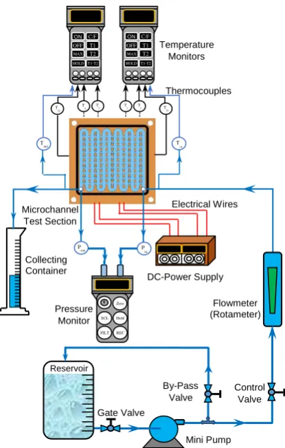
A schematic diagram of the main components of the experimental test rig is depicted in Fig. 1.Water from a 23 litre reservoir is pumped through the flow loop using a miniature diaphragm water pump. The flow rate is controlled by adjusting the pump speed through regulating the voltage using a DC-power supply and using a bypass flow loop and control valve to give a flow rate in the range 0.1 – 1.0 l/min, as measured on a flow meter.
The water temperature at the minichannel inlet and outlet was measured using K-type sheathed thermocouples with 0.5 mm probe diameter. The water inlet temperature was 20 oC. To measure the total differential pressure drop between the inlet and outlet of the minichannel heat sink (MCHS) models, a digital pressure meter was used (Comark model C9555) having a range of 0 to 2.1 bar. Two power film resistors of resistance 10 (MP9100 (TO-247)) were used as a heat source with the maximum power reaching 100W for each one. These are mounted at the bottom of the MCHS. The voltage and current input to the power film resistor heater was controlled by a DC power supply unit with an output range of 0-35V and 0-4A.
To minimise heat loss to the surrounding environment, the MCHS copper block was packed inside a bed of insulating fibres glass, and secured within a clear acrylic box of size (10×10×10) cm3 with a cover.
2.2. Design and fabrication of the MCHS test sections
[7]
was a multi-serpentine MCHS with plate fins (SMPF) (Fig. 2a) and the second a multi-serpentine MCHS with chevron fins (SMCF) (Fig. 2b), with an oblique angle of 30o. In order to facilitate a fair performance comparison between two different MCHS models, both heat sink models share the same channel depth ( ), channel width ( ), fin width ( ), footprint area ( ), heat sink depth ( ) and substrate thickness ( ). The MCHSs were fabricated from copper (thermal conductivity of 388W/m.K at 20°C), using a high-accuracy Computer Numerical Control (CNC) milling machine (FANUC ROBODRIL). With regard to the SMCF design, the continuous plate fin is broken into small chevron fins with 9 fins per row.
At the oblique angle ( ) of 30o, the length of the chevron fin ( ) is 1.3mm, whereas the fin pitch ( ) and
the secondary channel width ( ) were 2.3mm and 0.5mm, respectively. Fig. 2shows isometric and top views of the two types of MCHSs considered here. The measured geometrical dimensions for both sets of MCHS are listed in Table 1.
Around each minichannel top there is a groove made for an O-ring seal with a depth and width of 0.7mm and 1.0mm respectively to prevent water leakage. Each MCHS sample was assembled with an Acrylic Perspex plastic sheet cover which is held onto the copper block by four stainless steel mounting screws (M3×0.5) and sealed with an O-ring. Two 3mm holes with depth of 3.0mm were drilled on the top side surfaces of the plastic covers and male run tee union adapters (M3×0.5) are fixed into these threaded holes to provide the inlet and outlet for the water, and also to measure the temperature of the water inlet and outlet from the MCHS test section. To measure the differential pressure drop between the inlet and outlet MCHS test section, a further two 3.0mm holes with depth of 3.0mm were drilled into the sides of the plastic cover (at the inlet and outlet positions), with barb fitting adapters (M3×0.5) used to connect the pressure gauge, see Fig. 3.
[8]
were inserted in the copper block at a distance of 1mm below the minichannel base until it reaches half the width of the MCHS specimen. The locations of the thermocouple holes, as measured from the inlet of the MCHS and along its length are shown in Fig. 3. Thermal paste was used to fill the holes to ensure accurate temperature measurement.
Sa and Sq which are respectively the Average Roughness and Root Mean Square Roughness are measured for both MCHS models using the BRUKER-NPFLEX-LA 3D Surface Metrology System, and these were found to be respectively and for both models. In the experiments, the relative surface roughness, , where and are respectively the surface roughness and hydraulic diameter of
the minichannel, for both serpentine MCHS test sections studied is therefore . Kandlikar et al. [34]studied the effect of surface roughness on pressure drop and heat transfer characteristics in 0.62 and 1.067mm diameter stainless steel micro-tubes. The relative surface roughness for the larger diameter tube ranged from 0.00176 to 0.0028, and their results showed that the effects of varying surface roughness on pressure drop and heat transfer were insignificant. Since the relative roughness of the minichannels tested in the present experimental work were smaller than those of Kandlikar et al. [34] therefore it is assumed that the surface roughness ( ) does not have a significant effect on the pressure drop and heat transfer coefficient in the present study.
2.3. Experimental measurements and data analysis
2.3.1. Heat transfer analysis
Before conducting any experiments, the rate of heat loss that is dissipated from the MCHS specimen to the surroundings was first determined. In the present work, the procedure described in [32] has been used, and the maximum average heat loss was found to be approximately 6% of the input power from each model.
The average heat transfer coefficient ( ) can be calculated from Newton's law of cooling as:
(1)
where is the total heat supplied into the MCHS, while represents the surface area available for heat
[9]
fourth wall (Top) is assumed to be adiabatic. The average channel base temperature ( ) can be obtained
by:
(2)
Since direct measurement of the minichannel base temperature is challenging, it is determined by assuming one-dimensional steady state heat conduction between the thermocouple location ( ) and the minichannel base in the y direction, the local minichannel base temperature ( ) can be evaluated by [26]:
(3)
represents the temperature closer to the minichannel base wall which was measured experimentally
using a thermocouple, the subscript i denotes the location of thermocouple used to measure the minichannel base temperature. denotes the area of the substrate subjected to the heat flux, while is the thermal conductivity of the heat sink material, and is the distance between the bottom wall of the minichannel and the thermocouple that is embedded to measure as shown in Fig. 3.
The corresponding average Nusselt number can be determined by:
(4)
where represents the fluid thermal conductivity which is evaluated at the average fluid temperature
( ). and are respectively the fluid inlet and outlet temperature which
are measured by the thermocouples positioned just before and after the heat sink test section. denotes
the minichannel hydraulic diameter
, while and are respectively the wetted perimeter and the cross sectional area of the minichannel.
2.3.2. Total thermal resistance
The total thermal resistance ( ) of the serpentine MCHS can be determined as follows:
[10]
where is the surface maximum temperature of the heat sink. The total thermal resistance of the
heat sink comprises three main components which are conductive ( ), convective ( ) and bulk
temperature-rise ( ) thermal resistances [35], and can be expressed by:
(6)
where is the total mass flow rate of coolant through the minichannel ( ). The denotes
the specific heat capacity of the fluid which is evaluated at . In this study, the conductive thermal
resistance remains constant since the substrate thickness of the heat sink is unchanged, while convective and bulk thermal resistances reduce with increasing water flow rate, resulting in lower total thermal resistance. The is caused by the heating of the liquid as it flows through the minichannels and absorbs heat [35].
2.3.3. Pressure drop analysis
A digital gauge pressure was used to measure the total pressure drop ( ) directly using two plastic tubes connected to the barb fitting adapters, see Fig. 3. The serpentine MCHS structure has minichannels and a total fins (U-bends), see Fig. 2a. Hence the total pressure drop is caused by contributions from friction in the straight minichannels and from the U-bends. The procedures used to calculate in the present experimental work are described in detail in the Ref. [32].
2.4. Experimental uncertainty
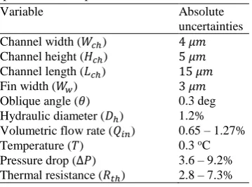
In the present work, the ASME standard [36] and Root-Sum-Square (RSS) methods described by Coleman and Steele [37] were used to estimate the experimental uncertainties, . In the experiments, an electronic digital Vernier caliper is used to measure various geometric dimensions of the MCHS test sections. Uncertainties for the main parameters are tabulated in Table 2.
3. Computational model
3.1. Governing equations
[11]
both the laminar and turbulent flow regimes; (3) the effects of radiation and natural convection are negligible. The Reynolds number ( ) can be calculated as:
(7)
where and are respectively the density and viscosity of the fluid, while denotes the inlet
velocity to the tube having hydraulic diameter ( ) of 1.5mm for both MCHS models, see Fig. 3. Flow is modelled using the following steady continuity and Navier-Stokes momentum equations:
(continuity equation) (8)
(momentum equation for laminar flow) (9)
(momentum equation for turbulent flow) (10)
where and are respectively the fluid velocity vector and the fluid pressure (Pa), and denotes the unit diagonal matrix. In the present study the standard - turbulence model has been used to solve the governing equations, as this model has been shown to capture the physics well for other similar heat transfer studies [38,39]. The - model introduces two additional variables: the turbulent kinetic energy, ), and specific dissipation rate, . The transport equations for and used in the CFD model are based on those given by Wilcox [40]:
(11)
(12)
The production term and the turbulent viscosity are defined by:
, (13)
while the empirical turbulent model constant parameters are [32]:
The heat transfer (energy) equations for the liquid and the solid can be expressed respectively as:
[12]
(15)
where is the turbulent thermal conductivity , and is the turbulent Prandtl number
(using Kays–Crawford [41,42]). Eq. (14) is the energy equation for the liquid in three-dimensional, steady and turbulent flow, with for laminar flow. The above flow and heat transfer equations are solved within COMSOL Multiphysics version 5.2 [42].
3.2. Boundary conditions
The computational domain and boundary conditions are highlighted in Fig. 4.
No-Slip velocity boundary condition are used at solid walls and wall temperatures are defined by
. At liquid-solid boundaries the conductive and convective heat transfer to the fluid are coupled by imposing heat flux continuity at the interface between the fluid and the solid walls [7]as shown in Fig. 4(a), where and are respectively the interface temperature for the solid and the liquid. The
boundary conditions of inlet flow are (m3/s) and , while the outlet flow boundary
condition is , where is pressure at the outlet (0 Pa), as shown in Fig. 4(b).
Except at the bottom of the MCHS, all the outer surface boundaries are considered to be adiabatic. Heating power, , was applied at the bottom surface of the MCHS using ( ), where denotes the outward normal vector on the boundary of the domain. To define the thickness and thermal conductivity of a material (Ethoxy) located between the heater and the base of the heat sink, a thin layer boundary condition was employed since COMSOL Multiphysics has the ability to define this boundary as shown in
Fig. 4(c). The thermal conductivity ( ) and thickness ( ) of Ethoxy layer are respectively 2.2 W/(m.K)
and .
The thermo-physical properties of water including , , and depend on temperatures is presented
as shown in Eqs. (16-19)[42]:
(16)
[13]
(18)
(19)
where the unit of is K. The thermal conductivity of copper, , is set as a constant of 400 W/m.K in the computations.
4. Results and discussion
4.1. Grid sensitivity
Grid-dependence of the numerical solutions was tested for the SMPF and SMCF designs. The effects of grid density on the predicted values of the temperature between the heater and heat sink bottom ( )
and the total pressure drop ( ) for the MCHS are listed in Table 3, where grid 1 is the coarsest and grid 4 is the finest for each MCHS design. Flow in the whole MCHS was solved by employing meshes with additional refinement around the bends and chevron fins, while the remained geometry was meshed with a fine mesh element size (see Fig. S4 in the Supplementary Data). The numerical simulations are carried out at water flow rate of (Uin = 1m/s), water inlet temperature set at 20°C and an input power of 100W supplied underneath the MCHS. The heat sink used for both models has the same parameters used
in the experimental work, see Fig. 2. The deviation percentage, E, of and are calculated with
respect to the solutions on grid 4 in each case; these are small (~2%), thus grid 3 is employed for all MCHS computations reported below as a suitable compromise between efficiency and accuracy.
The accuracy of the solution is affected by the mesh quality, and COMSOL has the ability to check the mesh element quality automatically for both laminar and turbulent flow regimes. To avoid the effect of low quality on the solution, mesh quality in the laminar flow regime should be larger than 0.1, and in the present
numerical simulation was 0.65. For the turbulent flow regime, the value of must be checked,
where is the wall lift-off and is the fluid kinematic viscosity ( ). is the friction velocity (
), where denotes the Von Karman constant and it is equal to 0.418 for wall lift-off, while is an
[14]
The value of has significant effect on the accuracy of the solution, and should be within the recommended range ( ) [43]. For the highest accuracy, the value of should be equal to 11.06 [42] which is the same value of the present numerical work.
4.2. Validation against previous studies
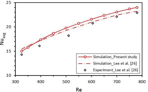
The numerical method was validated by comparison with the experimental results of Lee et al. [26] for oblique fins in microchannels. Water was used as the coolant with flow rates varying from 375 to 950 ml/min, corresponding to a Reynolds number ( ) of 325-780. A uniform heat flux of 65 W/cm2 was applied in the bottom of the copper heat sink. To reduce the size of the computational problem, symmetry was exploited, and flow was solved in a domain comprising using full width oblique fins and two half– width main microchannels [27]. Results were obtained in terms of the versus as shown in Fig. 5
(see Eq. (4)), and these agreed reasonably well with those of Lee et al. [26] with a maximum discrepancies between their numerical and experimental results of less than 5% and 8%, respectively.
4.3. The effect of inlet volumetric flow rate ( )
The effect of inlet volumetric flow rate ( ) for both of the proposed serpentine MCHSs designs has been studied in terms of total pressure drop ( ), total thermal resistance ( ) and average Nusselt number
( ) both experimentally and computationally. Fig. 6 depicts the experimental data and numerical
prediction of for both MCHSs for volumetric flow rates ranging from 0.053 to 0.318 l/min and input power of 100 W. Single-phase laminar and turbulent flow regimes are considered depending on the hydraulic diameter of the water inlet tube, which is 1.5mm for both MCHS models, see Fig. 4b. The oblique angle ( ), the fin length ( ) and the fin pitch ( ) of chevron fins are respectively 30o, 1.3mm and 2.3mm,
[15]
With regard to , the experimental results indicated that using SMCF design led to typically a 11% reduction compared with the SMPF, from 0.31 to 0.276 K/W at (Uin = 1.5 m/s), see
Fig. 7. This decrease in the may be due to the re-initialization of both the hydrodynamic and the thermal boundary layers at the leading edge of each oblique fin, which in turn lead to decreases the thickness of the boundary layers as will be explained later in Fig. 17. Additionally, the effective heat transfer area ( ) for SMCF design (2243.6 mm2) is roughly 17.7% larger than the SMPF one (1846.5 mm2). Also, it
can be seen from the Fig. 7 that decreases monotonically with as a result of the decrease in the surface temperature of the MCHS. Good agreement was found between the experimental data and corresponding numerical prediction for both MCHSs, with an average discrepancy around 3.2% for both the SMCF and SMPF models.
Fig. 8 depicts the effect of on the thermal resistance for both SMPF and SMCF heat sinks. varies from 0.053 to 0.201 l/min with an input power of 100W. The experimental total thermal resistance for the present work is presented according to Philips's analytical equation [35], see Eq. (6). As can be seen from this figure, good agreement was achieved between experimental and analytical equation with an average discrepancy of around 8% for both heat sinks. The three components of the thermal resistances have been plotted ( , and ). The latter two components are reduced as increases; is constant since the heat sink base is unchanged. The is reduced due to the higher flow rate, while the reduces because of the higher heat transfer coefficient. Note that is higher than the by 33% for SMPF and the difference reduced to 28% with SMCF design, and this due to increasing the
of the SMCF heat sink compared with SMPF.
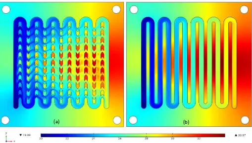
Fig. 9 shows the contours of pressure along the channel flow at the mid-depth plane of the channel ( )
[16]
Fig. 10 shows the temperature contours at the mid-depth plane of the channel ( ) for a of 0.159 l/min with input power of 100 W for both the SMPF and SMCF heat sink models. The temperature distributions on the heating surface of the two MCHSs are clearly different, and the wall temperature increases with the flow length due to the sensible heat gain by the coolant. For the SMCF heat sink, the figure demonstrates that breaking the continuous serpentine fin into chevron shaped fins has a significant influence on the temperature field, because it induces better fluid mixing between the main and secondary flow channels due to the formation of a secondary flow vortex (as will be explained later in Fig. 16), leading to a high temperature gradient over the heating microchannel wall. Overall, the chevron fins lead to a larger convective heat transfer area, thereby enhancing the heat transfer.
Fig. 11 plots the average Nusselt numbers ( ) obtained from experiments of both of the SMPF and
SMCF heat sinks versus volumetric flow rates ( ) with input power of 100W.
To calculate the values for the two different serpentine MCHS configurations, Eq. (4) was used
while Eq. (1) was used to determine the average heat transfer coefficient ( ). Generally, the for
both configurations increase with as the thermal boundary layer thickness decreases with the increased fluid velocity [28]. However, the heat transfer for the enhanced microchannel with chevron fins is higher than the SMPF heat sink. For example, at of 0.159 l/min, the of the SMCF heat sink is 14%
higher than that of SMPF heat sink.
It should be noted that the average experimental Nusselt number for both configurations are almost the same difference when , while the increases to as much as 9%, from 17.3 to 18.8,
as increases beyond 0.212 l/min. In addition to experimental data, simulation results of both SMPF and SMCF are plotted in Fig. 11 for comparison purposes. In fact, the simulation predictions are in good agreement with the experimental results, with average discrepancy of 3.2% for both heat sinks.
The average channel base temperatures ( ) measured are plotted in Fig. 12 at different with input
power of 100W. The was measured by the four thermocouples closest to the minichannel base (see
Eq. (2) and Fig. 3). Generally, the decreases with for both MCHS designs, and SMCF has lower
compared with SMPF heat sink. At of 0.053 l/min, the of the SMCF is 15% lower than
[17]
convective heat transfer increases with for both models. The rationale behind the reduction of the wall temperature in the SMCF belong to the combined effects of thermal boundary layer re-development at the leading edge of each chevron fin and divers a fraction of fluid from the main channel to the secondary channel through the chevron fin, which resulting in better heat transfer. In addition, good agreement was found between experimental and computational data for both heat sinks proposed with average discrepancy of 2.4%.
4.4. Performance evaluation analysis
The experimental and numerical results for fluid flow and heat transfer showed that the SMCF heat sink design can simultaneously reduce both of the overall thermal resistance and pressure drop with
enhancement in compared with the SMPF heat sink model. Therefore, the benefits and
disadvantages of the new serpentine MCHS are assessed using a standard criterion, the thermal performance factor ( ) based on the same pumping power consumption, as defined in [44,45]:
(20)
where, , and , represent the average Nusselt number, pressure drop of comparison model (SMCF) and standard model (SMPF), respectively. The values are plotted as
functions of as shown in Fig. 13, which also presents the average heat transfer enhancement parameter ( ) and pressure drop penalty parameter ( ) at different for the SMPF and SMCF heat sinks. The
and were defined as the average Nusselt number and total pressure drop obtained from experiments of the SMCF divided by those corresponding to the SMPF, respectively [46].
As shown by the line, since the value is always >1, this implied that the SMCF is superior to SMPF in heat transfer performance. Also, it is seen that the decreases when . For the case of
[18]
values are always >1 which implies that the heat transfer performance increases faster than the total
pressure drop reduces. It should be noted that at higher , the heat transfer performance was improved by around 15% for the SMCF compared to the SMPF while the total pressure drop decreased by only about one third. This shows that this SMCF can improve energy efficiency significantly through reduced pumping power.
4.5. The effect of oblique angle ( ) variation
To study effect of the oblique angle ( ), solutions are obtained for and The MCHS parameters such as surface area, minichannel height ( ), minichannel width ( ), fin width
( ), fin length ( ), fin pitch ( ) and thickness base plate ( ) are constant for all oblique angles, taking
values of 20×20 mm2, 2mm, 1mm, 1mm, 1.4mm, 2mm and 0.5mm respectively, yielding ten parallel minichannels. The volumetric flow rate for these simulations was fixed at 0.2 l/min (Uin = 1.67m/s) with constant heat flux of 100 W/cm2 supplied underneath the heat sink. Fig. 14a quantifies the average secondary flow rate diverted from the main minichannel to the secondary microchannel along the
streamwise direction at and , and the eight secondary microchannels of the minichannel located in the middle heat sink have been chosen for comparison as highlighted in Fig. 14b. As can be seen when increases, the secondary flow rate also increases. For example, at the average percentage of secondary flow across the heat sink is only 11.4%, indicating that the majority of the flow is confined in the main minichannel and only a small portion of flow is diverted to the secondary microchannel. For
, this percentage increases to 16.6%.
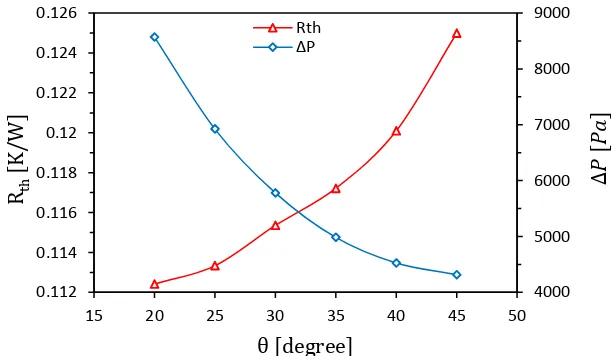
Fig. 15 shows predictions of the pressure drop ( ) and total thermal resistance ( ) for six different angles used with a constant volumetric flow rate of and uniform heat flux of 100 W/cm2
[19]
Fig. 15also shows that decreases as decreases: decreases from 0.125 K/W at to 0.112
K/W at . This decrease in for smaller values is caused by an increase in the convective heat
transfer area ( ). For example, when is decreased from 45o to 20o, increases by 30.6%, from
1212.8 mm2 at to 1583.7 mm2 at . Decreasing also leads to a reduction in the secondary microchannel width ( ), which in turn leads to larger flow velocities in the main straight and curved minichannels, which in combination with the larger leads to enhanced heat transfer and
correspondingly lower values of .
Fig. 16 shows predicted velocity vectors for the SMCF heat sink design for and . The
vectors are taken at the mid-depth plane of the minichannel ( ) at and uniform heat flux of 100W/cm2. The chevron fin located near the main curved minichannel was enlarged to show the flow structures more clearly. The figure shows that when decreases from to the velocity in the main curved minichannel increases, since a greater proportion of the water flows in the mainstream minichannel due to the decreasing secondary microchannel width. In all cases, it can be seen a vortex is generated at the lower corner of the chevron fin. The recirculating flow region becomes bigger as increases and this diverts more liquid from the mainstream minichannel into the secondary microchannel (see Fig. 14a). This is due to a wider secondary microchannel which led to increases the momentum of the secondary flow and disrupts the recirculation region and boundary layer development. This behaviour has also been reported by Lee et al. [26], who concluded that it enhances fluid mixing and heat transfer.
Fig. 17 shows the velocity vectors in the SMCF heat sink design which is taken at the first two of the minichannels from the inlet side at the mid-depth plane of the channel ( ) in x-y plane with
, and heat flux of 100 W/cm2. As seen in the figure, fluid is diverted from the secondary microchannel to the main flow of the adjacent minichannel enhancing fluid mixing. In addition, the presence of the chevron fin in the enhanced microchannel configuration disrupts the momentum and thermal boundary layers at the leading and trailing edge of each section, and this re-development of the boundary layer reduces its thickness, promoting improved heat transfer.
The effects of on convective heat transfer at different are shown in Fig. 18. It was observed that
[20]
larger chevron oblique angle which degrades convective heat transfer. This phenomenon is consistent with the finding by DeJong and Jacobi [47]. They found that the size of recirculation zone was observed to increase with louver angle and decreased heat transfer significantly of louvered-fin arrays. Additionally, the heat transfer area has significant effect on the heat transfer performance since the increases as
decreases in the SMCF heat sink. From the Fig. 18 it is found that the lines of for all have the
same gradient and those for was higher compared with others. For example, at
, the at , is 15% higher than that of .
4.6. The effect of the secondary microchannel width ( )
Fig. 19 shows the effect of varying the secondary microchannel width on the pressure drop and total thermal resistance at a volumetric flow rate = with uniform heat flux of 100 W/cm2.
Five different values of were analysed, and both the minichannel width and fin width were set at 1 mm, while the chevron fin length varies between 0.8 mm and 1.6 mm to produce designs with
= 0.2, 0.3, 0.4, 0.5 and 0.6 mm. The fin pitch and the oblique angle for these five cases are fixed at 2 mm and 30o, respectively. Fig. 19 shows that increases monotonically when decreases; for
example, increases threefold from 3110.4 Pa at to 9462.1 Pa at . This is due to the fact that the majority of the flow for is confined in the main minichannel, with only a small fraction being diverted to the secondary microchannel.
When decreases from 0.6 mm to 0.2 mm, also decreases by 42%, from 0.19 K/W at
to 0.11 K/W at . This is due to an increase in convective heat transfer area ( ) between
the coolant and the minichannel wall and it was found that when the decreases from 0.6 mm to 0.2 mm,
increases by 18%. Additionally, this increase in leads to a reduction in the maximum surface
temperature ( ), which also decreases the thermal resistance. For example, for the SMCF
[21]
These results suggest that reducing can disrupt the thermal boundary layer more effectively, reducing the wall temperature and leading to higher heat transfer and reducing the .
The effects of on convective heat transfer at different is illustrated in Fig. 20 with heat flux of 100 W/cm2. As shown in figure the increases monotonically with for all , while it decreases with
increasing . At higher volumetric flow rate ( ), it is shown that the is increases
by 29% when decreasing from 0.6 to 0.2 mm, and this contributes to the increase of the convective heat transfer area as described previously. Additionally, when decreases the flow rate diverted from the main minichannel to the secondary microchannel also decreases which in turn leads to larger velocities in the minichannel and hence fluid mixing and heat transfer.
4.7. SMCF Design Optimisation
In electronics, heat sinks are designed to maintain processors below critical temperatures for minimal energy input into the system. This final section considers the optimisation of the SMCF heat sink design subject to the conflicting objectives of minimising both and . Three design variables are used,
namely the minichannel width, , the number of minichannels, , and the oblique angle of the chevron
fin, , in the ranges of , and . The heat sink
surface area, substrate thickness, minichannel depth ( ), fin length ( ) and fin pitch ( ) were fixed to be
[22]
(21)
where Li,j is the Euclidean distance between the points i and j ( i ≠ j ) and N=50 is the number of DoE points. Metamodels for and throughout the design space are built using a Radial Basis Function (RBF) method [50,51], where a cubic radial power function is used to determine the weighting ( ) of points in the regression analysis at each point:
(22)
The parameter is the normalised distance of the metamodel prediction location from the sampling point. The Pareto front is calculated using a multi-objective genetic algorithm (MOGA) approach based on
[52,53]. Points on the Pareto front are non-dominated in the sense that it is not possible to decrease any of the objective functions (i.e. or without increasing the other objective function. Fig. 21 shows the values of the and at all of the DoE points and the Pareto front that is constructed from them.
Table 4 shows seven points on the Pareto front (P1-P7) and a comparison between the calculated values of and from the metamodels at these points and from the full numerical simulations (CFD). Agreement between the metamodel and full numerical predictions is good in all cases, demonstrating the accuracy of the metamodelling approach adopted here. Table 4 also shows the compromise that must be struck between low pressure drop and low thermal resistance. It shows, for example, that achieving the relatively low thermal resistance at P1 (0.124) requires more than five times the pressure drop than for the higher thermal resistance of 0.154 at P7. Clearly the most appropriate compromise depends on the particular manufacturing and operating cost and functionality requirements for a specific heat sink.
5. Conclusion
[23]
The experimental and numerical results have demonstrated that the total thermal resistance, , of both MCHS designs decrease monotonically with water flow rate due to the increased convective heat transfer. The experiments have shown the SMCF design can reduce compared to the SMPF design by around 11% for and that decreasing the chevron fin oblique angle, , from to can reduce by a further 10%. At the same time, the inclusion of the chevron fins reduces the overall pressure
drop; with and the pressure drop is reduced to approximately one third of that for the corresponding SMPF heat sink. This demonstrates that introducing chevrons into the serpentine MCHSs, it is possible to reduce the thermal resistance without paying the penalty of additional pressure drop; indeed the chevron design significantly reduces the pressure drop as well. The secondary microchannel width, , is also very influential. For example, when is decreased from 0.6mm to 0.2mm at , reduces by 42%, mainly as a result of increasing the convective heat transfer area and disturbances to the thermal boundary layer.
The Pareto front from the formal design optimisation of a SMCF heat sink demonstrates vividly the compromise that must be struck between the conflicting objectives of low thermal resistance and low pressure drop designs. The numerical analysis predicts that reducing thermal resistance by 19.5% (from 0.154 to 0.124) is at the expense of a greater than fivefold increase in pressure drop. In practice, the most appropriate design would balance the competing demands for low manufacturing and operating costs against the requirements on thermal resistance that deliver the critical cooling performance objectives.
Acknowledgements
[24]
References:
[1] G. Wang, D. Niu, F. Xie, Y. Wang, X. Zhao, G. Ding, Experimental and numerical investigation of a microchannel heat sink (MCHS) with micro-scale ribs and grooves for chip cooling, Applied Thermal Engineering 85 (2015) 61-70.
[2] D.B. Tuckerman and R.F.W. Pease, High-performance heat sinking for VLSI, IEEE Electron Device Letters EDL
2 (5) (1981) 126–129.
[3] I.A. Ghani, N.A.C. Sidik, N. Kamaruzaman, Hydrothermal performance of microchannel heat sink: The effect of
channel design, International Journal of Heat and Mass Transfer, 107 (2017) 21–44.
[4] B. Agostini, M. Fabbri, J.E. Park, L. Wojtan, J.R. Thome, State of the art of high heat flux cooling technologies, Heat Transfer Eng. 28 (2007) 258-281.
[5] K. Balasubramanian, P.S. Lee, C.J. Teo, S.K. Chou, Flow boiling heat transfer and pressure drop in stepped fin microchannels, International journal of heat and mass transfer 67(2013) 234-252.
[6] A.G. Fedorov, R. Viskanta, Three-dimensional conjugate heat transfer in the micro-channel heat sink for
electronic packaging, International Journal of Heat and Mass Transfer 43 (3) (2000) 399–415.
[7] W. Qu, I. Mudawar, Analysis of three-dimensional heat transfer in micro-channel heat sinks, International Journal
of Heat and Mass Transfer 45 (2002) 3973–3985.
[8] J. Li, G.P. Peterson, P. Cheng, Three-dimensional analysis of the heat transfer in a micro-heat sink with single
phase flow, International Journal of Heat and Mass Transfer 47 (2004) 4215–4231.
[9] K. Kawano, K. Minakami, H. Iwasaki, M. Ishizuka, Micro channel heat exchanger for cooling electrical equipment, Application of Heat Transfer in Equipment, Systems and Education, ASME HTD-361-3/PID-3,
(1998) 173–180.
[10] M.E. Steinke, S.G. Kandlikar, Single-phase heat transfer enhancement techniques in microchannel and minichannel flows, in: Second International Conference on Microchannels and Minichannels, Rochester, NY
USA, (2004) 141–148.
[11] S.G. Kandlikar, W.J. Grande, Evaluation of single phase flow in microchannels for high heat flux chip
cooling-thermohydraulic performance enhancement and fabrication technology, Heat Transf. Eng., 25 (2004) 5–16.
[12] Y. Joshi, X. Wei, Micro and Meso-scale Compact Heat Exchangers in Electronics Thermal Management - A Review, in: R.K. Shah, M. Ishizuka, V.V. Wadekar (Eds.), Proceedings of Fifth International Conference on Enhanced, Compacted and Ultra-Compact Heat Exchangers: Sciebcd, Engineering and Technology, Engineering Conferences International, Hoboken, NJ, USA, 2005, pp. 162–179, September.
[13] F.J. Hong, P. Cheng, H. Ge, T. J. Goh, Conjugate heat transfer in tree-shaped microchannel network heat sink for integrated microelectronic cooling application, International Journal of Mass and Heat Transfer, 50 (2007) 4986–4998.
[14] S.G. Kandlikar, H.R. Upadhye, Extending the Heat Flux Limit with Enhanced Microchannels in Direct Single Phase Cooling of Computer Chips, 21st IEEE-THERM Symposium, 5–17 (2005) 8–15.
[15] E.G., Colgan, B., Furman, M., Gaynes, W.S., Graham, N.C., LaBianca, J.H., Magerlein, R.J., Polastre, M.B., Rothwell, R.J. Bezama, R., Choudhary, K.C., Marston, H., Toy, J., Wakil, J.A., Zitz, R.R., Schmidt, A practical implementation of silicon microchannel coolers for high power chips, IEEE Transaction on Components and Packaging Technologies, 30 (2) (2007) 218-225.
[16] Y. Peles, and A. Kosar, C. Mishra, C.J. Kuo, B. Schneider, Forced convective heat transfer across a pin fin micro heat sink, International Journal of Heat and Mass Transfer, 48 (2005) 3615–3627.
[25]
[18] A. Kosar, C. Mishra, Y. Peles, Laminar flow across a bank of low aspect ratio micro pin fins, ASME Journal of Fluids Engineering 127 (2005) 419–430.
[19] A.M. Siu-Ho, W. Qu, F.E. Pfefferkorn, Experimental study of pressure drop and heat transfer in a single-phase micro-pin-fin heat sink, ASME Journal of Electronic Packaging 129 (2007) 479–487.
[20] F. Hong, P. Cheng, Three dimensional numerical analyses and optimization of offset stripe fin microchannel heat sinks. International Communications in Heat and Mass Transfer, 36 (2009) 651-656.
[21] J.L. Xu, Y.H. Gan, D.C. Zhang, X.H. Li, Microscale heat transfer enhancement using thermal boundary layer
redeveloping concept, International Journal of Heat and Mass Transfer 48 (9) (2005) 1662–1674.
[22] J. Xu, Y. Song, W. Zhang, H. Zhang, Y. Gan, Numerical simulations of interrupted and conventional
microchannel heat sinks, International Journal of Heat and Mass Transfer 51 (25–26) (2008) 5906–5917.
[23] N. Tsuzuki, Y. Kato, T. Ishizuka, High performance printed circuit heat exchanger, Applied Thermal
Engineering, 30 (2007) 1702–1707.
[24] N.R. Kuppusamy R. Saidur, N.N.N. Ghazali, H.A. Mohammed, Numerical study of thermal enhancement in
micro channel heat sink with secondary flow, International Journal of Heat and Mass Transfer 78 (2014) 216–
223.
[25] I.A. Ghani, N.A.C. Sidik, R. Mamat, G. Najafi, T.L. Ken, Y. Asako, W.M.A.A. Japar, Heat transfer enhancement in microchannel heat sink using hybrid technique of ribs and secondary channels, International Journal of Heat
and Mass Transfer, 114 (2017) 640–655.
[26] Y.J. Lee, P.S. Lee, S.K. Chou, Enhanced thermal transport in micro channels using oblique fins, Journal of Heat Transfer, 134 (9) (2012) 101901-1-10.
[27] Y.J. Lee, P.S. Lee, S.K. Chou, Numerical study of fluid flow and heat transfer in the enhanced micro channel with oblique fins, Journal of heat transfer, 135 (2013) 041901-1-10.
[28] Y.J. Lee, P.K. Singh, P.S. Lee, Fluid flow and heat transfer investigations on enhanced microchannel heat sink
using oblique fins with parametric study, International Journal of Heat and Mass Transfer 81 (2015) 325–336.
[29] T.S. Khan, , M.S. Khan, M.C. Chyu, Z.H. Ayub, Experimental Investigation of Single Phase Convective Heat Transfer Coefficient in a Corrugated Plate Heat Exchanger for Multiple Plate Configurations, Applied Thermal
Engineering, 30 (2010) 1058–1065.
[30] T.S. Khan, M.S. Khan, Z.H. Ayub, Single-Phase Flow Pressure Drop Analysis in a Plate Heat Exchanger, Heat Transfer Engineering, 38(2) (2017) 256-264.
[31] L. Chai, G.D. Xia, H.S. Wang, Laminar flow and heat transfer characteristics of interrupted microchannel heat sink with ribs in the transverse microchambers, International Journal of Thermal Sciences, 110 (2016) 1-11.
[32] A.F. Al-Neama, N. Kapur, J. Summers, H.M. Thompson, An experimental and numerical investigation of the use of liquid flow in serpentine microchannels for microelectronics cooling, Applied Thermal Engineering, 116 (2017) 709-723.
[33] R.H. Shih, P.J. Schilling, Parametric Modeling with SolidWorks 2015, 2015, New Orleans, Louisiana.
[34] S.G. Kandlikar, S. Joshi, S. Tian, Effect of surface roughness on heat transfer and fluid flow characteristics at
low Reynolds numbers in small diameter tubes, Heat Transfer Engineering, 24 (3) (2003) 4 – 16.
[35] R.J. Philips, Forced-convection, liquid-cooled microchannel heat sinks, Master Thesis, Massachusetts Institute of Technology, Cambridge, MA, 1987.
[36] ASME. Test uncertainty. PTC 19.1-1998. American Society of Mechanical Engineers, New York, 1998.
[37] H.W. Coleman, W.G. Steele Experimentation, validation, and uncertainty analysis for engineers, 3rd edition,
[26]
[38] C.S. Sharma, M.K. Tiwari, B. Michel, D. Poulikakos, Thermofluidics and energetics of a manifold microchannel heat sink for electronics with recovered hot water as working fluid, International Journal of Heat and Mass
Transfer, 58 (2013) 135–151.
[39] B.C. Dhindsa, K. Pericleous, Investigation into the performance of turbulence models for fluid flow and heat transfer phenomena in electronic applications, IEEE Trans. Compon. Packag. Technol. 28 (4) (2005) 686-699.
[40] D.C. Wilcox, Turbulence modelling for CFD. Vol. 2. 1998: DCW industries La Canada, CA.
[41] W.M. Kays, Turbulent Prandtl Number — Where Are We?, Journal of Heat Transfer, 116 (2) (1994) 284–295.
[42] Comsol Multiphysics v.5.2, Heat Transfer Module User's Guide, 2015.
[43] D. Kuzmin, O. Mierka, S. Turek, On the Implementation of the k- Turbulence Model in Incompressible Flow
Solvers Based on a Finite Element Discretization, International Journal of Computing Science and Mathematics,
1(2–4) (2007) 193–206.
[44] L. Gong, K. Kota, W.Q. Tao, Y. Joshi, Thermal performance of microchannels with wavy walls for electronics
cooling, Compon. Packag. Manuf. Technol. IEEE Trans., 1 (7) (2011) 1029–1035.
[45] Zhao, J., Huang, S., Gong, L., Huang, Z., Numerical study and optimizing on micro square pin-fin heat sink for
electronic cooling, Applied Thermal Engineering 93 (2016) 1347–1359.
[46] L. Chai, G. Xia, M. Zhou, J. Li, J. Qi. Optimum thermal design of interrupted microchannel heat sink with rectangular ribs in the transverse microchambers. Applied Thermal Engineering, 51 (2013) 880-889.
[47] N.C. DeJong, A.M. Jacobi, Flow, heat transfer, and pressure drop in the near-wall region of louvered-fin arrays,
Experimental Thermal and Fluid Science, 27 (2003) 237–250.
[48] C.A. Gilkeson, V.V. Toropov, H.M. Thompson, M.C.T. Wilson, N.A. Foxley, P.H. Gaskell, Dealing with
numerical noise in CFD-based design optimization, Computers and Fluids, 94 (2014) 84–97.
[49] A. Nararyanan, V.V. Toropov, A.S. Wood, I.F. Campean, Simultaneous model building and validation with
uniform designs of experiments, Eng. Optim., 39 (5) (2007) 497–512.
[50] B.-S. Kim, Y.-B. Lee, D.-H. Choi, Comparison study on the accuracy of metamodeling technique for non-convex functions, Journal of Mechanical Science and Technology, 23(2009) 1175-1181.
[51] A. Bassi, A Scilab radial basis function toolbox, Master's thesis, University of Padova, Italy, 2012.
[52] K. Deb, A. Pratap, S. Agarwal, T. Meyarivan, A fast and elitist Multiobjective Genetic Algorithm: NSGA-II, IEEE Transactions on evolutionary computation, 6 (2) (2002) 182-197.
[27]
[image:28.595.128.446.217.433.2]Table Captions
[image:28.595.194.374.512.645.2]Table 1: Dimensional details for SMPF and SMCF heat sinks.
Table 2: Uncertainty for various critical parameter of serpentine MCHSs.
Table 3: Validation of grid independence.
Table 4: Microchannel design performance at seven operating conditions points located on the Pareto front
together with CFD validation as shown in Fig. 21.
Table 2: Uncertainty for various critical
parameter of serpentine MCHSs.
Variable Absolute
uncertainties
Channel width ( )
Channel height ( )
Channel length ( )
Fin width ( )
Oblique angle ( ) 0.3 deg
Hydraulic diameter ( ) 1.2%
Volumetric flow rate ( ) 0.65 – 1.27%
Temperature ( ) 0.3 oC
Pressure drop ( ) 3.6 – 9.2%
Thermal resistance ( ) 2.8 – 7.3%
Table 1: Dimensional details for SMPF and SMCF heat sinks.
Characteristic SMPF SMCF
Material Copper
Heat sink dimensions, width×length×height,
W×L×H (mm) 38×38×4
Main channel width, (mm) 1.5
Fin width, (mm) 1
Channel depth, (mm) 2
Substrate thickness, (mm) 2
Number of microchannels, n 12
Hydraulic diameter, (mm) 1.714
Number of chevron fins per row, --- 9
Secondary channel width, (mm) --- 0.5
Secondary channel length, (mm) --- 1
Chevron fin length, (mm) --- 1.3
Chevron fin pitch, (mm) --- 2.3
Chevron oblique angle, (deg) --- 30
Table 3: Validation of grid independence.
Serpentine MCHS with plat fins (SMPF) Serpentine MCHS with chevron fins (SMCF)
Grid 1 Grid 2 Grid 3 Grid 4 Grid 1 Grid 2 Grid 3 Grid 4
Number of
elements
C 57.9 6.2 56.4 3.5 55.1 1.1 54.5 56.42 6.0 54.9 3.10 53.8 1.0 53.25
[image:28.595.40.572.715.774.2][28]
Figure Captions
Fig. 1: Schematic diagram of experiment setup.
Fig. 2: 3-D isometric actual and top view of (a) multi-serpentine rectangular MCHS with plate fins (SMPF); (b)
multi-serpentine rectangular MCHS with chevron fins (SMCF), all dimensions in mm.
Fig. 3: Exploded view of multi-serpentine MCHS model with chevron fins.
Fig. 4: 3-D view and back side of SMCF design used in simulation to explain the boundary conditions; a)
Conjugate heat transfer of the MCHS; b) Isometric view; c) Bottom side of the MCHS.
Fig. 5: Results of validation with experimental and numerical study of Lee et al. [26].
Fig. 6: Total pressure drop versus volumetric flow rate for both serpentine MCHSs proposed at input power of 100W.
Fig. 7: Total thermal resistance versus volumetric flow rate for both serpentine MCHSs proposed at input power of
100 W.
Fig. 8: Comparison between the experimental total thermal resistance and three components of thermal resistances
suggested by Philips [35], versus for; a) SMPF heat sink and b) SMCF heat sink at input power of 100
W.
Fig. 9: Pressure contours for both serpentine MCHSs proposed at and input power of 100 W; (a)
SMCF heat sink; (b) SMPF heat sink.
Fig. 10: Temperature contours on the x-y section at for both serpentine MCHSs proposed at
and input power of 100 W; (a) SMCF heat sink; (b) SMPF heat sink.
Fig. 11: Average Nusselt numbers versus volumetric flow rate for both serpentine MCHSs proposed at input power
of 100 W.
Fig. 12: Average channel base temperature versus different flow rate for both serpentine MCHSs proposed at input
power of 100 W.
Fig. 13: Variation of , and versus different flow rate at input power of 100 W.
Fig. 14: Bar chart and top view of a) amount of the secondary flow diverted from the main minichannel to the
secondary microchannel at different with of 0.2 l/min and heat flux of 100 W/cm2; and b) top view
to explain the location of the secondary microchannels (SMC).
Fig. 15: Total pressure drop and total thermal resistance at different in a SMCF design with and
heat flux of 100 W/cm2.
Table 4: Minichannel design performance at seven operating conditions points located on the Pareto front together with CFD validation as shown in Fig. 21.
Design point
Pareto front (mm) (deg) (oC/W) (Pa)
CFD
validation (oC/W) (Pa)
Relative Error (
(%) (%)
P1 0.8000 12 20.278 0.1229 8831.684 0.1244 9084.58 1.17 2.78
P2 0.8693 12 20.795 0.1246 7595.846 0.1259 7633.88 1.07 0.49
P3 1.2389 11 21.849 0.1273 4756.844 0.1284 4500.81 0.82 5.68
P4 1.2672 11 29.819 0.1317 3162.305 0.1329 3050.01 0.93 3.68
P5 1.3665 10 31.616 0.1344 2539.020 0.1363 2553.22 1.38 0.55
P6 1.4860 9 39.590 0.1440 1827.050 0.1456 1726.23 1.11 5.84
[29]
Fig. 16: Velocity vector for SMCF models with three different proposed at and heat flux of 100
W/cm2.
Fig. 17: Velocity vector distribution along the stream wise at and heat flux of 100 W/cm2.
Fig. 18: Average Nusselt number at different and different with heat flux of 100 W/cm2.
Fig. 19: Total pressure drop and total thermal resistance at different in a SMCF design with
and heat flux of 100 W/cm2.
Fig. 20: Average Nusselt number versus different at with heat flux of 100 W/cm2.
Fig. 21: Pareto front showing the compromises that can be struck in minimising both Rth and P together with seven
representative design points (e.g. P1 ,…, P7) used for the minichannel performance analysis illustrated in
[image:30.595.205.413.283.609.2]Table 4. Collecting Container Microchannel Test Section Thermocouples Temperature Monitors + C/F ON T1 OFF T2 MAX T1-T2 HOLD - + -+ T1 OFF T2 MAX T1-T2 HOLD - + -4 T 1 T 3 T 2 T in T out T J1 T J2 T Flowmeter (Rotameter)
[30]
Secondary Channel flow
[image:31.595.95.529.105.683.2]Main Channel flow
Fig. 2: 3-D isometric actual and top view of (a) multi-serpentine rectangular MCHS with plate fins (SMPF);
(b) multi-serpentine rectangular MCHS with chevron fins (SMCF), all dimensions in mm. +
r2=0.5
r1=2.0
Wch= 1.5 Ww = 1
L= 38
(a)
W = 38
=
2
.3
Ww = 1 Wch = 1.5
=1
.3
H= 4
(b)
Wsc=0.5
Ww / 2
L
ch
[31] (a)
Fig. 4: 3-D view and back side of SMCF design used in simulation to explain the boundary conditions;
a) Conjugate heat transfer of the MCHS; b) Isometric view; c) Bottom side of the MCHS.
Solid
Interface surface
Fluid
Thermal Resistance
(Heater),
Thin Layer
Inlet
Outlet
Adiabatic wall
Adiabatic wall
(
[image:32.595.26.569.505.711.2](b) (c)
Fig. 3: Exploded view of multi-serpentine MCHS model with chevron fins, (All dimensions in mm).
To Gauge Pressure
Ethoxy Layer
Male run tee union M3×0.5 Water Inlet
Water Outlet
Thermal Resistance Acrylic Perspex
plastic sheet
Microchannel Heat Sink test section
Thermocouple insertion holes To Gauge
Pressure
To measure water outlet temperature
To measure water inlet temperature
A
y=1.0
Hb=2.0
B
A: Location for wall temperature (Tw,tci)
[32]
10 15 20 25
300 400 500 600 700 800
N
uav
g
Re
Simulation_Present study Simulation_Lee et al. [26] Experiment_Lee et al. [26]
0.2 0.25 0.3 0.35 0.4 0.45 0.5 0.55
0.05 0.1 0.15 0.2 0.25 0.3 0.35
Rth
[K
/
W
]
Qin[l/min]
[image:33.595.159.440.43.218.2]Num. [SMPF] Num. [SMCF] Exp. [SMPF] Exp. [SMCF]
Fig. 5: Results of validation with experimental and numerical study
of Lee et al. [26].
Turbulent flow Laminar
flow
Fig. 7: Total thermal resistance versus volumetric flow rate for both
[image:33.595.158.433.294.478.2]serpentine MCHSs proposed at input power of 100 W.
Fig. 6: Total pressure drop versus volumetric flow rate for both
serpentine MCHSs proposed at input power of 100 W.
Turbulent flow Laminar flow 0 5000 10000 15000 20000 25000 30000 35000 40000 45000
0.05 0.1 0.15 0.2 0.25 0.3 0.35
�
�a
Qin[l/min]
[image:33.595.158.440.555.747.2][33] 0 0.1 0.2 0.3 0.4 0.5 0.6
0.053 0.074 0.095 0.116 0.138 0.159 0.18 0.201
T h e rm a l re si st a n ce [ K / W ]
Qin[l/min]
Rth [conductive] Rth [convective] Rth [bulk] Rth [total, Exp.]
0 0.1 0.2 0.3 0.4 0.5 0.6
0.053 0.074 0.095 0.116 0.138 0.159 0.18 0.201
T h e rm a l re si st a n ce [ K / W ]
Qin[l/min]
[image:34.595.38.559.75.252.2]Rth [conductive] Rth [convective] Rth [bulk] Rth [total, Exp.]
Fig. 8: Comparison between the experimental total thermal resistance and three components of
thermal resistances suggested by Philips [35], versus for; a) SMPF heat sink and b) SMCF
heat sink at input power of 100 W.
Fig. 9: Pressure contours for both serpentine MCHSs proposed at
and input power of 100 W; (a) SMCF heat sink; (b) SMPF heat sink.
(a) (b)
[image:34.595.52.557.381.671.2][34]
5 10 15 20
0.04 0.06 0.08 0.1 0.12 0.14 0.16 0.18 0.2 0.22
A
v
e
ra
g
e
N
u
ss
e
lt
n
u
m
b
e
r,
N
ua
v
g
Qin[l/min]
Nu_SMCF [Num.] Nu_SMPF [Num.] Nu_SMCF [Exp.] Nu_SMPF [Exp.]
Turbulent flow Laminar
[image:35.595.48.557.74.364.2]flow
Fig. 11: Average Nusselt numbers versus volumetric flow rate for both serpentine
[image:35.595.142.454.511.720.2]MCHSs proposed at input power of 100 W.
Fig. 10: Temperature contours on the x-y section at for both serpentine MCHSs proposed at
and input power of 100 W; (a) SMCF heat sink; (b) SMPF heat sink.
[35] 0 0.005 0.01 0.015 0.02 0.025 0.03 0.035 0.04
SMC1 SMC2 SMC3 SMC4 SMC5 SMC6 SMC7 SMC8
V o lu m e tr ic f lo w r a te [ l/ m in ]
Secondary channel location
° ° ° 0.2 0.4 0.6 0.8 1 1.2 1.4 1.6 1.8 2
0.04 0.06 0.08 0.1 0.12 0.14 0.16 0.18 0.2 0.22
EN u , E P a n d Pf
Qin[l/min]
Pf ENu E P 28 32 36 40 44 48 52
0.04 0.06 0.08 0.1 0.12 0.14 0.16 0.18 0.2 0.22
A v e ra g e c h a n n e l b a se t e mp e ra tu re , Tw ,a v g [ oC ]
Qin[l/min]
SMPF [Num.]
SMCF [Num.]
SMPF [Exp.]
SMCF [Exp.]
Fig. 12: Average channel base temperature versus different flow rate for both
[image:36.595.120.449.47.244.2]serpentine MCHSs proposed at input power of 100 W.
Fig. 13: Variation of , and versus different flow rate at
input power of 100 W.
SMC1 SMC2 SMC3 SMC4 SMC5 SMC6 SMC7 SMC8
Water inlet Water outlet
Fig. 14: Bar chart and top view of a) amount of the secondary flow diverted from the main minichannel
to the secondary microchannel at different with of 0.2 l/min and heat flux of 100 W/cm2; and b) top
view to explain the location of the secondary microchannels (SMC).
[image:36.595.129.437.292.484.2] [image:36.595.41.550.530.753.2][36]
4000 5000 6000 7000 8000 9000
0.112 0.114 0.116 0.118 0.12 0.122 0.124 0.126
15 20 25 30 35 40 45 50
Rth
[K
/
W
[image:37.595.133.441.72.250.2] [image:37.595.24.576.362.710.2]]
[degree]
Rth
P
Fig. 16: Velocity vector for SMCF models with three different proposed at
and heat flux of 100 W/cm2.
Fig. 15: Total pressure drop and total thermal resistance at different in
[37]
6 10 14 18 22
0.04 0.06 0.08 0.1 0.12 0.14 0.16 0.18 0.2 0.22
A
v
e
ra
g
e
N
u
ss
e
lt
n
u
m
b
e
r,
N
uav
g
Qin[l/min]
[image:38.595.61.548.86.391.2]° ° ° ° ° °
Fig. 18: Average Nusselt number at different and different with heat
[image:38.595.115.452.506.705.2]flux of 100 W/cm2.
Fig. 17: Velocity vector distribution along the stream wise at
![Fig. 8: Comparison between the experimental total thermal resistance and three components of thermal resistances suggested by Philips [35], versus ��� for; a) SMPF heat sink and b) SMCF heat sink at input power of 100 W](https://thumb-us.123doks.com/thumbv2/123dok_us/1887133.146167/34.595.52.557.381.671/comparison-experimental-thermal-resistance-components-resistances-suggested-philips.webp)