This work was supported by the Engineering and Physical
Design Study of a Fundamental Mode Input
Coupler for a 372-GHz Gyro-TWA I:
Rectangular-to-Circular Coupling Methods
Jason R. Garner, Liang Zhang, Craig R. Donaldson, Adrian W. Cross, and Wenlong He
Abstract— The design of two fundamental mode rectangular-to-circular waveguide input couplers for a low-terahertz gyrotron-traveling wave amplifier (gyro-TWA) is presented. A T-junction input coupler with a Bragg reflector and a multiple-hole directional coupler were optimized for operation between 360 and 384 GHz, the proposed gyro-TWA bandwidth. The T-junction coupler and the multiple-hole coupler achieved the respective bandwidths of 10% and 35%. The benefits and potential limitations of the low-terahertz wave coupler topologies are discussed alongside the challenging manufacturing methods of the submillimeter-wave components.
Index Terms— Gyrotron-traveling wave amplifier (gyro-TWA), mode coupling, terahertz input coupler, waveguide coupler.
I. INTRODUCTION
G
YRODEVICES are the sources of coherent electromagnetic (EM) radiation based on the cyclotron resonance maser instability [1] capable of delivering high-power microwave signals at high frequencies. Applications of the gyrodevices include plasma heating [2], Radio Detection and Ranging (RADAR) systems [3], and spectroscopes [4].A W -band gyrotron-traveling wave amplifier (gyro-TWA) has been developed at the University of Strathclyde for use on a weather monitoring RADAR system. The W -band device uses a threefold helically corrugated interaction region (HCIR) [5] as opposed to a standard smooth bore cavity. The HCIR couples the TE21mode to the first spatial harmonics of the TE11mode to generate an operating eigenwave, improv-ing the bandwidth range for the gyro-TWA operation [6]. Research on gyrodevices at the University of Strathclyde has demonstrated excellent results in achieving high-power and wide-frequency tunability. A W -band gyrotron backward wave oscillator (gyro-BWO) achieved a maximum output power of 12 kW when driven by a 40-kV, 1.5-A, annular-shaped large-orbit electron beam [7]. The frequency tuning band of 88–102.5 GHz was achieved through the adjustments of the cavity magnetic field. The gyro-TWA incorporates the
Sciences Research Council, U.K., under Grant EP/K029746/1. The review of this paper was arranged by Editor M. Thumm.
[image:1.612.318.565.368.442.2]The authors are with the Department of Physics, Scottish Universities Physics Alliance, University of Strathclyde, Glasgow G4 0NG, U.K. (e-mail: [email protected]; [email protected]; craig.donaldson@ strath.ac.uk; [email protected]; [email protected]).
Fig. 1. Gyro-TWA schematic with 1—electron gun, 2—reverse coil for magnetic cusp, 3—solenoid, 4—pillbox window, 5—input coupler feed to HCIR, and 6—vacuum window at output horn.
TABLE I
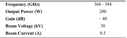
TARGETGOALS FORGYRO-TWA PERFORMANCE
components designed for the gyro-BWO. A schematic of the gyro-TWA is shown in Fig. 1.
A gyro-TWA operated at a center frequency of 372 GHz is being developed for the applications of electron paramagnetic resonance (EPR) and dynamic nuclear polarization (DNP) in a nuclear magnetic resonance (NMR) system. High-power (hundreds of watts) wide bandwidth (10%) gyroamplifiers are ideal for pulsed EPR and DNP-NMR applications. A list of tar-geted performance characteristics of the 372-GHz gyro-TWA is presented in Table I.
A well-designed coupler topology can be utilized as a method of coupling power into the interaction cavity and/or as a method of radially extracting the generated EM radiation [8]. However, higher than expected reflections from the component can result in stimulated oscillations in the cavity and loss of the amplification characteristics. The design of the input coupler is centered on the optimization of two parameters:
1) the transmission ratio from the input mode to the desired cavity mode;
2) bandwidth of the passive structure.
The potential application of the input coupler designs will be based on achieving a transmission of larger than −1 dB in the frequency range of 360–384 GHz. The frequencies at which the transmission falls below −1 dB will determine the bandwidth of the passive component, with the percent-age bandwidth determined by the deviation about the center operating frequency. A waveguide reflector is also presented, aiming to prevent the propagation of incident radiation to the electron gun, while maximizing the beam tunnel diameter.
II. T-JUNCTIONINPUTCOUPLER WITHBRAGGREFLECTOR
The proposed millimeter-wave coupler design is based upon a rectangular-to-circular T-junction. The waveguide T-junction transition has many practical applications, includ-ing the structures use as a filter [9], a polarizer [10], and in orthomode transducers [11]. Analytical methods can be used in the optimization of a simple microwave structure, also providing higher order mode information. Several ana-lytical techniques for understanding a rectangular-to-circular T-junction have been demonstrated using Fourier transform and/or mode matching techniques [12].
The rectangular-to-circular T-junction has three parameters available for optimization, which will affect the coupling of the structure. The parameters in question are the rectangular waveguide width and height, a and b respectively, and the radius of the circular waveguide, R. Efficient coupling of the TE10R mode to TEC11is achieved when the wavelength of the incident wave is approximately unchanged when transmitted into the beam tunnel, i.e., whenλgR ≈λCg, where the R and C superscripts denote the guide wavelength in the rectangular and circular waveguides, respectively.
For a gyro-TWA system, practical design limitations are often imposed on the magnitude of R, the radius of the beam tunnel. For the gyro-TWA operated at the center frequency of 372 GHz, the beam tunnel radius is 0.35 mm. In practice, the beam tunnel radius is chosen to allow for transmission of the desired mode to the interaction cavity and is made large enough to allow for unhindered electron beam propagation. The cusp electron gun for the high-frequency gyro-TWA pro-duces an electron beam of 0.2 mm in radius. The parameters a and b were numerically optimized using Computer Simulation Technology (CST) Microwave Studio (CST-MS) to minimize reflections at the input port with the optimized values of 0.55 and 0.50 mm, respectively.
[image:2.612.313.561.193.281.2]The input coupler design requires the majority of the input radiation to be transmitted to the interaction region. To prevent wave propagation into the diode region of
Fig. 2. Side view of T-junction coupler with Bragg reflector. TABLE II
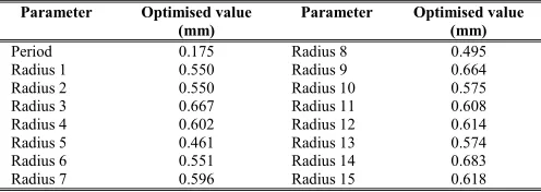
PARAMETERSET FOR372-GHz BRAGGREFLECTOR
the gyro-TWA, the use of a cutoff waveguide attached to a rectangular-to-circular T-junction is a general solution to improve the transmission coefficient over the operational bandwidth. For lower frequencies, the step-down waveguide reflector is a simple, practical method, which produces excel-lent results. However, at frequencies approaching the low-terahertz region, a cutoff waveguide can hinder the beam transportation through the cavity due to the reduced waveguide diameter at high frequencies. At the input coupler region of a gyro-TWA, the Larmor radius of the electron beam is large due to the small magnetic field magnitude relative to the center of the interaction region. Therefore, it is beneficial to increase the diameter of the waveguide structure within which the electron beam can propagate, while ensuring a high reflectivity of incident radiation.
A Bragg reflector [13] is a waveguide structure with radial periodicity, which can be used as a method of providing frequency selective feedback. A review of a Bragg reflector design in the W -band is presented in [14]. The design process was applied and an optimized reflection of ∼100% in the desired frequency band was achieved for the condition that the radii of the reflector sections are larger than R (Fig. 2). The radii of the individual sections of the Bragg reflector, listed sequentially from the section closest to the input coupler, are shown in Table II.
Fig. 3. Scattering parameters of a TE10–TE11T-junction coupler with Bragg
[image:3.612.53.297.53.219.2]reflector.
Fig. 4. L variation effect on T-junction coupler frequency response.
Transmission loss of larger than −1 dB was achieved over a∼10% bandwidth, which includes the operational frequency range of the low-terahertz gyro-TWA. A coupler of similar topology has been shown to achieve a bandwidth of 20% [15]; however, this design would only be applicable to a structure where a small diameter waveguide reflector, in comparison to the operating wavelength, is permissible. The Bragg reflector was effective in preventing the transmission of significant levels of radiation toward the electron gun with S31 of less than−15 dB achieved over the desired bandwidth.
The T-junction coupler topology displayed a degree of frequency tunability with a variation of the waveguide length between the Bragg reflector and the near edge of the input rectangular waveguide (L). The change in transmission fre-quencies is shown in Fig. 4 for variations in length L for the fixed values of a, b, and R. The frequency shifts exhibited are a result of reflected wave phase changes from the Bragg structure caused by changes in waveguide length. An increase in L is shown to lower the center frequency of the T-junction coupler alongside reducing the coupling bandwidth.
[image:3.612.315.554.57.229.2]To test the feasibility of the input coupler, a tolerance study was undertaken. A review of the effect from 10 to 20 μm
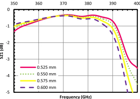
Fig. 5. Effect of small R variations on T-junction coupler transmission.
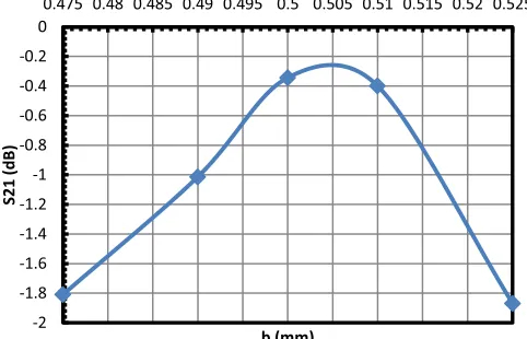
Fig. 6. Effect of a variation on T-junction coupler center frequency.
changes to R on the input coupler transmission for the fixed values of a and b is shown in Fig. 5. The resultant plot shows that small variations in the interaction waveguide radius will result in the degradation of the total coupling achieved by the waveguide structure. The spark erosion technique, which can be used to manufacture circular waveguides of submillimeter radius, can achieve a tolerance of±5μm about the optimum value. Fig. 5 suggests that a variation of 5 μm to R would ensure that high coupling to the TE11 mode is still achieved despite the radius discrepancy. A similar process involving waveguide width and height variations for fixed R was under-taken. The study highlighted that up to±25-μm variations of
a about the optimum value of 0.55 mm will result in a center
[image:3.612.53.296.268.439.2] [image:3.612.317.555.269.438.2]Fig. 7. Effect of b discrepancies on transmission at 372 GHz.
Fig. 8. Power flow of four-port directional coupler with Port 1—input, Port 2—coupled, Port 3—isolated, and Port 4—through.
III. MULTIPLE-HOLEINPUTCOUPLER
A low-terahertz, rectangular TE10 to circular TE11, multiple-hole input coupler was also evaluated through numer-ical simulations. The multiple-aperture coupler is, unlike the three-port designs described in Section II, a four-port device consisting of two transmission lines electromagnetically cou-pled through a series of common wall apertures. A commonly used power flow schematic of a four-port network is shown in Fig. 8. Directional couplers can be designed for arbitrary power division with the common coupling factors of 3, 6, 10, and 20 dB commonly employed as a method of energy extraction from a millimeter-wave cavity. The theory of small aperture coupling between transmission lines [16] provides a description of the field profile through an individual cou-pling hole. A waveguide directional coupler consists of two waveguides coupled through a series of apertures on a common broad wall [17]; however, narrow wall coupling has also been demonstrated [18]. EM coupling between rectangular and circular waveguides is also feasible [19]. The design of a rectangular-to-circular multiple-hole coupler, centered at 372 GHz, is based on achieving a high coupling factor for the desired mode and a high directivity. The coupling between the rectangular and the circular transmission lines is defined as the ratio of the power at the input port to the power at the coupled port. The directivity is the ratio of the power at the coupled port to the power at the isolated port. For an ideal multiple-aperture coupler, the directivity would be infinite. Choung et al. [20] show that the coupling (C) for a small aperture with uniform displacement as
C=
i=N i=1 aicos
2i−1 2N−1
πθC
i=N i=1 ai
(1)
Fig. 9. Coupling and directivity parameters of wanted and unwanted modes.
and, similarly, the directivity (D) as
D=
i=N i=1 aicos
2i−1 2N−1
πθD
i=N i=1 ai
(2)
whereθC andθD are the coupling and the directivity parame-ters, respectively, defined as
θC = L
2π(β1−β2) (3)
θD = L
2π(β1+β2) (4)
where L is the coupling section length. The coupling length,
L, is defined by the product of the number of apertures and the
separation between adjacent apertures (2N ∗ s). For a 30-hole
coupling section, N = 15. The phase constant,β, is unique to each of the rectangular and circular transmission lines. For a circular waveguide of R = 0.35 mm, the phase constants, β10R and β11C, are matched when a ≈ 0.60 mm. The separation between neighboring holes is equated as half the radiation wavelength (s = 0.50 mm). The coupling (3) and directivity (4) parameters for TEC10 and TMC01 are plotted as a function of frequency in Fig. 9. For the analysis, β1 is the phase constant in the rectangular waveguide andβ2is the phase constant in the circular waveguide.
In order to achieve high coupling, the propagation of unwanted modes must also be considered. For the TE11mode coupler, the three subsequent higher order modes (TM01, TE21, and TE01) are also evaluated. The only unwanted mode that will propagate is TMC01. Therefore, the coupler design should ensure that the TM01 mode has a lower coupling parameter than the TE11 mode.
Fig. 9 shows that strong coupling to the TEC11 mode is achieved, while coupling to the TMC01mode is weak compared with the desired mode. Maximum coupling is achieved for a coupling parameter equal to 0 dB. The directivity parameter of the TE11 mode is less thanθD for the TM01 mode over the entire frequency range; hence, TM01 is isolated. Therefore, the TE11 mode would be dominant at the coupled port of the four-port network.
[image:4.612.52.296.244.328.2]Fig. 10. Simulated transmission of 12-, 18-, 24-, and 30-aperture couplers.
Fig. 11. 3-D multihole geometry (L) and microwave field progression (R).
the coupling parameter (θC) and the coupling strength (ai) are constant. Equation (1) suggests strong coupling for
N=12−30. A coupling aperture radii array can improve the coupling and directivity [21]; however, a distributive array will enhance the manufacturing complexity, especially the aperture size is small at high operating frequencies. Therefore, a linear aperture distribution is employed. A numerical simulation is carried out in a bid to analyze the TE10R–TEC11transmission for 12-, 18-, 24-, and 30-hole couplers (see Fig. 10) for optimized hole radii.
Fig. 10 has indicated that the transmission from Fig. 9 for the multiple-aperture coupler is comparable with the theoret-ical prediction. However, a similar level of coupling can be achieved for 18-, 24-, and 30-aperture couplers provided the hole radius, R, is optimized. For 18 apertures, R=0.17 mm whereas 24- and 30-aperture couplers are optimized with
R =0.16 and 0.15 mm, respectively. The coupling strength
achieved with 12 apertures is less than the 18-, 24-, and 30-aperture couplers; however, the magnitude of the coupling strength is larger than −1 dB meaning it is within the target boundaries set for the input coupler design. For all four structures, the separation between Lines 1 and 2 is 0.05 mm. The desired coupling response over the required bandwidth can be achieved with 12 apertures. Therefore, subsequent designs will use 12 coupling holes (Fig. 11).
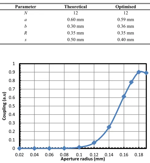
The dimensions of the theoretically calculated parameters are shown in Table III. The waveguide height (b) to waveguide width (a) ratio is initially set at 2:1. Optimization of the
TABLE III
THEORETICAL ANDOPTIMIZEDPARAMETERSET
Fig. 12. Transmission variation as effected by aperture radius at 372 GHz.
Fig. 13. Transmission variation with increase in aperture height at 372 GHz. transmission and reflection within the coupling structure is carried out through parametric sweeps of the waveguide width and height (a and b), the radius of the coupling apertures (R), and the spacing between Lines 1 and 2, i.e., the aperture height. It is known that the spacing between the center of adjacent coupling apertures (s) is∼0.4 mm; however, the R value can be set for optimum performance within the upper limit of s/2. The effect of R variation on the TER
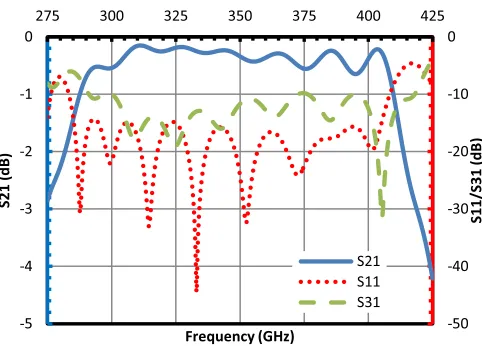
[image:5.612.315.558.386.550.2]Fig. 14. Transmission and reflection of 372-GHz 12-hole input coupler.
Fig. 12 shows that coupling to the desired mode is enhanced with increasing R up to 0.18 mm. The upper limit of 0.19 mm is dictated by the optimal pitch between the centers of adjacent apertures (0.4 mm), allowing space for machining of adjacent holes. The effect of increasing separation between Lines 1 and 2 is shown in Fig. 13, where a decrease in energy delivered to the coupled port is evident with increased separation. A metal thickness of 0.05 mm would be chosen for a manufactured multiple-hole coupler. A sheet thickness of this magnitude would allow for a high transmission to the TEC11 mode, while ensuring that a high mechanical stability is achieved in the gap spacing. The CST-MS simulated scattering of the optimized 12-aperture coupler is shown in Fig. 14.
Fig. 14 shows that an operational frequency range of 121 GHz, equating to a bandwidth of over 35%, is achieved with the 12-aperture coupler. Fig. 10, however, shows that marginal increases in coupling strength can be achieved by increasing the aperture number but additional length will lead to higher losses in the waveguide structure. The fre-quency range of the proposed fundamental mode gyro-TWA (360–384 GHz) is enclosed within the operational bandwidth of the 12-aperture input coupler and, therefore, is suitable for the proposed application. The optimized parameter set is doc-umented in Table III, showing that the theoretically calculated set provided a good basis upon which to explore the coupler design. The optimized structure has a waveguide height (b) of 0.36 mm, minimizing the reflections at the input port.
Due to the coupler operation at low-terahertz frequencies, the dimensional tolerances on certain structural parameters of the multiple-hole waveguide coupler are very sensitive. The input waveguide (Line 1) will be considered. The height of the input guide affects the coupling to the TEC11 mode in Line 2; however, the effect of b variations between 0.30- and 0.50-mm inclusive is minimal to the overall coupling strength. Therefore, a larger tolerance can be applied to the b dimension in the manufacture of the waveguide coupler. However, the feasibility study highlighted a ∼20% reduction in the power coupled to Port 2 with a 40-μm deviation from the optimum value of a. A ±10-μm variation to the waveguide width, the typical tolerance of a state-of-the-art CNC mill, would ensure that the coupling coefficient is acceptable for the gyro-TWA.
Therefore, it is permissible to construct the 12-aperture coupler with modern numerically controlled manufacturing techniques. The waveguide line sheet separation of 0.05-mm thickness will allow the microhole drilling technique to be used in the manufacture [22]. The drilling process can micro-machine apertures with a minimum diameter of 0.05 mm and an aspect ratio of 7:1 in reference to the length of aperture required to the diameter of the drill bit. Therefore, a hole of length 0.05 mm and R=0.18 mm, values used in the multiple-hole coupler simulation, is achievable.
IV. CONCLUSION ANDDISCUSSION
The design of two fundamental mode rectangular-to-circular input couplers has been presented. The design of the T-junction coupler and the multiple-aperture coupler has focused on achieving a high coupling factor from the TER10 mode to the TEC11 mode over a broad bandwidth. The use of a Bragg reflector has proved to be an effective method of providing frequency selective feedback of EM radiation at high frequency.
The operational frequency range of transmission for the T-junction input coupler is shown to be 352–390 GHz, equating to a bandwidth of ∼10%. The bandwidth of the T-junction design is limited because the required beam input port diameter is relatively large compared with the wavelength. The bandwidth of the multihole coupler is 35% (289–410 GHz). The coupler exceeds the bandwidth exhibited by the arm coupler of [19]. The use of a multiple-aperture directional coupler means that the requirement for a frequency selective wave reflector is eliminated. The 12-hole coupler design has<10% of the incident radiation propagated to Port 3.
Ohmic losses are not included in the simulations with a perfect electrical conductor background employed. However, at 372 GHz, the skin depth is∼0.1μm, which is comparable with, or smaller than, the surface roughness. This will result in increased ohmic loss. The effect of the surface roughness and skin depth can be analytically evaluated with a reduced electrical conductivity background material in CST-MS. While there is no comprehensive measured conductivity as a function of the surface roughness published at the operating frequency, an arbitrary reduction factor of 12 was used to monitor the potential losses within the designed couplers. The simulated waveguide losses for the T-junction coupler are 0.25 and 0.42 dB for the multiaperture coupler at 372 GHz with a respective corresponding bandwidth of 8% (357–387 GHz) and 28% (301–399 GHz). Coupling degradation of this mag-nitude would not pose a significant problem to either input coupler operation.
components will present a significant challenge. However, due to the large coupling bandwidth, which results in the coupler performance being less sensitive to operational frequency shifts, it is proposed a 0-dB 12-aperture directional coupler would be used for a fundamental mode input coupler on a 372-GHz gyro-TWA.
REFERENCES
[1] K. R. Chu, “The electron cyclotron maser,” Rev. Modern Phys., vol. 76, no. 2, pp. 489–540, May 2004.
[2] T. C. Luce, “Applications of high-power millimeter waves in fusion energy research,” IEEE Trans. Plasma Sci., vol. 30, no. 3, pp. 734–754, Jun. 2002.
[3] M. E. MacDonald, J. P. Anderson, R. K. Lee, D. A. Gordon, and G. N. McGrew, “The HUSIR W-band transmitter,” Lincoln Lab. J., vol. 21, no. 1, pp. 106–114, Jan. 2014.
[4] M. Y. Glyavin et al., “Experimental tests of a 263 GHz gyrotron for spectroscopic applications and diagnostics of various media,” Rev. Sci. Instrum., vol. 86, no. 5, p. 054705, 2015.
[5] G. G. Denisov et al., “Gyrotron traveling wave amplifier with a helical interaction waveguide,” Phys. Rev. Lett., vol. 81, no. 25, pp. 5680–5683, 1998.
[6] G. G. Denisov, V. L. Bratman, A. Phelps, and S. V. Samsonov, “Gyro-TWT with a helical operating waveguide: New possibilities to enhance efficiency and frequency bandwidth,” IEEE Trans. Plasma Sci., vol. 26, no. 3, pp. 508–518, Jun. 1998.
[7] W. He, C. R. Donaldson, L. Zhang, K. Ronald, P. McElhinney, and A. W. Cross, “High power wideband gyrotron backward wave oscillator operating towards the terahertz region,” Phys. Rev. Lett., vol. 110, p. 165101, Apr. 2013.
[8] G. G. Denisov, S. V. Samsonov, S. V. Mishakin, and A. A. Bogdashov, “Microwave system for feeding and extracting power to and from a gyrotron traveling-wave tube through one window,” IEEE Electron Device Lett., vol. 35, no. 7, pp. 789–791, Jul. 2014.
[9] K.-L. Wu, M. Yu, and A. Sivadas, “Novel modal analysis of a circular-to-rectangular waveguide T-junction and its application to design of circular waveguide dual-mode filters,” IEEE Trans. Microw. Theory Techn., vol. 50, no. 2, pp. 465–473, Feb. 2002.
[10] N. Yoneda, M. Miyazaki, H. Matsumura, and M. Yamato, “A design of novel grooved circular waveguide polarizers,” IEEE Trans. Microw. Theory Techn., vol. 48, no. 12, pp. 2446–2452, Dec. 2000.
[11] G. Chattopadhyay, B. Philhour, J. E. Carlstrom, S. Church, A. Lange, and J. Zmuidzinas, “A 96-GHz ortho-mode transducer for the Polatron,” IEEE Microw. Guided Wave Lett., vol. 8, no. 12, pp. 421–423, Dec. 1998.
[12] N. Yoneda, M. Miyasaki, T. Nishino, H. Asao, H. Nakaguro, and S.-I. Betsudan, “Analysis of circular-to-rectangular waveguide T-junction using mode-matching technique,” Electron. Commun. Jpn. II, Electron., vol. 80, no. 7, pp. 37–46, Jul. 1997.
[13] C. K. Chong et al., “Bragg reflectors,” IEEE Trans. Plasma Sci., vol. 20, no. 3, pp. 393–402, Jun. 1992.
[14] L. Zhang, W. He, C. R. Donaldson, J. R. Garner, P. McElhinney, and A. W. Cross, “Design and measurement of a broadband sidewall coupler for a W-band gyro-TWA,” IEEE Trans. Microw. Theory Techn., vol. 63, no. 10, pp. 3183–3190, Oct. 2015.
[15] V. L. Bratman et al., “High-gain wide-band gyrotron traveling wave amplifier with a helically corrugated waveguide,” Phys. Rev. Lett., vol. 84, no. 12, pp. 2746–2749, 2000.
[16] H. A. Bethe, “Theory of diffraction by small holes,” Phys. Rev. Lett., vol. 66, nos. 7–8, pp. 163–182, Oct. 1944.
[17] W. Shelton, “Compact multi-hole waveguide directional couplers,” Microw. J., vol. 4, no. 2, p. 89, Jul. 1961.
[18] H. Schmiedel and F. Arndt, “Field theory design of rectangular waveguide multiple-slot narrow-wall couplers,” IEEE Trans. Microw. Theory Techn., vol. 34, no. 7, pp. 791–798, Jul. 1986.
[19] W. X. Wang, W. Lawson, and V. L. Granatstein, “The design of a mode selective directional coupler for a high power gyroklystron,” Int. J. Electron., vol. 65, no. 3, pp. 705–716, Mar. 1988.
[20] Y. H. Choung, K. R. Goudey, and L. G. Bryans, “Theory and design of a Ku-band TE21-mode coupler,” IEEE Trans. Microw. Theory Techn.,
vol. 30, no. 11, pp. 1862–1866, Nov. 1982.
[21] J. Ruiz, W. Kasparek, C. Lechte, B. Plaum, and H. Idei, “Numerical and experimental investigation of a 5-port mitre-bend directional coupler for mode analysis in corrugated waveguides,” J. Infr. Millim. Terahertz Waves, vol. 33, no. 5, pp. 491–504, May 2012.
[22] (Apr. 30, 2015). Microdrilling. [Online]. Available: www.microdrilling.co.uk
Jason R. Garner received the B.Sc. (Hons.) degree in physics and the M.Sc. degree in high-power radio frequency science and engineering from the University of Strathclyde, Glasgow, U.K., in 2010 and 2012, respectively, where he is currently pursuing the Ph.D. degree with the Scottish University Physics Alliance.
His current research interests include the design of passive components for millimeter-wave gyro-amplifiers.
Liang Zhang received the B.Sc. degree in applied physics from the University of Science and Tech-nology of China, Hefei, China, in 2004, the M.Sc. degree in application of nuclear techniques from the China Academy of Engineering Physics, Mianyang, China, in 2007, and the Ph.D. degree in physics from the University of Strathclyde, Glasgow, U.K., in 2012.
He is currently with the Scottish Universities Physics Alliance, University of Strathclyde.
Craig R. Donaldson received the B.Sc. (Hons.) degree in physics and the M.Sc. degree in high-power RF and the Ph.D. degree from the University of Strathclyde, Glasgow, U.K., in 2005, 2006, and 2009, respectively.
He has since continued as a Research Fellow with the Department of Physics, University of Strathclyde. His current research interests include high-frequency gyrotron traveling-wave amplifiers/backward-wave oscillators and electron beam generation.
Adrian W. Cross received the B.Sc. degree in physics and the Ph.D. degree from the University of Strathclyde, Glasgow, U.K., in 1989 and 1993, respectively.
He joined the Atoms, Beams, and Plasmas Group, University of Strathclyde, initially as a Research Fellow. He became a Professor with the Department of Physics, University of Strathclyde, in 2014. His current research interests include terahertz radiation sources.
Wenlong He received the B.Sc. degree in physics from Soochow University, Suzhou, China, in 1983, the M.Sc. degree in accelerator physics from the China Academy of Engineering Physics, Mianyang, China, in 1988, and the Ph.D. degree in physics from the University of Strathclyde, Glasgow, U.K., in 1995.