This paper is a postprint of a paper submitted to and accepted for publication in IET Microwaves, Antennas & Propagation and is subject to Institution of Engineering and Technology Copyright. The copy of record is available at IET Digital Library.
A MICROWAVE COUPLER FOR W-BAND MICRO RE-ENTRANT
SQUARE CAVITIES
Claudio Paoloni
Lancaster University, Engineering Department Lancaster, LA1 4YW, UK
Mauro Mineo
e2v Technologies, Chelmsford, CM1 2QU, UK
Huabi Yin, Liang Zhang, Wenlong He, Craig W. Robertson, Kevin Ronald, Alan D. R. Phelps and Adrian W. Cross
University of Strathclyde, Department of Physics, SUPA 107 Rottenrow, Glasgow, G4 0NG, UK
Abstract – Klystrons are vacuum electronic devices widely used for microwave amplification up to the millimetre-wave region. The opportunity to push the operating frequency of conventional klystrons above 30 - 40 GHz is limited by the fabrication difficulties of the cavities that have very small dimensions. A high order mode micro re- entrant square cavity was purposely devised to be compatible with the available micro fabrication processes and represents a viable solution for the design of millimetre-wave klystrons. In this paper, a coupler to correctly excite the higher order mode of the square re- entrant cavities for W-band operation is proposed. The design of the proposed novel coupler structure has been validated by realization and measurement of a scaled X-band prototype. The post-realization tuning methods adopted to improve the matching of the high order mode are also presented.
1.
INTRODUCTION
Vacuum electron devices are the most viable solution to generate and amplify microwave signals at high power levels. The klystron is a well-known high-efficiency vacuum amplifier with excellent control of the phase and amplification gain. It has been widely used in many applications, such as radar, particle accelerators, radiotherapy and so on, for the frequency range up to the W-band and above [1]–[3]. The operating principle of the klystron is based on the velocity modulation of the electron beam by the excited electric field at the input cavity. The modulated electron beam is then bunched along the drift tube, and finally its energy is transferred to the electromagnetic field at the output cavity.
Unconventional klystron configurations, such as extended interaction klystrons (EIKs) [2] and sheet beam klystrons [3], have been demonstrated to be effective in the millimetre-wave band. In the W-band, the EIK is able to achieve a pulsed power of 3 kW and average power of 400 W at the frequency of 95 GHz. Nonetheless, the realization of such unconventional klystron devices requires extremely demanding technological efforts.
geometrical dimensions makes the design and realization of the couplers for millimetre-wave cavities an extremely challenging task and novel configurations have to be adopted.
The use of a high order mode in a cavity permits wider dimensions for a given operating frequency, thus relaxing the fabrication process. This is particularly relevant when the operating frequency approaches the mm-wave region and fabrication processes such as LIGA (German acronym for lithography, electroplating and molding) [4] and micro mechanical milling [5] must be adopted.
The micro re-entrant square cavity [6] was demonstrated as a promising solution for the design of klystrons at mm-wave frequencies. It supports a high order mode with an electric field distribution on the cavity gap similar to the one of the fundamental mode. Moreover, its geometry is suitable to be realized by multi-layer micro-fabrication processes and, at the same time, to interact effectively with a cylindrical beam [7].
A RF coupler for the excitation of the high order mode to support beam-wave interaction in mm-wave micro re-entrant square cavities was proposed in [8]. In this paper,the properties of the coupler wereverified by measurements of a scaled prototype operating in theX-band, and the post-realization tuning technique, used to improve the matching of the high order mode, is verified in the measurement and analysed in detail.
2.
DESIGN OF THE W- BAND COUPLER
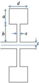
The correct excitation of a high order mode in a cavity requires a proper coupling approach depending on the distribution of the electric field. The small dimensions at W-band impose tight fabrication and assembly constraints that only a purposely designed topology can satisfy. The re-entrant cavity schematic is shown in Fig. 1. The dimensions for W-band operation are listed in Table 1.
Parameter Value (mm)
a 1.1
b 1.3
c 0.2
s 0.2
[image:2.595.275.343.458.601.2]d 1.4
[image:2.595.197.398.631.751.2]Table 1. Geometrical dimensions of the W-band cavity
A microwave coupler for W-band micro re-entrant square cavities 3
The eigenmode analysis of the resonant modes showed that the 5th mode has the required field distribution that has maximum field strength around the beam tube, as shown in Fig. 2. With the dimensions in Table 1, the resonance frequency of the fundamental mode is 20.75GHz and the 5th mode is 104.1 GHz. Therefore, the dimensions of the high order mode cavity are about five times larger than the corresponding cavity operating at the fundamental mode.
The RF coupling of overmoded cavities is generally a challenging task, since the coupler must ensure proper isolation with undesired or degenerate resonant modes and offer suitable values of R/Q at the same time. For mm-waves the design of the RF coupler is even more challenging, since the cavity must be fed through a rectangular waveguide flange and the whole structure must comply with the micro-fabrication process to be used in its construction.
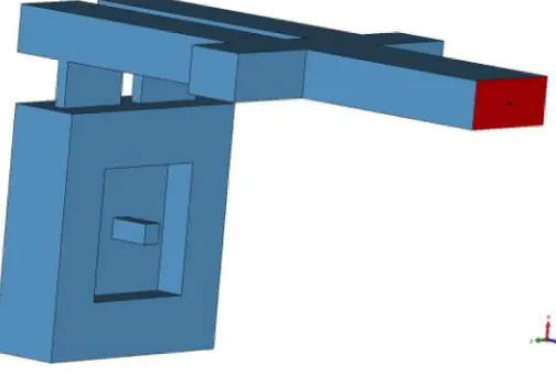
In order to excite efficiently the 5th mode, its electric field distribution was considered. As shown in Fig. 2, the field displays four lobes and two of them can be coupled to the modes of two rectangular waveguides through two coupling apertures. Apertures are needed on the cavity surface to couple the resonant mode with an external microwave circuit. The proposed coupler geometry is depicted in Fig. 3. Two coupling apertures have been placed on one side of the cavity, to coincide with the lobes (Fig. 2b) of the considered resonant mode. Two rectangular waveguides were connected to the coupling apertures in the cavity. The matching between the coupling apertures and the waveguides has been achieved by a power splitter/combiner. A central T-junction acts as a balanced power splitter/combiner. The two branches of the T-junction feed/collect the z-component of electric field in the cavity by the
[image:3.595.125.475.237.377.2](a) (b)
Figure 2. Amplitude of the longitudinal component of the electric field on the transverse section of a micro re-entrant square cavity: (a) fundamental mode (20.75 GHz); (b) fifth mode (104.1 GHz).
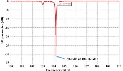
[image:3.595.178.430.431.601.2]feeding-slots. A rectangular waveguide flange is connected to the two waveguide branches. It also serves as the solo input/output port of the whole structure, shown as port 1 in Fig. 3. In order to enhance the coupling, the end of the two power splitter branches are provided with short circuits. In addition, two stubs were added in the T-junction to improve the input/output matching. Such a coupler geometry complies with the micro-fabrication processes discussed in the introduction. The schematic of the coupler is shown in Fig. 4. The dimensions at W-band for an operating frequency of 104 GHz are listed in Table 2. The scattering parameter of the coupler was simulated by CST Microwave Studio [9] with the frequency domain solver. In the simulation, a tetrahedral mesh type was chosen and the adaptive mesh refinement was used until the result is convergence. The reflection result is shown in Fig. 5 and the minimum reflection is about -30 dB at 104.16 GHz.
Figure 5. Simulation of the coupler. The S11 is about -30.9 dB at 104.16 GHz.
3.
SIMULATION AND TEST OF THE COUPLER
The proposed W-band coupler has been validated by realization and measurements of an X-band scaled version of the W-X-band cavity with the coupler. The dimensions of the previously described structure have been scaled to obtain the high order mode resonating at 9.57 GHz. Since the structure is passive, all the results obtained for the X-band model can be projected to the mm-wave range by scaling the dimensions as a function of the given frequency.
[image:4.595.173.434.482.633.2]A microwave coupler for W-band micro re-entrant square cavities 5
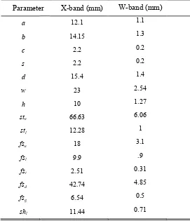
The geometry of the coupler has been slightly optimised after the dimension scaling by CST Microwave Studio imposing a reflection of the port 1 |S11| < -20 dB at the resonance frequency as the optimization goal. The input port was an X-band WR-90 waveguide that allows it to be easily connected to a vector network analyzer (VNA) for measurement with the aluminium structure. The dimensions of the optimized structure of the machined and measured X-band coupler are reported in Table 2 along with the dimensions of a W band coupler.
Parameter X-band (mm) W-band (mm)
a 12.1 1.1
b 14.15 1.3
c 2.2 0.2
s 2.2 0.2
d 15.4 1.4
w 23 2.54
h 10 1.27
stw 66.63 6.06
stl 12.28 1
fsw 18 3.1
fsl 9.9 .9
fst 2.51 0.31
fsd 42.74 4.85
fsg 6.54 0.5
[image:5.595.162.433.178.493.2]shl 11.44 0.71
Table 2. Geometrical dimensions of theW-band and X-band cavities and couplers
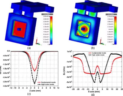
The coupler exhibits a|S11| well below -20 dB at the resonant frequency in the simulation. The effectiveness of the coupler to excite the 9.57 GHz higher order mode is highlighted in Fig. 6. Note that both the correct propagation of the TE10 mode along the coupler (Fig. 6a) and the required 5th mode field distribution (Fig. 6b) were achieved.
(a) (b)
Figure 6. Detail of the electric field distribution in the coupler (a) and in the cavity (b) when the cavity is fed through the waveguide port.
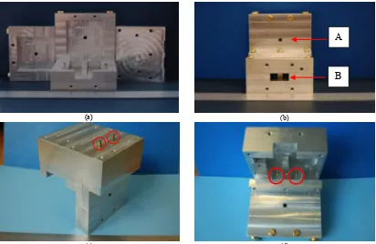
The X-band model of the cavity with the coupler was realized through computer numerical control (CNC) milling of 4 separate pieces. The process assures a surface roughness lower than 250 nm and a tolerance of ±10 µm. A tolerance of +10 µm with respect to the nominal dimensions was achieved. The cavity and the coupler can be formed by assembling all the pieces together by screws. The photos of the realized pieces and the structure after assembly are shown in Figures 8(a) and (b). The smaller aperture marked as A in Fig. 8(b) is the drift tube and the bigger one marked as B is a WR-90 waveguide port.
(a) (b)
(c) (d)
Figure 7. (a) Fundamental and (b) fifth modes of the cavity with the RF coupler: electric field distribution at the resonant frequency; (c) comparison of the Ez field component along the beam
[image:6.595.104.518.277.599.2]A microwave coupler for W-band micro re-entrant square cavities 7
The X-band prototype of the coupler has been tested using a VNA. The VNA was calibrated by the two-port Short-Short-Load-Thru (SSLT) method and the reflection was measured through the single port with the WR-90 flange. The results of the measurements are compared with those of the simulations in Fig. 9. A small shift in the resonant frequency between the simulation and the measurement was found in the resonant frequency in the higher order mode. This may be due to either the mesh resolution in the CST simulation or geometric issues of the cavity itself during assembly, such as the screws that hold the aluminium structure together being a little misaligned, which would result in a slightly different dimension on the inside of the structure and therefore a small shift in the resonant frequency.
The performance of the coupler at the operating frequency can be further improved by the use of tuning posts, placed in the middle of the two branches of the power splitter and aligned with the feeding slots as shown in Fig. 10 and in the pictures in Fig. 8(c) and (d). The
(a) (b)
(c) (d)
[image:7.595.102.514.70.338.2]Figure 8. Photos of the realized X-band coupler: (a) parts before the machining for the tuning screws; (b) front view of the assembly; (c) detail of the tuning screws; (d) detail of the tuning posts inside the coupler structure.
Figure 9. Comparison between magnitudes of the measured and simulated |S11|.
A
[image:7.595.186.428.534.712.2]diameter of the tuning posts was chosen as 1.5 mm, therefore slightly smaller than the thickness of the coupling apertures (fSt = 2.51 mm).
The S11 has been measured by varying the depth of both posts identically and by varying the depth of only the left post (keeping the depth of the other post equal to 0). The comparison between the measurements and the simulation results is shown in Fig. 11. The optimum depth to obtain the minimum |S11| for the 9.57 GHz mode is 4.2 mm when the tuning is performed by both posts, and it is 4.9 mm when the tuning is performed only by the left post. The |S11| for the lower order modes remains well above -5 dB level.
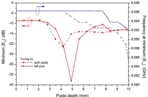
[image:8.595.199.398.105.270.2]As shown in the insets of Fig. 11, the increase of the depth of the posts produces a small shift of the resonant frequency. The matching conditions and the relative resonant frequencies as a function of the posts’ depth are reported in Fig. 12. As expected the greater the depth, the more the posts will load the cavity impedance, leading to a bigger frequency shift. When the depth is around 10 mm the posts are already in the feeding slots, and the coupler is no longer effective.
Figure 10. Detail of the coupler region with the tuning posts.
(a) (b)
[image:8.595.109.511.389.541.2]A microwave coupler for W-band micro re-entrant square cavities 9
4.
CONCLUSIONS
A novel coupler for an overmoded micro re-entrant square cavity has been presented. The geometry of the proposed coupler and the cavity are fully compatible with micromechanical manufacturing processes for millimetre-wave applications.
Simulations by the three dimensional electromagnetic simulator CST Microwave Studio demonstrated the ability of the coupler to excite the required 5th mode in the square cavity that ensures the relevant beam-wave interaction.
The performance of the coupler has been validated by experimental measurements on an X-band prototype realized by CNC milling. The experiment demonstrated a good agreement with the simulated resonant frequencies. Post-realization tuning techniques have been successfully applied to improve the matching of the 5th mode. The single post tuning ensures an optimum tuning of the coupler.
ACKNOWLEDGEMENTS
This work was funded by MIUR PRIN Project 2008, Italy, the STFC, research project ST/K002961/1, UK and the EPSRC, UK.
BIBLIOGRAPHY
[1] J. H. Booske, R. J. Dobbs, C. D. Joye, C. L. Kory, G. R. Neil, G.-S. Park, J. Park, and R. J. Temkin, “Vacuum Electronic High Power Terahertz Sources,” IEEE Trans. Terahertz Sci. Technol., vol. 1, no. 1, pp. 54–75, Sep. 2011.
[2] A. Roitman, D. Berry, and M. Hyttinen, “Sub-millimeter waves from a compact, low voltage extended interaction klystron,” in Infrared and Millimeter Waves, 2007 and the 2007 15th International Conference on Terahertz Electronics. IRMMW-THz. Joint 32nd International Conference on, 2007, pp. 4–6.
[3] Y.-M. Shin, J.-X. Wang, L. R. Barnett, and N. C. J. Luhmann, “Particle-In-Cell Simulation Analysis of a Multicavity W-Band Sheet Beam Klystron,” IEEE Trans. Electron Devices, vol. 58, no. 1, pp. 251–258, Jan. 2011.
[image:9.595.165.451.71.260.2][4] C. D. Joye, A. M. Cook, J. P. Calame, D. K. Abe, and B. Levush, “Breakthrough UV-LIGA Microfabrication of Sub-mm and THz Circuits,” in Vacuum Electronics Conference (IVEC), 2013 IEEE Fourteenth International, 2013, pp. 3–4.
[5] A. Baig, D. Gamzina, R. Barchfeld, J. Zhao, C. Domier, A. Spear, L. R. Barnett, and N. C. J. Luhmann, “220 GHz Ultra Wide band TWTA : Nano CNC Fabrication and RF testing,” in Vacuum Electronics Conference (IVEC), 2013 IEEE Fourteenth International, 2013, pp. 1–2.
[6] M. Mineo and C. Paoloni, “Micro Reentrant Cavity for 100 GHz Klystron,” in
Vacuum Electronics Conference (IVEC), 2012 IEEE Thirteenth International, 2012, pp. 65–66.
[7] C. Paoloni, “Periodically Allocated Reentrant Cavity Klystron,” IEEE Trans. Electron Devices, vol. 61, no. 6, pp. 1687–1691, Jun. 2014.
[8] C. Paoloni, M. Mineo, H. Yin, L. Zhang, W. He, C. W. Robertson, K. Ronald, A. D. R. Phelps, and A. W. Cross, “Scaled design and test of a coupler for micro-reentrant square-cavities for millimeter wave klystrons,” in 2013 IEEE 14th International Vacuum Electronics Conference (IVEC), 2013, pp. 1–2.