City, University of London Institutional Repository
Citation
:
Karathanassis, I. K., Papanicolaou, E., Belessiotis, V. and Bergeles, G. (2013). Multi-objective design optimization of a micro heat sink for ConcentratingPhotovoltaic/Thermal (CPVT) systems using a genetic algorithm. Applied Thermal Engineering, 59(1), pp. 733-744. doi: 10.1016/j.applthermaleng.2012.06.034
This is the accepted version of the paper.
This version of the publication may differ from the final published
version.
Permanent repository link:
http://openaccess.city.ac.uk/14849/Link to published version
:
http://dx.doi.org/10.1016/j.applthermaleng.2012.06.034Copyright and reuse:
City Research Online aims to make research
outputs of City, University of London available to a wider audience.
Copyright and Moral Rights remain with the author(s) and/or copyright
holders. URLs from City Research Online may be freely distributed and
linked to.
City Research Online: http://openaccess.city.ac.uk/ publications@city.ac.uk
Multi-objective Design Optimization of a Micro Heat Sink for
Concentrating Photovoltaic/Thermal (CPVT) Systems using a Genetic
Algorithm.
Ioannis K. KARATHANASSIS 1, 2, *, Elias PAPANICOLAOU 1, Vassilios BELESSIOTIS 1, Georgios C. BERGELES 2
* Corresponding author: Tel.: ++30 210 6503815; Fax: ++30 210 6544592; Email: ikarathanassis@ipta.demokritos.gr
1 Solar & other Energy Systems Laboratory, Institute of Nuclear Technology & Radiation Protection, National Centre for Scientific Research DEMOKRITOS, Greece, Email: sollab@ipta.demokritos.gr
2 Laboratory of Innovative Environmental Technologies, School of Mechanical Engineering, National Technical University of Athens, Greece, Email:
bergeles@fluid.mech.ntua.gr
Abstract An optimization methodology for a microchannel, plate-fin heat sink
suitable for the cooling of a linear parabolic trough Concentrating
Photovoltaic/Thermal (CPVT) system is applied in this study. Two different microchannel configurations are considered, Fixed (FWμ) and stepwise Variable-Width (VWμ) microchannels respectively. The performance evaluation criteria comprise the thermal resistance of the heat sink and the cooling medium pressure drop through the heat sink. Initially, the effect of the geometric parameters on the heat sink thermal and hydrodynamic performance is investigated using a thermal resistance model and analytical correlations, in order to save computational time. The results of the 1-D model enable the construction of surrogate functions for the thermal
resistance and the pressure drop of the heat sink, which are considered as the
objective functions for the multi-objective optimization through a genetic algorithm that leads to the optimal geometric parameters. In a second step, a 3-D numerical model of fluid flow and conjugate heat transfer for the optimized FWμ heat sink is developed in order to investigate in detail the flow and thermal processes. The overall analysis demonstrates that microchannel heat sinks achieve very low values of
thermal resistance and that the use of variable-width channels can significantly reduce the pressure drop of the cooling fluid. Furthermore, it is proven that the 1-D model is capable of providing a good estimate of the behavior of the heat sink.
Keywords: CPVT, Microchannel Heat Sink, Conjugate Heat Transfer, Response
surfaces, Genetic algorithm, Multi-objective optimization
Nomenclature
a wall thickness to channel width ratio, dimensionless A area, m2
AR aspect ratio, dimensionless
Ar Archimedes number 2 Re
Gr
Ar , dimensionless
cp specific heat, J/kgK
Dh hydraulic diameter
ch ch ch ch h H W H W D
f Fanning friction factor, dimensionless
Gr Grashof number
2 4 f h k D q g
Gr , dimensionless
H height, m
h heat transfer coefficient
z T z T z q z h m w , W/m2K
k thermal conductivity, W/mK L length, m
m fin parameter
w sW
k h
m 2 , m-1
N number, dimensionless
Nu Nusselt number, dimensionless P channel perimeter, m
p pressure, Pa
Ppump pumping power, W
Pr Prandtl number, dimensionless Q thermal power, W
q’’ heat flux, W/m2
Rth thermal resistance, K/W
Re Reynolds number
umDh
Re , dimensionless
T temperature, K ts substrate thickness
u flow velocity, m/s
V volumetric flow rate, m3/s
W width, m
X* non-dimensional spanwise coordinate
ch w * W W x X 2
Y* non-dimensional height-wise coordinate
ch s * H t y
Y
Z* non-dimensional streamwise coordinate
h * D Pr Re z Z
zth thermal entry length, m
Greek symbols
β volumetric thermal expansion coefficient, Κ-1 μ dynamic viscosity, Pas
Subscript
ave average c contraction cs cross-section
cal caloric conv convective cond conductive ch channel cs cross section d developing e exit
f fluid
fd fully developed hs heat sink i inlet init initial m mean
s solid, section th thermal tot total w wall
1. Introduction
Microchannel heat sinks constitute an innovative cooling technology capable of dissipating high heat fluxes from confined areas. The implementation of microchannel heat sinks was initially necessitated for the cooling of electronic integrated circuits, as the ongoing increase in circuit density and operational speed of modern electronic components also leads to increased heat generation rates that need to be efficiently dissipated. Furthermore, advances in fabrication techniques have led to electronic chips of continuously diminishing dimensions, which, as a consequence, require compact cooling systems. Microchannel schemes meet these demands as they combine high surface-to-volume ratio and large convective heat transfer coefficient [1].
Tuckerman and Pease [2] were the first to introduce the concept of liquid cooling by utilizing microchannels. They created three different heat sink configurations by chemically etching parallel channels onto silicon chips. Their experimental evaluation showed that the thermally superior configuration was able to dissipate a flux of 790 W/cm2. Harms et al. [3] conducted an analytical and experimental evaluation of laminar flow and forced convection inside a heat sink of total dimensions 2.5 cm x 2.5 cm incorporating deep microchannels with an aspect ratio (Hch/Wch) of 4.1. They pointed out that microchannels with a high aspect ratio exhibit enhanced thermal and hydrodynamic performance. Moreover, they demonstrated that the multiple-channel configuration exhibits superior thermal performance for a given pressure drop, in comparison to a single-channel heat sink designed for turbulent flow. Qu and
respectively. In both cases a periodic unit cell consisting of a single microchannel and the surrounding material was selected as the computational domain, due to the
existent symmetry. The numerical analysis demonstrated that the average temperature rise along the flow direction, in both the fluid and solid part of the heat sink can be considered as linear. The numerical procedure was validated against the experimental evaluation that was also conducted for the second heat sink configuration, as close agreement was found between the predicted values and the experimental data for the heat sink temperature distribution and pressure drop. The authors came to the
conclusion that the conventional Navier-Stokes and energy equations can accurately predict the flow and heat transfer conditions inside a microchannel heat sink. In general, the open literature is quite extensive on the subject of microchannel cooling and additional references concerning the flow and heat transfer inside microchannels can be found in review papers on high heat flux cooling technologies such as those by Agostini et al. [5] and Khandlikar & Bapat [6].
A critical stage in the heat sink design procedure is the determination of the optimal geometric parameters that maximize overall performance. A number of researchers [3, 7-11] has utilized analytical methods in order to highlight the effect of the microchannels main dimensions, such as channel width, aspect ratio and vertical wall thickness, on the heat sink thermal and hydrodynamic performance.
Multi-objective optimization techniques in combination with genetic algorithms have also been proven to be suitable solution methods for problems where multiple criteria must be satisfied, as they result to concurrent optimization of all the objectives [12]. Copiello and Fabbri [12] coupled a simplified numerical procedure with a multi-objective optimization technique in order to determine the optimal geometry of a wavy finned heat sink. They stated that the use of a detailed three-dimensional numerical model would lead to excessively time consuming computations. Husain and Kim [13] used a full three-dimensional numerical model of a parallel
microchannel heat sink, in order to produce an initial number of objective function values required for the multi-objective optimization. Ndao et al. [14] performed a comparative analysis and multi-objective optimization of various cooling technologies using genetic algorithms coupled with one-dimensional models and correlations that approximate the overall behavior of the different configurations.
Although microchannel cooling is well-suited to thermal management of electronics, its use can be extended to other technological fields where there is also demand for high heat flux dissipation. The present work investigates the applicability of microchannel heat sinks to Concentrating Photovoltaic/Thermal (CPVT) systems. Such systems utilize optical devices to concentrate solar irradiation onto a small receiver area which is occupied by highly efficient solar cells. The presence of a high heat flux can cause excess increase on the solar cell temperature, which leads to efficiency loss and long-term degradation. Therefore, the incorporation of an efficient and compact heat sink is vital, so as to maintain the operating cell temperature within allowable ranges and moreover to extract surplus heat, which can be exploited in other applications. More specifically, this study focuses on the cooling of a linear parabolic trough CPVT system using two microchannel configurations employing fixed- and variable-width microchannels respectively. A complete methodology for the heat sink geometry optimization is presented. Initially, a one-dimensional thermal resistance model and pressure drop correlations are utilized, in order to approximate the overall performance of each configuration. In a second step, the objective
to perform the multi-objective geometrical optimization, which constitutes the final step of the method. In addition, a three-dimensional numerical model of the optimal FW configuration is developed to further illustrate the features of the flow and temperature fields inside the heat sink.
2. Heat Sink Configurations
The microchannel heat sink is bonded to the backside of a solar cell module (Fig. 1) on the front side of which, a constant flux of concentrated solar radiation is incident. A percentage of the incoming irradiation, in the order of 15-20%, is absorbed by the PV module and directly converted to electricity. The remaining energy is converted into heat to be extracted by the heat sink, which is made of aluminum, due to the high thermal conductivity of the material (kal=237W/mK). The total area of the
microchannel heat sink, corresponding to the area of the CPVT system receiver, is 0.5 x 0.06m2. The parabolic reflector aperture is equal to 1 m2 so that a constant flux of 33kW/m2 is incident on the PV surface. Water was chosen as the cooling medium with a total volumetric flow rate of 30ml/s, which is sufficient for a system producing hot water at 60oC for domestic use. The cooling fluid, after entering the heat sink
through an inlet nozzle, branches into N parallel microchannels. The flow inside each microchannel is characterized by the Reynolds number based on the flow mean velocity um, which is defined as:
cs , ch tot m A N V u
(1)
where Vtot and Ach,cs are the total volumetric flow rate of the cooling fluid and the cross-sectional area of the microchannel respectively.
3. 1-D Analysis
3.1 Fixed-width microchannels (FWμ)
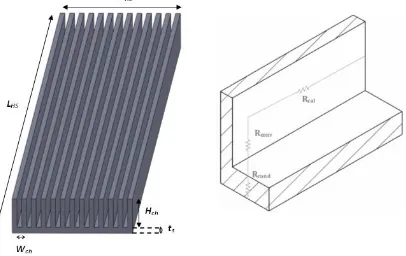
The overall performance of the microchannel heat sink (Fig. 2a) was predicted by means of a one-dimensional thermal resistance model (Fig. 2b) and pressure drop correlations. The thermal resistance model has been reported as adequate to fully represent the thermal performance of a heat-sink configuration [10] and furthermore its simplicity makes it suitable for optimization purposes [3,15].The total thermal resistance of the heat sink is [16]:
conv cal
cond
tot R R R
R (2)
The conductive and caloric thermal resistances are:
A k t R s s cond p tot cal c V R
1 (3)
conductive thermal resistance is independent from the design and operating parameters of the heat sink; instead it is fully determined by a techno-economic constraint such as the substrate minimum thickness. Besides, for a substrate thickness easily attainable with conventional machining processes, the use of a thermally conductive substrate material (such as aluminum or copper) would limit the
magnitude of the conductive thermal resistance to approximately 1-2% of the total, for a heat sink of similar overall dimensions to the one investigated. The convective thermal resistance is given by:
N H W L
h A h R ch ch fin
conv
2 1 1
(4)
where Wch and Hch are the microchannel width and height respectively. The overall heat transfer coefficient h is considered as the average over the channel base and vertical walls, with the top being adiabatic, and the corresponding Nusselt number value, is taken constant for a given geometry and can be easily obtained from analytical correlations or tabulated values [17]. The side walls of the microchannels are thought of as fins with efficiency:
ch ch fin mH mH tanh (5)
where m is the fin parameter. An equivalent definition for the total thermal resistance (neglecting the conductive thermal resistance) is [10]:
Q T T
Rth w,max f,i (6)
where Tw,max, Tf,iand Q are the microchannel bottom wall maximum temperature, the cooling fluid inlet temperature and the thermal power at the heat sink bottom surface respectively.
The hydrodynamic performance of the heat sink is described by the total pressure drop of the cooling fluid:
e fd d
c
tot p p p p
p
(7)
The four terms on the right-hand side of Eq. (7) refer to the pressure drop in the entrance, the developing flow region, the fully-developed region and the exit of the microchannel respectively, where the last term is negligibly small. The pressure drop due to contraction can be calculated from an analytical correlation given by Blevins
[18] and accounts for the additional pressure losses due to flow impingement on the
fins (walls) leading surfaces and consequent separation downstream of the fin edge. The pressure drop in the developing and the fully-developed region is expressed by a relation of the general form:
h m d D u fL p 2 2
where Ldis the length of the entrance region (or development length), correlations for which are given by Shah and Bhatti [19], or the length of the fully-developed region respectively, and f should be substituted by the apparent Fanning friction factor in the developing region [20] or accordingly by the Fanning friction factor for
fully-developed flow [9,17]. For very small hydraulic diameters, as in the case of microchannels, where the hydrodynamic entry length is also small, the overall pressure drop through the heat sink is predominantly influenced by the fluid friction to the channel walls.
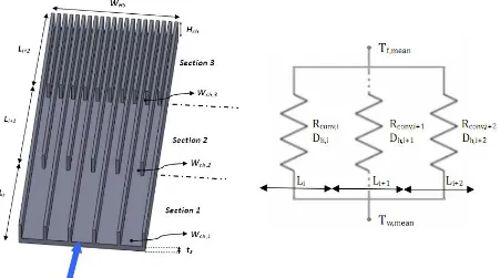
3.2 Variable-width microchannels (VWμ)
The concept of the stepwise variable-width (VW) microchannel heat sink (Fig. 3a) is based on two basic remarks. On one hand, by reducing the channel width, while maintaining the height constant, the Nusselt number increases [17] and so does also the total heat transfer coefficient, being further enhanced by the reduction of the hydraulic diameter. On the other hand, upon reduction of the hydraulic diameter the Fanning friction factor and thus the pressure drop also, increases.
In the case of a microchannel heat sink of constant hydraulic diameter which receives a uniform heat flux, the bottom wall and the bulk fluid temperature both increase in a similar linear fashion, when the flow becomes fully developed [21]. The only option for enhancing the temperature uniformity of the bottom wall is therefore to gradually increase the heat transfer coefficient along the direction of the flow by adding more heat transfer surfaces [22]. Additionally, using wider channels in the first section of the heat sink, where the bulk fluid temperature is low, decreases the overall pressure drop compared to a heat sink with the narrower channels throughout.
In order for such a heat sink to be structurally feasible, the width of the channel along consecutive sections must be decreased in the following manner:
2 2 w upstream , ch downstream , ch W W
W (9)
The total thermal resistance of the VWμ heat sink can be determined by Eq. (2), if a mean convective resistance is defined as for the case of parallel resistances:
Nsi i i
Ns
i conv,i tot
,
conv R hA
R 1 1
1 1
1
(10)
where Ns is the number of sections, taken equal to three in the present analysis. Each section of the VW heat sink is characterized by a different number Ni of
microchannels having width Wch,i and therefore, according to Eq. (4), an individual convective thermal resistance should be assigned to each one. Eq. (10) is obtained if the equivalent thermal resistance network is considered (Fig. 3b), where the thermal resistances of the equal-length sections of different hydraulic diameters should be connected in parallel, as the total heat flux at the microchannel bottom wall branches to the three sections. The total pressure drop can be obtained by adding the pressure drop values along each section as derivedbyEq. (7). It should be noted that,
should be checked so that the respective proper values for the Nusselt number and the Fanning friction factor be selected.
4. Optimization
4.1 Objective functions and design variables determination
The thermal and hydraulic behavior of the heat sink can be fully described by the sum of the convective and the caloric thermal resistance, Eq. (3), as well as the required pumping power, which is defined as:
p V
Ppump tot (11)
These two quantities are selected as the objective functions for the optimization process.
The total width and length of the microchannel heat sink are fixed and therefore the design parameters which determine the heat sink performance and can be generally included in the optimization process are the channel width Wch and aspect ratio AR=(Hch/Wch), along with the fin thickness Ww. It is evident from the analytical correlations for the thermal resistance and pressure drop that, for a constant channel width, an increase in the channel aspect ratio has a beneficial impact on both the objective functions, due to the increase of the available heat transfer area and the decrease of the flow velocity. Therefore, the height is fixed at the maximum structurally feasible value. Consequently, two independent design variables are selected for optimization, namely the microchannel width Wch and the fin thickness Ww. Provided that these design variables are determined, the total number of
microchannels can be attained as the closest integer to the value calculated from the relation: ch ch HS W ) a ( aW W N 1
, where
ch w
W W
a (12)
For the VWμ heat sink in particular, the fin thickness Ww must also be constrained by the minimum structurally feasible value. This constraint is posed by structural
limitations that dictate that the thickness of the fins through all the sections of the heat sink be maintained constant. In addition, regarding the first heat-sink section, the fin thickness cannot be a very small fraction of the channel initial width as this would lead to rupture of the fins during the machining process. The a ratio, Eq. (12),
4.2 Surrogate functions
A pair of design variables(Wch, Ww) produces an output value of both the objective functions. The response values define a surface as a function of the design variables in the three dimensional space [23] and can be adequately approximated by surrogate functions of the typez f
x,y . A number of surrogate functions were evaluated for the fitting of the analytically produced data. The adjustedcoefficient of multiple determination Radj2 was used as the evaluation criterion, which quantifies the quality of the fitting, with a value equal to unity indicating an excellent fitting. A third order polynomial was finally chosen to approximate the thermal resistance response:
3 03 2 12 2 21 3 30 2 02 11 2 20 01 10 00 w w ch w ch ch w w ch ch w ch w ch th W p W W p W W p W p W p W W p W p W p W p p W , W R (13a)Similarly, a power function was selected to approximate the pumping power response, considering the decaying trend that it exhibits:
2 31 b w b ch w ch
pumpW ,W b W W
P (13b)
Referring to the VWμ microchannels, single-variable surrogate functions are used, as the ratio of the fin thickness to the initial channel width is kept constant to 0.2. Hence, the surrogate functions reduce to the forms:
ch,init
ch,initth W r rW
R 0 1 (14a)
21 c init , ch init , ch
punpW cW
P (14b)
4.3 Multi-objective optimization using the genetic algorithm
The heat sink optimization constitutes a multi-objective optimization problem, which can be mathematically formulated as follows:
f (x),f (x),...,f (x)
) x ( f min i 2 1
(15)
0
0
and h(x) )
x ( g to
subject
wherex is the vector that contains the design variables and f(x),g(x),h(x)are the vector functions that contain the objective, inequality and equality constraints
functions respectively. The multi-objective optimization process converges to a set of non-dominated solutions, called the Pareto front [24].
successive iterations or generations. At each step, individuals of the current population are selected to produce offsprings of the next generation. The selection procedure is based on the objective function values that each individual produces, leading to the designation of a fitness scoreFi
x , which is a measure of each individual’s performance, regarding an objective function, relative to the whole population of individuals:
in d N j i i i x f x f x F 1 (16)Individuals within the generation are ranked according to their fitness score and the ones that are to participate in the creation of the next generation are determined probabilistically according to the values of their fitness score. The children of the next generation are created using three types of selection mechanisms: preservation of the individuals with the best fitness score (elite children), combination of two parent individuals (crossover children) and random changes introduced to a single individual
(mutation children) [26]. As the individuals with high fitness score are more likely to
be preserved along consecutive generations, the algorithm gradually evolves to the optimal or non-dominated solutions. An individual A (x) is characterized as a non-dominated solution when there is no other individual B, which achieves a better fitness for a single objective fi(x)
without deteriorating the other objectives. As the algorithm reaches the imposed termination criteria, the non-dominated individuals over all generations lead to the formation of the Pareto front [27].
5. Optimization Results
5.1 Validation
The results of the developed 1-D thermal resistance model for the heat transfer and the pressure drop correlations were compared against the experimental values published by Tuckerman and Pease, who investigated the performance of a silicon
(ksi=148 W/mK) microchannel heat sink of total dimensions (1 cm) x (1 cm), cooled
by water with an initial temperature of 296 K. According to Table 1, the experimental values agree well with the analytically predicted ones. The small discrepancy in the pressure drop values is due to the fact that the analytical model does not account for the pressure loss of the coolant in the inlet-outlet manifold that was used during the experiments, as reported by Tuckerman and Pease [2].
5.2 Optimal solutions
The design variables for the optimization of the present FWμ and VWμ heat sink configurations were allowed to vary within the following ranges:
m W m m W m m W m init , ch w ch 5000 1000 500 100 500 100 (17)
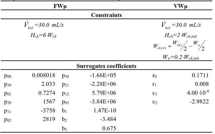
heat sink that was selected for the optimization process. The channel height is chosen to be six times the channel width in the FWμ heat sink and two times the initial channel width in the VWμ heat sink, as these are the maximum values that can be attained using conventional machining techniques. The responses of the 1-D models showed clearly the conflicting nature of the two objective functions as an increase in the thermal resistance leads to a decrease of the pumping power required and vice versa. Fig.4 illustrates the variation of the objective functions for the FWμ heat sink. The three-section VWμ heat sink exhibits the same behavior (Fig.5), but in the two dimensional space, as the fin width is considered a constraint. Subsequently, appropriate fitting functions were constructed in order to surrogate the analytical values. The coefficients used by the surrogates for the objective functions of both heat sink configurations along with the constraints that were taken into account for their construction are summarized in Τable 2. The quality of the fitting is confirmed by theRadj2 value, which is above 0.99 for all the surrogate functions.
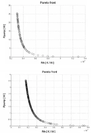
The multi-objective optimization problem was solved using Matlab’s optimization toolbox, along with the parameters and constraints shown in Table 3. The Pareto front of non-inferior solutions for the two heat sink configurations is illustrated in Fig. 6. The vast majority of optimal solutions for the FWμ heat sink (Fig. 6a) is shifted towards channels with small hydraulic diameter and thin walls resulting in a configuration with low thermal resistance and high pressure drop.
A similar pattern, regarding the channel width, is also followed by the optimal solutions of the VWμ heat sink. As depicted in Fig. 6b, the utilization of
microchannels only in the last part of the heat sink reduces the pressure drop and furthermore, it does not deteriorate the total thermal performance of the heat sink, due to the considerably increased microchannel aspect ratio (AR=20) in the part of the heat sink where the cooling fluid has attained a high temperature. Such a high aspect ratio can be possibly fabricated by mechanical machining provided that the fin thickness has a sufficiently high value. It has also been reported in [28] that a microchannel aspect ratio of twenty can be attained using the Deep Reactive-Ion Etching (DRIE) technique.
6. 3-D Flow and Heat Transfer Model
In the second stage of this work, the optimal geometrical parameters of the FWμ heat sink were used for a three dimensional numerical investigation. The numerical model was constructed under the assumptions of steady state, incompressible, single phase and laminar flow. The latter assumption is reasonable considering that for the selected volumetric flow rate and geometrical parameters, the Reynolds number doesn’t exceed the value of 320. Based on these assumptions, the governing equations of flow and energy become:
(continuity)
V 0(momentum) V
V p
V g
(fluid temperature) V
cpT
kfT
(18)
(solid temperature)
ksTs
0to both the large number and small scale of the microchannels. By taking advantage of the existing symmetry instead, the computational domain is reduced to half of the microchannel width and half of the fin thickness [10,29], as depicted in Fig. 7, whereas the top lid thickness is not included in the domain. A symmetry boundary condition is imposed on both the outer vertical planes of the domain. At the inlet, a uniform velocity profile u=ui is imposed, whereas an average static pressure of zero is set at the outlet. A no-slip boundary condition is imposed along the internal channel surfaces. All the outer surfaces, apart from the bottom side where a uniform heat flux is applied, are treated as adiabatic in the solution of the energy equation. Continuity of both temperature and heat flux is specified at the solid-fluid interface. The solid material is aluminum with thermal conductivity ks=237 W/mKand the cooling fluid is water with inlet temperature Ti=298 K and constant thermo-physical properties at a reference temperature of 300K (ks/kf =409). The governing equations along with the boundary conditions were solved using the commercial finite volume solver ANSYS CFX (v.13).
6.3 Numerical solution
None of the solutions that constitute the Pareto front is inferior to the others from the thermal and hydrodynamic performance point of view. Therefore, the final design point was chosen by considering additional aspects that concern the entire CPVT system, such as the total efficiency and the total cost of manufacturing. A FWμ heat sink with a channel width Wch = 314 μm and a fin thickness of Ww = 169 μm was finally chosen as these geometric parameters apart from being a solution of the Pareto front, also correspond to a design of very low parasitic (pumping) power and easier to fabricate in comparison to the other optimal solutions due to its higher fin thickness. The substrate thickness ts was chosen equal to 1.5mm. The total volumetric flow rate branches into the 124 parallel channels of the heat sink and the Reynolds number that characterizes the flow inside each microchannel was 245 (inlet velocity of 0.409m/s). The computational domain was truncated to a total length of L=0.09m, approximately ten times the thermal entry length defined as:
h th
th Z RePrD
z (19)
where Zth 0.011 for a rectangular channel with AR=6 [19]. This simplification is valid since the pressure distribution and both the bulk fluid and bottom wall
temperature distribution in the fully-developed region are linear along the flow
direction [17,21]. Furthermore, the coordinates were properly non-dimensionalized, in order to facilitate the illustration of the numerical results.
The entire computational domain consisting of the fluid and solid part was meshed using hexahedral elements. Numerical tests were conducted using meshes of
increased density in order to verify the grid independency of the results. An increase on the total cell number, from 0.6106 to 1.2106, caused a discrepancy of 1.5% between the values of the maximum fully-developed axial velocity. Upon further refinement to a grid of 1.8106 cells the maximum axial velocity value changed only
The temperature contours on two cross-flow planes near the inlet and the outlet of the microchannel (Fig. 8a) illustrate that the channel bottom wall reaches its
maximum temperature at the outlet, as expected. Furthermore, temperature contours on the channel longitudinal symmetry plane (Fig. 8b) demonstrate a pure forced convection pattern as temperature stratification is clearly absent, although the buoyancy source term was included in the momentum equation for completeness purposes. The relative effect of natural convection in proportion to forced convection
can be quantified using the Archimedes number 2
Re Gr
Ar . The microchannel
hydraulic diameter associated with the optimal FW configuration is calculated equal to 5.3810-4 m, while the circumferentially averaged heat flux is 3.35103 W/m2. Based on these values and taking in mind that Re=245, the mean Archimedes number value is calculated as Ar=2.410-5, meaning that the buoyancy force magnitude is negligible in comparison to inertial forces.
The channel bottom wall mean, circumferentially-averaged and the mean fluid temperature variation along the flow direction, as derived from the 3-D model illustrated in Fig. 9, exhibit clearly a linear trend in the fully-developed region and indicate that the thermal entry length is very short.
Thus, it is justifiable to obtain any further downstream results by simply extrapolating the numerical values up to a length of 0.5 m (exit). The numerical values of the thermal resistance and the pressure drop were compared against the theoretically predicted ones by the 1-D analysis and the results are presented in Table 4. A very good agreement has been clearly accomplished as the discrepancy in the values for the thermal resistance is 2.22% and for the pressure drop 3.79%
respectively.
As the local heat flux and temperature distributions are available form the
numerical simulation, the local convective heat transfer coefficient can be determined at any position of interest using the relation:
z T z T z q z h m w (20)
where Tm(z) is the fluid bulk-mean temperature defined as:
cs , ch A cs , ch cs , ch mm u x,yT x,y dA
A u
T 1 (21)
Fig. 10a shows the variation of the local heat transfer coefficient as a function of the
non-dimensional axial distance Z* at different X* positions on the microchannel bottom wall. It is evident that heat transfer is particularly enhanced in the channel entrance region, while it exhibits a rapid decaying trend as the flow tends to become thermally fully developed. On the other hand, it can also be noted that heat transfer is significantly reduced as the channel side wall is approached. The circumferentially averaged local Nusselt number distribution along the flow direction is plotted in Fig. 10b. The values depicted derive from the well known relation:
f h ave ave k D z h zwhere the average peripheral heat transfer coefficient have(Z) can be found using Eq. (20),after the substitution of the respective heat flux and wall temperature averaged values
P ave qdl P zq 1 (23)
P w ave
,
w T dl
P z
T 1 (24)
where P is the channel perimeter. It can be concluded, that the flow inside the microchannels lies almost entirely in the fully-developed region as the fully- developed Nusselt number value is already attained approximately 3.0 cm
downstream of the inlet. Additionally, the numerically derived fully-developed value agrees well with the analytically predicted one given in [17]. The development of the vertical temperature profiles along the channel streamwise direction can be observed
in Fig. 10c,with a clearly discernible linear part at the bottom, corresponding to the
solid substrate. The temperature profile in the fluid part clearly exhibits the thermal boundary layer growth near the bottom surface, where primarily the heat transfer takes place, while the increase in the fluid temperature in the vicinity of the top wall is due to the higher lateral heat flux in this region, combined with the reduced mass flux (reduced axial flow velocities) in the boundary layer of the upper wall of the
microchannel. Figs. 11a-b depict the velocity profile development along the flow direction on the horizontal plane (XZ) at the microchannel mid-height and on the vertical (YZ) symmetry plane of the microchannel. Yet again, it is evident that the corresponding fully-developed profile for the fluid velocity is rapidly obtained. It can be seen from Fig. 11b that the flow does not exhibit a parabolic but rather a
characteristic flat velocity profile in the y direction, which is in agreement with the theoretical profile [17]. The velocity obtains instead the parabolic profile typical of fully-developed flow in the horizontal (XZ) plane of the microchannel (Fig. 11a).
7. Conclusions
In the present study, a multi-objective methodology was applied in order to optimize the geometrical parameters of two different microchannel heat sink configurations suitable for a linear CPVT system. Thermal resistance and cooling fluid pressure drop were the objective functions used for the optimization procedure. In order to save computational time, one-dimensional models and analytical
correlations were utilized to predict the overall performance of both configurations. The Pareto fronts associated with the optimization problem were obtained through the use of a genetic algorithm. At a second stage, the flow and conjugate heat transfer inside the optimized FWμ heat sink were further investigated using a
three-dimensional numerical model.
microchannels significantly improves the hydrodynamic performance of the heat sink as well.
Through the numerical results, it was demonstrated that heat transfer is
significantly enhanced in the channel entrance region, as the Nusselt number obtains high values in that region, while it exhibits a decaying trend to a constant value as the flow tends to become fully developed. Both the thermal and the hydrodynamic entry length are very small thus allowing the assumption of fully-developed flow and thermal conditions to be made. The flow exhibits the typical parabolic fully- developed velocity profile in the microchannel horizontal plane, while, on the contrary, a characteristic flat profile is obtained in the vertical plane. Furthermore, it was established that, in the fully-developed region, the temperature rises in a linear fashion along the flow direction in both the fluid and the solid region of the heat sink, with the bottom wall, thus, reaching its maximum temperature exactly at the channel outlet.
Finally, it can be deduced that the 1-D analysis can fairly accurately represent the flow and conjugate heat transfer inside a microchannel, as it agrees well to the 3-D numerical results and to previously published experimental data, being therefore suitable for optimization procedure purposes.
References
[1] W. Qu, I. Mudawar, Experimental and numerical study of pressure drop and heat transfer in a single-phase micro-channel heat sink. International Journal of Heat and Mass Transfer 45 (2002), pp. 2549–2565.
[2] D.B. Tuckerman, R.F.W. Pease, High-performance heat sinking for VLSI. IEEE Electron Device Letters 2 (1981), pp. 126–129.
[3] T. M. Harms, M. J. Kazmierczak, F. M. Gerner, Developing convective heat transfer in deep rectangular microchannels. International Journal of Heat and Fluid Flow 20 (1999), pp. 149-157.
[4] W. Qu, I. Mudawar, Analysis of three-dimensional heat transfer in micro-channel heat sinks. International Journal of Heat and Mass Transfer 45 (2002), pp. 3973– 3985.
[5] B. Agostini, M. Fabbri, J.E. Park, L. Wosjtan, J.R. Thome, B. Michel, State of the art of high heat flux cooling technologies. Heat Transfer Engineering 28 (2007), pp. 258-281.
[6] S.G. Kandlikar, A.V. Bapat, Evaluation of jet impingement, spray and microchannel chip cooling options for high heat flux removal. Heat Transfer Engineering 28 (2007), pp. 911-923.
[7] N. Goldberg, Narrow channel forced air heat sink. IEEE Transactions on Components Hybrids and Manufacturing Technology CHMT-7 (1984), pp. 154-159.
pp. 313-321.
[9] S. Lee, W. Qu, Thermal design methodology for low flow rate single phase and two-phase micro channel heat sinks. IEEE Transactions on Components and Packaging Technologies 30 (2007), pp. 830-841.
[10] D. Liu, S.V. Garimella, Analysis and optimization of the thermal performance of microchannel heat sinks. International Journal of Numerical Methods for Heat and Fluid Flow 15 (2005), pp. 7-26.
[11] N. Mueller, L.G. Frechette, Optimization and design guidelines for high flux micro-channel heat sinks for liquid and gaseous single-phase flow. Thermomechanical Phenomena in Electronic Systems-Proceedings of the Intersociety Conference 2002, pp. 449-456.
[12] D. Copiello, G. Fabbri, Multi-objective optimization of the heat transfer from longitudinal wavy fins. International Journal of Heat and Mass Transfer 52 (2009), pp. 1167-1176.
[13] A. Husain, K.Y. Kim, Enhanced multi-objective optimization of a microchannel heat sink through evolutionary algorithm coupled with multiple surrogate models. Applied Thermal Engineering 30 (2010), pp. 1683-1691.
[14] S. Ndao, Y. Peles, M.K. Jensen, Multi-objective thermal design optimization and comparative analysis of electronics cooling technologies. International Journal of Heat and Mass Transfer 52 (2009), pp. 4317-4326.
[15] W. Escher, B. Michel, D. Poulikakos, A novel, high performance, ultra thin heat sink for electronics, International Journal of Heat and Fluid Flow 31 (2010), pp. 586-598.
[16] A. Kraus, A. Bar-Cohen, Thermal Analysis and Control of Electronic Equipment, McGraw-Hill, New York, 1983.
[17] R.K. Shah, A.L. London, Laminar Flow Forced Convection in Ducts: a Source Book for Compact Heat Exchanger, Academic press, New York, 1978.
[18] R.D. Blevins, Applied Fluid Dynamics Handbook, Van Nostrand Reinhold Company, New York, 1984.
[19] R.K. Shah, M.S. Bhatti, in: S. Kakac, R.K Shah, W. Aung (Eds.), Handbook of Single Phase Convective Heat Transfer, Wiley & sons, New York, 1987 (Chapter 3).
[20] R.K. Shah, A correlation for laminar hydrodynamic entry length solutions for circular and noncircular ducts. Journal of Fluids Engineering 100 (1978), pp. 177-179.
[22] J. Barrau, D. Chemisana, J. Rosell, L. Tadrist, M. Ibañez, An experimental study of a new hybrid jet impingement/micro-channel cooling scheme. Applied Thermal Engineering 30 (2010), pp. 2058-2066.
[23] Y. Jaluria, Simulation-based optimization of thermal systems. Applied Thermal Engineering 29 (2009), pp. 1346–1355.
[24] K. Deb, Multi-Objective Optimization using Evolutionary Algorithms, Wiley, London, 2001.
[25] K. Deb, A fast and elitist multiobjective genetic algorithm: NSGA-II, IEEE Transactions on Evolutionary Computation 6 (2002), pp. 182-197.
[26] The Mathworks Inc., Genetic Algorithm and Direct Search Toolbox for use with MATLAB, User’s Guide, Version 1, 2004.
[27] R. Hilbert, G. Janiga, R. Baron, D. Thévenin, Multi-objective shape optimization of a heat exchanger using parallel genetic algorithms. International Journal of Heat and Mass Transfer 49 (2006), pp. 2567-2577.
[28] A. Husain, K.Y. Kim, Shape optimization of channel heat sink for micro-electronic cooling, IEEE Transactions on Components and Packaging Technologies, 31 (2008), pp. 322-330.
Figure captions
Fig. 1 Schematic of the CPVT system.
Fig. 2 FWμ heat sink: (a) Layout and (b) equivalent total thermal resistance network.
Fig. 3 VWμ heat sink: (a) Layout and (b) equivalent convective thermal resistance
network.
Fig. 4 Response values (a) for the thermal resistance and (b) for the pressure drop of
the FWμ heat sink.
Fig. 5 Response values (a) for the thermal resistance and (b) for the pressure drop of
the VWμ heat sink.
Fig. 6 Pareto front of non dominated solutions (a) for the FWμ heat sink and (b) for
the VWμ heat sink.
Fig. 7 Computational domain for the 3-D model.
Fig. 8 Temperature contours on planes, (a) transversal and (b) parallel to the flow
direction.
Fig. 9 Mean temperature distributions in the fluid and the solid region.
Fig. 10 (a) Local heat transfer coefficient distribution, (b) circumferentially averaged
local Nusselt number distribution, (c) development of the vertical temperature profile at the channel vertical symmetry plane.
Fig. 11 Velocity profile development: (a) Horizontal velocity profiles at the channel
Table captions
Table 1 Validation of the analytical model.
Table 2 Design constraints and coefficients of the surrogate functions.
Table 3 Parameters of the genetic algorithm.
Tables
Table 1
Validation of the analytical model.
Rth (K/W) Δp (Pa)
Wch (μm) Ww (μm) Hch (μm) q’’ (W/cm2) Vtot(mL/s) Experimental 1-D model Experimental 1-D model
Table 2
Design constraints and coefficients of the surrogate functions.
FWμ VWμ
Constraints
tot
V =30.0 mL/s Vtot=30.0 mL/s
Hch=6Wch Hch=2Wch,init
2 2
1 w
i , ch i , ch
W W
W
Ww=0.2Wch,init
Surrogates coefficients
p00 0.008018 p30 -1.66E+05 r0 0.1711 p10 2.033 p21 -2.28E+06 r1 0.008 p01 0.7274 p12 5.79E+06 c1 4.0010-9
p20 1567 p03 -3.84E+06 c2 -2.9822 p11 -3758 b1 1.47E-10
p02 2819 b2 -3.484
Table 3
Parameters of the genetic algorithm.
Population of individuals 200
Generations 500
Crossover probability 0.8
Migration probability 0.2
Constraints FWμ 110-4x
1510-4 & 110-4x2510-4 VWμ 110-3x
Table 4
Comparison of the numerical values to the analytical ones.
Rth (K/W) Δp (Pa)
Wch (μm) Ww (μm) Hch (μm) q’’ (W/cm2) Vtot (mL/s) Numerical 1-D model Numerical 1-D model