City, University of London Institutional Repository
Citation
: Nikolić, B., Khan, S.H. & Gabdullin, N. (2016). Development of non-conventional
instrument transformers (NCIT) using smart materials. Journal of Physics: Conference Series, 772(1), 012065.. doi: 10.1088/1742-6596/772/1/012065This is the accepted version of the paper.
This version of the publication may differ from the final published
version.
Permanent repository link:
http://openaccess.city.ac.uk/16377/Link to published version
: http://dx.doi.org/10.1088/1742-6596/772/1/012065
Copyright and reuse:
City Research Online aims to make research
outputs of City, University of London available to a wider audience.
Copyright and Moral Rights remain with the author(s) and/or copyright
holders. URLs from City Research Online may be freely distributed and
linked to.
City Research Online: http://openaccess.city.ac.uk/ [email protected]
Development of non-conventional instrument transformers
(NCIT) using smart materials
Bojan Nikolić, Sanowar Khan and Nikita Gabdullin
City University London, Northampton Square, London EC1V 0HB United Kingdom
E-mail: [email protected]
Abstract. In this paper is presented a novel approach for current measurement using smart materials, magnetic shape memory (MSM) alloys. Their shape change can be controlled by the application of magnetic field or mechanical stress. This gives the possibility to measure currents by correlating the magnetic field produced by the current, shape change in an MSM-based sensor and the voltage output of a Linear Variable Differential Transducer (LVDT) actuated by this shape change. In the first part of the paper is presented a review of existing current measurement sensors by comparing their properties and highlighting their advantages and disadvantages.
1. Introduction
Under the term conventional instrument transformers is usually considered measurement of current and voltage using transformers with an iron core. Their design has reached its optimum and has not changed significantly over the last few decades. With the development of electronics and application
of electronic circuits in all spheres of today’s life, one of their main disadvantages came to the fore - incompatibility with modern measurement equipment.
This is one of the main reasons why the so-called non-conventional instrument transformers (NCIT) have gained considerable attention in recent years. NCITs are usually transformers without ferromagnetic core or those, which, instead of the standard iron core use other materials that have a better response to rapidly changing signals. As a part of measurement systems, different electrical circuits are used with NCITs. Moreover, they are often integrated in the NCIT. This design flexibility provides full compatibility with modern digital measuring devices and opens up possibilities for many applications.
Today, there are many different devices and principles for current measurement. The existence of a significant number of papers dealing with this subject shows popularity and importance of this topic, but also shows that there still exist many unsolved problems and many challenges that need to be overcome. Some of the proposed measurement principles have already found industrial application, while others are still explored for such applications.
This paper presents a review of existing principles for sensors for current measurement and proposes a novel approach using magnetic shape memory (MSM) smart alloys, which change shape when subjected to magnetic fields.
IMEKO2016 TC1-TC7-TC13 IOP Publishing
2. Sensors for current measurement
2.1. Rogowski coils
One of the most popular sensors for current measurement is Rogowski coil. These coils do not have any ferromagnetic core, which allows measurement of current over a wide range. Using the same Rogowski coil, it is possible to measure currents larger than 1 MA and as small as few mA [1]. Furthermore, current measurement over this wide range is linear since there is no core that can get saturated.
Their measurement principle is based on “sensing” the magnetic field produced by current,
meaning that they cannot be used for measurement of DC currents. The measurement frequency range is approximately 0.1 Hz-1 GHz [1], so they can be successfully used for the measurement of AC currents as well as transients.
Rogowski coils are small, compact, lightweight and their power consumption is very low, which makes current measurements in high-voltage circuits easy and safe owing to the absence of any electrical connections with the measured circuit. There are also the so-called flexible designs of Rogowski coils which allow measurements without interrupting the current circuit. Rogowski sensors cause no disturbances to the measurement system since they draw no power from the main circuit and the inductance added into the circuit due to the presence of the coil is only a few pH [1].
Moreover, these coils require almost no maintenance, except for periodical examination for physical damage if the coils are exposed to some harsh environment. They can be calibrated at any convenient current level and later used for any current level, including very large currents. They cause no damage by large overload.
Furthermore, considering that the same device can be used for current measurement, control and protection and that it has low price, it is more than clear why Rogowski coils found wide applications in industry. However, there are several drawbacks which points to other instruments for current measurement.
One of their main disadvantages is sensitivity to surrounding electromagnetic fields, meaning that some kind of shielding is needed. Their output is very small which necessitates proper grounding and
shielding. The voltage on the coil’s output is in order of µV for primary currents bellow 100A.
However, at same time, such low sensitivity can actually be their advantage in some applications. Measurement errors are typically in the range 5-20% of rated current [2], but there are some solutions which increased their accuracy [3] where the error is in the range of 0.5-5%. This problem is partly solved by the design of printed circuit board Rogowski coils, which have better accuracy (0.2-0.5%) and higher immunity to external fields compared to classical Rogowski coils, but at same time their output voltage is lower [4].
Another drawback of Rogowski-coil based current measurement is the need for an integrator for vast majority of measurements. In addition to the fact that the integrator affects the accuracy and stability of Rogowski sensor, the measurements conducted usually require that sampling, A/D conversions and data transmissions are done at measurement locations, which can be impractical in some situations. This also means that if all these electrical components are placed at a high voltage site, a separate power supply is needed.
2.2. Optical current sensors
Optical current sensors usually use one of the two principles for measurement of current: change of fibre-grating wavelength or the Faraday’s effect. There are two main types of fibre gratings: short -period gratings or fibre Bragg gratings (FBG) and long--period gratings (LPG). It should be noted at
the outset that current sensors based on Faraday’s effect (effect of plane rotation of polarised light when it travels through a magnetic field) have too low sensitivity for practical applications, are extremely difficult to implement in an accurate and stable way and may be only affordable for high voltage lines [5], [6]; this means more attention will be paid to sensors based on the first of the above optical principles.
IMEKO2016 TC1-TC7-TC13 IOP Publishing Journal of Physics: Conference Series772(2016) 012065 doi:10.1088/1742-6596/772/1/012065
One of the main advantages of optical sensors is the fact that there is an optical signal at their output which makes them very convenient for use in modern systems where a lot of fibre optics is used. Unlike Rogowski sensors optical sensors are not sensitive to surrounding electromagnetic fields and they are smaller and more compatible to the requirements of modern smart grids. Their nonconductive nature makes them electrically passive which, along with their chemical inertness make them an excellent choice for measurement in corrosive and explosive environments. Generally, optical
sensors don’t saturate and have linear outputs comparable to Rogowski sensors.
Optical sensors are lightweight which helps to produce portable equipment, but also a collector, which contains all accompanying electrical components and, hence does not need to be placed near the measurement location when fibre optics is used. This is very useful for current measurement in the presence of high voltages. This is not only because it is easier to place equipment and manipulate later with it, but also because sensor electronics at the ground level is separated from sensing fibre optic at high voltage. They can be easily used for remote operations and inspections over long distances. Even though it is possible to add to the list of very positive features of optical sensors features as large bandwidth and possibility to achieve highly accurate current measurements, there are also several drawbacks of this technology. They are very sensitive to vibrations, temperature and other environmental effects making outdoor installation complex. The temperature sensitivity of FBG is typically around 6 pm/˚C and for LPG can be as high as 3.4 nm/˚C [7]. Their output data are more unstable than those of the Rogowski coils [2].
The time delay of fibre optic current sensor’s output signal is generally around 100µs [8], while
some magneto-optical sensors (sensors which use the Faraday’s effect) with GHz response have been
produced [9]. One of the main disadvantages of current measurement using FBG or LPG is often very complex demodulation system needed for the wavelength shift measurement. High production costs due to high demand for materials and complex production process make it difficult for them to achieve mass production.
2.3. Magnetic sensors
Magnetic sensors attracted a lot of attention in recent years. This primarily attributable to the fact that these sensors are seen to be better in a good number of theoretical papers dealing with these materials and proposing different operating principles. The proposed measurement systems using magnetic sensors usually involve some other transducers and other technologies (very often optical fibre grating), what makes these systems very complex and susceptible to errors. So far many such magnetic sensors have been proposed. Among them are magnetoresistive sensors, which work on the principle that magnetic field affects the resistance of the sensor. This could be based on anisotropic magnetoresistance (AMR), giant magnetoresistance (GMR), magnetic tunnel junction (MTJ) and giant magnetoimpedance (GMI) sensors. Sensors which use magnetic force produced by measured current have been also proposed, as well as sensors made of magnetostrictive materials. Of particular interests are magnetostrictive materials, which belong to the group of giant magnetostrictive materials (GMM). All magnetic sensors are generally very small and light which makes them interesting for many applications.
Magnetoresistive magnetometers can be energised by applying a constant current and the output voltage is proportional to the strength of magnetic field. They are especially attractive for low cost applications. Magnetoresistive sensors are generally energy efficient devices (for example, AMR
sensors’ power consumption is less than 1W) [5]. They can sense very low magnetic fields (for AMR
sensors this can be as low as 0.1nT) as well as a quite strong fields (GMR sensors can be used in fields as large as 0.1T) [9].
Increased interest in magnetostrictive sensor technology results from improvements in the performance of magnetostrictive materials and led to an increased use of these sensors for a wide range of applications.
Despite what has been said earlier, these magnetic sensors have several serious drawbacks that prevent their even wider application. They tend to be highly nonlinear and suffer from hysteresis
which usually requires some compensation methods to be used to linearise the sensor. Besides, they are also sensitive to temperature changes and, often to vibrations. For example, magnetostrictive
materials have a temperature dependence in the order of 5ppm/˚C [6].
Magnetostriction is a unipolar phenomenon which means that a positive strain is produced for opposite directions of the magnetic field. Furthermore, relatively large magnetic field is needed to make use of the magnetostrictive property. Also since magnetostrictive sensors do not transduce current directly into an electrical form, at least one more step is needed for current measurement. For magnetoresitive materials the change of resistance caused by an external magnetic field is very small. For example, for permalloy, which is the most common used material for AMR sensors, this is less than 4% [9].
The impedance of GMI sensors depends strongly on both the magnetic field strength and its frequency. To benefit from the GMI effect, high frequency current of the order of GHz is needed which limits their application as sensors [9].
2.4. Hall effect sensors
Another very popular method of measuring current is by the use of Hall effect sensors. These sensors have easier fabrication process and lower cost compared to Rogowski coils and optical sensors. They can measure currents over a relatively wide frequency range (from DC-1MHz [9]) provided that the current values are between 10mA and 35kA [10]. They are usually very small and linear (linearity errors less than 1% over significant operating range) [11] and have modest power consumption between 0.1-0.2W [9]. It is possible to install them without interrupting current circuit.
In general, Hall effect sensors are sensitive to temperature, stress and ageing. Consequently these sensors have non-negligible offset and sensitivity drifts. Without calibration, the typical temperature
drift is 500ppm/˚C and ageing drift of up to 2% [12]. They are also affected by external magnetic
fields and can be very sensitive to the relative positioning of the current-carrying conductor and the sensor. Hall effect sensors are usually made of semiconductor materials which are highly piezoresistive.
3. Novel sensing principle based on ‘smart alloys’
Magnetic shape memory (MSM) alloys are relatively new “smart” materials which change their shape when subjected to external magnetic fields. The Ni-Mn-Ga alloys are the most studied MSM alloys which have been shown to have enormous potential to be used in actuators and sensors. MSM alloys have a remarkable magnetic field induced (MFI) strain, maximum theoretical value of which varies,
depending on material’s microstructure from 6% for the most studied five-layered modulated (10M) to 12% for non-modulated (NM) [13], [14]. These are more than one order of magnitude higher than maximum strains produced by conventional magnetostrictive and piezoelectric materials reaching strains of well-known thermal shape memory alloys. However, MSM alloys respond to magnetic field excitation significantly faster and are predicted to have very long fatigue life if certain operational conditions are met. As it is obvious from their reversible properties MSM alloys can be used both as position and stress sensors [15].
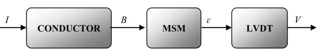
The basic principle of a novel current sensor based on MSM alloys, proposed in this paper relies upon the proportionality of the strain produced by an MSM element which is subjected to a magnetic field produced by the current whose magnitude is being measured. This is shown schematically in figure 1 in which the output voltage, V generated by the LVDT is proportional to the strain, ε
produced by the MSM element. This MSM strain is in turn proportional to the magnetic field B which is ultimately proportional to the current in the conductor, I (measurand).
IMEKO2016 TC1-TC7-TC13 IOP Publishing Journal of Physics: Conference Series772(2016) 012065 doi:10.1088/1742-6596/772/1/012065
Figure 1. Schematic showing the proposed current-measurement system based on magnetic shape memory (MSM) alloys.
The sensor system consists of an MSM element and a suitably coupled LVDT. The magnetic field
(B) produced by a current (I) in the conductor is converted into displacement of the MSM element (ɛ)
which changes the output voltage (V) of the LDVT. This approach allows sensing of very high currents remotely essentially by sensing the magnetic field produced by these currents.
The main disadvantages of the proposed MSM-based current sensors are attributable to temperature sensitivity and magneto-mechanical hysteresis of currently available MSM alloys. The former is associated with the upper temperature limit determined by the austenite-martensite transformation temperature of 60-80˚C [16] for conventional alloys and by the temperature-dependent twinning stress. The hysteresis is also associated with this twinning stress. The twinning stress can be seen as an energy barrier to be overcome for propagating twin boundaries in the MSM material and hence, changing the shape of the MSM element. Consequently the sensitivity of the proposed sensor is inversely proportional to the magnitude of the twinning stress. Twinning stress is still considerably high for conventional type I twin MSM elements. However, less studied type II twin crystals can be very promising for sensor applications due to low twinning stress which does not depend on temperature [17]. This results in very low hysteresis together with good temperature stability.
Due to larger strain range MSM alloys can be used in applications where GMM materials are not adequate. For instance, a typical 20mm MSM element with 5M microstructure elongates by up to 1.2mm under no larger than 0.6T magnetic field if the mechanical load is small [18]. Furthermore,
relatively high magnetic field is needed to “activate” an MSM element which essentially suggests their possible application for measuring only large currents.
4. Conclusions
It seems the incompatibility of conventional measurement transformers with modern equipment is one of the main reasons for searching novel current-sensing and measurement solutions based on different alternative principles. The first part of this paper gives a brief overview of already existing sensing principles of current NCITs by comparing their properties and focusing on their advantages and disadvantages.
Although Rogowski coils, Hall sensors, conventional optical sensors as well as measurement principles based on FBG are dominant at the moment, there are still many unsolved problems.
In this paper, though at an early stage we have proposed the concept of a novel alternative approach for current measurement using magnetic shape memory (MSM) smart materials. The main idea behind this approach is to correlate the magnetic field produced by the current to be measured with the output voltage of an LVDT actuated by the shape change of an MSM element under the magnetic field. There are, however many challenges to be overcome before a viable prototype can be designed, built
and tested under laboratory and ‘field’ conditions. These include magneto-mechanical and thermo-mechanical stability of MSM material under variable ambient conditions, achievement of high degree of linearity at every stages of transition between the physical sub-systems shown in figure 1. This essentially means ensuring linearity of interdependent variables I, B, ɛ and V. This work is being undertaken at present by numerical finite element modelling and design.
CONDUCTOR MSM LVDT
I B ɛ V
[image:6.595.143.459.123.173.2]References
[1] Metwally I A 2010 Self-integrating Rogowski coil for high-impulse current measurement
IEEETrans. on Instrumentation and Measurement59 No. 2 353-360
[2] Cao L 2010 Application Comparison of Rogowski-type and Optical-type Electronic Current Transformer CICED Int. Conf. (Nanjing) pp. 1-5
[3] Frolov G, Grudin O and Warland T 2008 Compensating Rogowski coils for current measurement Electronic Engineering Times pp. 31-32
[4] Kojovic Lj A et al. 2010 Practical Aspects of Rogowski Coil Applications to Relaying IEEE PSRC Special Report
[5] Kirkham H 2009 Current Measurement Methods for the Smart Grid IEEE PES General Meeting
pp. 1-7
[6] Mora J, Díez A, Cruz J L and Andrés M V 2000 A magnetostrictive sensor interrogated by fiber gratings for DC-current and temperature discrimination IEEE Photonics Technology
Letters12, No. 12 1680-82
[7] Thyagarajan K and Ghatak A 2007 Fiber Optic Essentials (John Wiley & Sons Inc.).
[8] Viawan F A, Wang J, Wang Z and Ying Yang W 2009 Effect of Current Sensor Technology on Distance Protection IEEE/PESPower Systems Conf. and Exposition pp 1-7
[9] Lenz J and Edelstein A S 2006 Magnetic sensors and their applications IEEE Sensors J6 No. 3 631-649
[10] Tsai Y P, Chen K L, Chen Y R and Chen N 2014 Multifunctional coreless Hall-effect current transformer for the protection and measurement of power systems IEEE Trans. on
Instrumentation and Measurement63 No. 3 557-565.
[11] Ramsden E 2006 Hall-Effect Sensors: Theory and Application (Elsevier Inc.)
[12] Pastre M and Kayal M 2005 A Hall Sensor-Based Current Measurement Microsystem With Continuous Gain Calibration IEEE PhD Research in Microelectronics and Electronics2 95-98
[13] Murray S J, Marioni M, Allen S M, O’Handley R C and Lograsso T A 2000 6% magnetic-field- induced strain by twin-boundary motion in ferromagnetic Ni–Mn–Ga Appl. Phys. Lett. 77 No. 6 886
[14] Sozinov A, Lanska N, Soroka A and Zou W 2013 12% magnetic field-induced strain in Ni-Mn- Ga-based non-modulated martensite Appl. Phys. Lett. 102 No. 2 021902
[15] Stephan J M, Pagounis E, Laufenberg M, Paul O, Ruther P and Reorientation A M 2011 A novel concept for strain sensing based on the ferromagnetic shape memory alloy NiMnGa
IEEE Sens J 11 No. 11 2683–89
[16] Pagounis E, Chulist R, Szczerba M J and Laufenberg M 2014 High-temperature magnetic shape memory actuation in a Ni–Mn–Ga single crystal Scr. Mater.83 29–32
[17] Straka L, Soroka A, Seiner H, Hanninen H and Sozinov A 2012 Temperature dependence of twinning stress of Type I and Type II twins in 10M modulated Ni-Mn-Ga martensite Scr.
Mater.67 No. 1 25–28
[18] Pagounis E and Müllner P 2014 Recent Developments in Magnetic Shape Memory Actuation
Proc. Actuator 86–91
IMEKO2016 TC1-TC7-TC13 IOP Publishing Journal of Physics: Conference Series772(2016) 012065 doi:10.1088/1742-6596/772/1/012065