City, University of London Institutional Repository
Citation
:
Karcanias, N., Leventides, J. & Livada, M. (2014). Multi-parameter structural
transformations of passive electrical networks and natural frequency assignment. In: 22nd
Mediterranean Conference of Control and Automation (MED). (pp. 984-989). IEEE. ISBN
9781479959006
This is the accepted version of the paper.
This version of the publication may differ from the final published
version.
Permanent repository link: http://openaccess.city.ac.uk/7278/
Link to published version
:
http://dx.doi.org/10.1109/MED.2014.6961502
Copyright and reuse:
City Research Online aims to make research
outputs of City, University of London available to a wider audience.
Copyright and Moral Rights remain with the author(s) and/or copyright
holders. URLs from City Research Online may be freely distributed and
linked to.
City Research Online:
http://openaccess.city.ac.uk/
[email protected]
Multi-Parameter Structural Transformations of Passive Electrical
Networks and Natural Frequency Assignment
Nicos Karcanias
1, John Leventides
1, and Maria Livada
1Abstract— The paper examines the problem of systems re-design within the context of passive electrical networks by considering the problem of multi-parameter changes, their representation and impact on properties such as characteristic frequencies. The general problem area is the modelling of systems, whose structure is not fixed but evolves during the system lifecycle. The specific problem we are addressing is the study of effect of changing the topology of an electrical network that is changing individual elements of the network into elements of different type and value, augmenting / or eliminating parts of the network and developing a framework that allows the study of the effect of such transformations on the natural frequencies. This problem is a special case of the more general network redesign problem. We use the Impedance-Admittance models and we establish a representation of the different types of transformations on such models. For the case of network cardinality preserving transformations, we formulate the natural frequencies assignment problem as a problem of zero assignment of matrix pencils by additive struc-tured transformations and this allows the deployment of the Determinantal Assignment Problem framework for the study of assignment and determination of fixed natural frequencies.
I. INTRODUCTION
The problem of redesigning autonomous (no inputs or outputs) passive electric networks [1], [2] aims to change the network (natural frequencies) by modification of the types of elements, possibly their values, interconnection topology and possibly addition, or elimination of parts of the network. As such, this is a problem that differs considerably from a standard control problem, since it involves changing the sys-tem itself without control and aims to achieve the desirable system properties, as these may be expressed by the natural frequencies by system re-engineering. In fact, this problem involves the selection of alternative values for dynamic ele-ments (inductances, capacitances) and non-dynamic eleele-ments (resistances) within a fixed interconnection topology and/or alteration of the network interconnection topology and pos-sible evolution of the (increase of elements, branches). The aim of the paper is to define an appropriate representation framework that allows the deployment of control theoretic tools for the re-engineering of properties of a given network when there are multi-parameter variation within a fixed cardinality network topology and introduce an appropriate Determinantal Assignment framework for the study of the effects of such transformations on the natural frequencies of the network. We use impedance and admittance modelling
1Nicos Karcanias, John Leventides and Maria Livada are with Systems
and Control Research Centre, School of Engineering and Mathematical Sciences, City University London, Northampton Square, London EC1V 0HB
[2], [3] for passive electrical networks and consider here sys-tems with no sources (autonomous descriptions), since our current interest is on the shaping of natural frequencies. The emphasis here is on the study of the different representations of the passive network that enable the investigation of the transformations on such models as structural transformations. We identify two natural topologies expressing the structured transformations, which are identified as theimpedance graph
and the admittance graph of the network. The problem considered here is:
• Define the representation of changes of a many dy-namic, or non-dynamic elements with preservation, or alteration of existing topologies without changes in the overall nodal or loop cardinality of the network and define a framework for studying natural frequency assignment.
The overall aim is to explore the structure and representations of the Impedance-Admittance modelW(s)and introduce ap-propriate representation of the above transformations which enable the study of the shaping of natural frequencies. Matrix representations of the above transformations are introduced as additions of structural transformations on theW(s)model. A simplification of W(s) is achieved by restricting the study to the case of RL inductor) or RC (resistor-capacitor) networks where the corresponding impedance or admittance models become matrix pencils. For such cases, it has been shown that the single parameter variation problem (dynamic or non-dynamic) is equivalent to Root Locus problems [4]. The general case of RLC networks is con-sidered and we introduce the notion of companion pencil, sF+G, that has the same non-zero structure with W(s) and preserves the natural topological properties of the network. We establish the representation of cardinality preserving transformations as additive transformations on sF+G [5] and show that natural frequency assignment may be studied within the exterior algebra framework of the Determinantal Assignment Problem [6], [7], [8]. This paper focuses on the formulation of the problem and the presentation of the respective frequency assignment framework.
II. PASSIVE NETWORK MODELS AND TOPOLOGIES
A. Impedance and Admittance Models
In the network loop analysis method, the variables are selected such that the vertex law is automatically satisfied. Here, we consider only planar graphs withb branches andn
of the meshes and we define them as loop variables. The path law is then written for each mesh and substitutions are made for the across variables in terms of the loop variables using the elemental equations. This way the overall system is reduced to a number of meshes, which areq= (b−n+1)[3] and will be referred to asloop cardinalityof the network. The process of working out the equations involves the selection of internal independent loops [3], [9], the definition of loop currents and the transformation of current sources to equivalent voltage sources. If we denote by (f1,f2, ...,fq)
the set of the Laplace transforms of the loop currents and
by (us1, ...,usq) the set of Laplace transforms of equivalent
voltage sources, then the loop or impedance model is defined by [10]:
Z(s)f(s) =us(s) (1)
where Z(s) has elements zii(s) expressing the sum of
impedances in loopiand is the sum of impedances common between loops i and j. This is referred to as the loop or
impedance modeland it is an integral-differential symmetric matrix and Z(s) is referred to as the network impedance matrix.
Alternative modelling is the method using the across variables from each vertex to some reference vertex are chosen as the unknowns in terms of which the final set of equations is formulated and are called node variables. These variables automatically satisfy the path laws. The vertex equation is then written at each node, and the through variables are then expressed directly in terms of the node variables as related by the elemental equations. The process eliminates all variables except the node variables and has a number of equations, which is in general: p= (n−1) and will be referred to asnodal cardinality of the network. The node method is the dual to the loop method and the basic steps involve the selection of internal nodes, definition of the corresponding node voltages and the transformation of the voltage sources to equivalent current sources (Norton’s theorem). If we denote by (u1,u2, ...,un)the Laplace
trans-forms of the reduced node voltages and by (is1, ...,isn) the
set of Laplace transforms of equivalent current sources, then the node or admittance model is defined by [2]:
Y(s)u(s) =is(s) (2)
where:yii(s) is the sum of admittances in nodei ; yi j(s)is
the sum of admittances common between nodesiand j. This is referred to as thenode or admittance model and it is an integral-differential symmetric matrixY(s) is referred to as thenetwork admittance matrix.
B. The Autonomous Natural Impedance-Admittance Model and Topologies
When we consider networks with no inputs (no current, or voltage sources) the resulting admittance, or impedance network models may be described in a unifying way as:
{pB+p−1C+D}x(t) =0 (3) where p, p−1 are respectively the differential, integral operators respectively andx(t)is the vector of nodal voltages,
or loop currents. Such a description may be referred to as the naturalautonomous networkdescription and the operator
W(s) =sB+s−1C+D will be called the natural network
operator. Note that for the case of admittance we have that B is a matrix of A-type elements (i.e. mass, inertance, capacitance),Cis the matrix of T-type elements (i.e. spring, inductance) and D is a matrix of D type elements (i.e. resistance). For the case of impedance the reverse holds true. Hence, B is the matrix of T-type elements, C is the matrix of A-type elements and D is the matrix of D-type elements. The symmetric operatorW(s) is thus a common description of Y(s) and Z(s) matrices. The operator W(s)
describes the dynamics of the network and of special interest are the properties of its zeros.
Network modelling uses the system graph, which is the basic topological structure that generates the system equations. Apart from the system graph we may introduce some additional topologies, which are linked to the specifics of the Node and Loop analysis. The detailed topological structures that emerge depend on the nature of the elements in the network. The ideal lumped elements are classified as energy-storage and dissipation elements. The mass, inertia and capacitance store energy by virtue of their across-variables (velocity, voltage) and they are referred to as A-type energy storage units[2]. Springs and inductances store energy by virtue of their through- variables and are called
T-typeenergy- storage devices. The dampers and resistances dissipate energy and will be called D-typeelements.
The Vertex Topology:Every network may be represented in terms of a set of vertices, or nodes and all branches between two vertices may be represented by an admittance function. Specification of the values of the across variables of the vertices defines the values of all through variables in the network. The nature of the elements in the branches of the natural vertex graph defines an element dependent topology, which is characterized by adjacency type matrices. If we set the external sources to zero, the reduced graph will be referred to as thekernel vertex graph. For a given kernel vertex graph we define A-vertex sub-graph by eliminating from the kernel vertex graph all T- and D-type edges. Similarly, we define the T-vertex sub-graph by eliminating all A- and D-type edges and the D-vertex sub-graph by eliminating all A- and T-type edges. The sub-graph of the natural vertex graph obtained by eliminating all T-, D-, A-type elements represents the location of the through variable sources and will be called the source-vertex sub-graph, or simply S-vertex sub-graph. If we denote by Gv the natural
vertex graph of a network and by Gv,a,Gv,t,Gv,d,Gv,s the
corresponding A-, T-, D-,S- sub-graphs ofGv, then the latter
define a decomposition ofGv, which may be denoted as:
Gv=Gv,a∪G˙ v,t∪G˙ v,d∪G˙ v,s (4)
If Av,a; Av,t; Av,d; Av,s are the adjacency matrices of
the sub-graphs Gv,a,Gv,t,Gv,d,Gv,s then the quadruple
(Av,a; Av,t; Av,d; Av,s) provides a representation of the vertex
The loop topology:The loop topology is a notiondualto that of the vertex topology and it is based on the following principle: Every network ofnvertices andbedges (branches) may be represented by q = (b−n+1) loops leading to independent equations. All branches common between two loops may be represented by an impedance function. Spec-ification of the values of through variables for the loops defines the values of all across variables in the network. In a similar way to the case of nodal analysis, we may define the
loop topology based on the kernel loop graph and its sub-graphs the A-loop sub-graph, the T-loop sub-graph, the D-loop sub-graphand thesource-loop sub-graph[2]. A similar decomposition to that of (4) also holds here.
C. The Linearisation of the Autonomous Natural Impedance-Admittance Model
Starting from the integral-differential model of (6), de-scribed by the operatorW(s)the natural question that arises is how we can transform it to an equivalent first-order, matrix pencil description, which preserves the topology of the network. Starting from the autonomous descriptions (6) we introduce a new set of variables, bx= [x,x]˜t, p−1x=ex
which reduces (3) to a first order description given by equation (5) which has an associated matrix pencil sF+G
defined by (6) and referred to as the network matrix pencil which is defined:
B 0 0 I
px pex
=
−D −C I 0
x e x
(5)
sF+G=
sB+D C −I sI
(6)
Note that the above autonomous differential description pre-serves the topological properties of the network as these are represented by the B, C, D matrices, but its dimensionality is not necessarily minimal (dimensionality of sF+G). The pencil derived is structured, but not symmetric in the general case and it will be referred to as the companion pencil of the network. The zeros ofW(s)define the natural frequencies of the network. Note that:
sB+D C −I sI
=sks B + s−1C+D
or
|sF+G|=sk· |W(s)|,W(s)∈ℜkxk(s) (7)
Remark (1): The non-zero natural frequencies of the
net-work are given by the zeros of the pencilsF+Gand thus this pencil ,may be used for the study of assignment of natural frequencies under different types of transformations. For the special cases where the network is characterized only by A-and D- type elements or T- A-and D- type elements thenW(s)
has the following special forms:
e
W(s) =sB+D,Wb(s) =bsC+D,bs=s
−1 (8)
which are symmetric matrix pencils [5]. These pencils are derived from passive networks and thus inherit the passivity properties [4], [2].
III. NETWORK TRANSFORMATIONS The general modelling for passive electrical networks provides a description of networks in terms of symmetric, integral, differential operator,W(s) =sB+s−1C+Dwhich is called the natural network operator. It is clear that the network may be represented by the triple of matrices struc-tural transformations {C,B,D}. The study of the structural changes on the network may be expressed as transformations on the matrices {C,B,D}. The general class of structural transformations which may preserve, or alter the cardinality of the network, and may also change its different types of topology, as well values and nature of elements are expressed as transformations on the operator W(s) and are defined below.
A. Classification of Structural Transformations
(1) Changing the values of the components of the system without changing the topology as this is described by C,B,D tipple.
(2) Altering the nature of components by transformations on C,B,D tipple without changing the element cardinal-ity of the network.
(3) Modifying the network’s topology and changing the cardinality of elements by removing components / sub-systems.
(4) Augmenting the network’s topology and changing the cardinality of elements of the system by adding subsys-tems to the existing topology of the network.
In the following we focus on Cases 1, 2 preserving the loop, or nodal cardinality and thus the dimensionality of C,B,D. The structural transformations are then expressed as:
Definition (1): Given the triple of matrices{C,B,D} we
consider transformations on the network matrices of the type:
C0=C±c(x,b)
B0=B±l(x,b) (9)
D0=D±r(x,b)
which preserve the physical elements cardinality (loop, or nodal cardinality) and depend on the real parameter x∈ℜ
and the position vectorb∈ℜk. In fact, consider the changes
c(x,b), l(x,b), r(x,b) which have the general form f(x,b)
[4] where:
f(x,b) =xbbT,b=ei
or
b=ei−ej,i6=j (10)
B. Example
Consider the electrical network presented in the following figure: The network variables are the loop currents I1,I2,I3.
Figure 1: Initial RLC network
Specifically the transformations are: - Add a resistor to loop 1.
- Add an inductance common to loops 1 and 2. - Add a capacitor to loop 2.
and theimpedance matrix is of the form:
Z(s) =
C1−1 −C1−1 0 −C1−1 C1−1+C2−1 −C2−1
0 −C2−1 C2−1
s−1+
+
R1 −R1 0 −R1 R1+R2+R3 −R3
0 −R3 R3+R4
+ (11)
+
0 0 0 0 L2 0
0 0 L3
s =s
−1
C+D+sB.
[image:5.612.322.558.190.383.2]Using the formulation (11) the above transformations can be expressed formally with modification to the corresponding matrices as shown below:
Figure 2: Augmented RLC network
(i) For the A-type elements:
C0=C+C1
3b2b t
2
where:
b2=e2= 0 1 0 t (12)
The above expresses the addition of capacitor to loop 2. Hence, we have:
C0=
C1−1 −C1−1 0 −C1−1 C1−1+C2−1 0
0 0 C3−1
=
=
C1−1 −C1−1 0 −C1−1 C1−1+C2−1+C3−1 0
0 0 C3−1
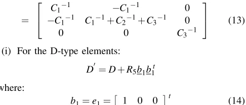
(13)
(i) For the D-type elements:
D0=D+R5b1b1t
where:
b1=e1= 1 0 0 t (14)
The above expresses the addition of resistor R5 to loop 1.
Hence, we have:
D0=
R1 −R1 0 −R1 R1+R2+R3 −R3
0 −R3 R3+R4
+
+
R5 0 0
0 0 0 0 0 0
=
=
R1+R5 −R1 0 −R1 R1+R2+R3 −R3
0 −R3 R3+R4
(15)
(i) For the T-type elements:
B0=B+L4b12b12t
where:
b12=e1−e2 (16)
The above expresses the addition of inductanceL4 to the
branch common to loops 1 and 2. Hence, we have:
B0=B+L4
1 −1 0
−1 1 0 0 0 0
=
L1 0 0
0 L2 0
0 0 L3
+
L4 −L4 0 −L4 L4 0
0 0 0
=
L1+L4 −L4 0 −L4 L2+L4 0
0 0 L3
(17) Summarizing, the transformed network is described by the corresponding matrices B0,C0,D0 , which lead to the new impedance matrix describes the above transformations, is given by:We(s) =s−1C0+sB0+D0.
Remark (2): The presence of an element of A−,T−,D−
type is expressed by an entry in the corresponding matrix
C,B,T respectively. In specific:
(a) If an element is present in the i-th loop (node), then its value is added in the i-th position of the respective matrix.
(b) If an element is common to the i-th and j-th loop then its value is added to the i-th and j-th loop diagonal entries, as well as subtracted from the (i,j)and (j,i) position of the corresponding matrix.
Proposition (1): Consider a network described by the triple C,B,D with natural operator W(s) =sB+s−1C+D
and corresponding companion pencil sF+G. Any network preserving cardinality transformation (combination of Type 1 and 2) may be represented by a triple C*,B*,D* and it results in a companion pencilsF0+G0 defined by:
sF0+G0=sF+G+
sB∗+D∗ C∗
0 0
=
= (sF+G) + (sH+K) (18)
Thus, structural transformations that preserve network cardi-nality are expressed as structured additive perturbations on the companion matrix pencil. This allows for the develop-ment of a framework for determinantal assigndevelop-ment of natural frequencies, which will be discussed next. A version of this problem was recently considered in [5].
IV. DETERMINANTAL ASSIGNMENT OF NATURAL FREQUENCIES
The mathematical formulation of the above problem is considered next. Note that det{sF0+G0} is expressed as:
sF0+G0
=det{s(F+H) + (G+K)}=
=det{[sF+G,I]
I sH+K
}=ϕ(s) (19)
A. Problem formulation
Given a square pencil sF+G such that F,G∈ℜnxn the problem to be examined is to investigate the solvability of the equation:
det{(sF+G) + (sH+K)}=φ(s) (20)
with respect to a pair of (H,K) structured matrices when
φ(s)is a given polynomial ofrdegree.
Notation: If m, n are two integers m6n, then Qm,n is
the set of lexicographically ordered sequences of m integers from the set{1,2, . . . ,n}andDnis any sequence of n integers
from{1,2, . . . ,n}with possible repetition and any order [10].
If X is an m×n matrix and r6min(m,n) then we shall denote byCr(X) the r-th compound matrix of X, which is
a matrix made up of allr×rminors ofX lexicographically ordered [10]. If r=min(m,n) thenCr(X)is a vector (row
or column respectively) referred to as the exterior product of rows (columns).
Using the above notation, we can define the Grassmann representative of the network and of the structural transfor-mations as:
g∧(F,G) =Cn[sF+G,I] =m(s)∧
g∧(H,K) =Cn
I sH+K
=h(s)∧ (21)
where the both multi-vectors (exterior products of rows , columns respectively) are coprime polynomial vectors and are referred to as the Grassmann representative of the net-work, g(F,G)∧and as the Grassmann representative of the structural changes, g(H,K)∧. Both of these multi-vectors are defined by maximal order minors of the corresponding matrices and the presence of an identity matrix implies that these vectors are coprime. Using the Binet-Cauchy Theorem [10], (20) leads to:
φ(s) =Cn[sF+G, I]Cn
I sH+K
=
=<h−(s)∧t,m(s)∧>=
∑
ω∈Qr,phω(s)mω(s) (22)
The above formulation is part of the general Determinantal Assignment Problems (DAP) family [6]. This problem is to solve the following equation with respect to polynomial matrix H(s): det[H(s)M(s)] = f(s) where M(s)∈Rp×r[s], r6p, is defined by the system,H(s)∈Rr×p[s], is defined the
design parameters and f(s)is a polynomial of an appropriate degree d. We should note [11] that all cases involving dynamics can be shifted fromH(s)toM(s), which, in turn, transforms the problem to a constant DAP which is defined by fM(s,H) =det
H M(s) = f(s), where H∈H an appropriate family. Note that in (22) < , > denotes inner product, ω = (i1, ...,ir)∈Qr,p and hω(s),mω(s) are the
coordinates ofh(s)∧,m(s)∧respectively, wherehω(s)is the r×r minor of H(s), which corresponds to the ω set of columns ofH(s)and thushω(s), is a multi-linear alternating function [10] of the entrieshi j(s)ofH(s). The difficulty for
the solution of DAP is mainly due to the multi-linear nature of the problem. The overall problem is reduced to a linear problem of zero assignment of polynomial combinants [6] defined by:
fM(s,k(s)) =h(s)t
p(s) =
∑
hi(s)mi(s) = f(s) ∈R[s] (23)and a standard multilinear problem, that is the solution of the exterior equation:
h1(s)∧...∧hr(s) =h−(s)∧= k(s)∈H (24)
whereH the family of solutions of (23).
Remark (3): Given that (H,K) are structured matrices
and(H,K)has a row of zeroes, g(H,K)∧has a number of zeroes resulting in possible fixed zeros inφ(s). Computing
the position of fixed zeroes in g(F,G)∧ is essential for determining the fixed frequencies of φ(s) under the given set of changes and this is considered next.
Definition(2): Sequences ω= (i1,i2, ...,in)∈Qn,2n
char-acterise the minors ofαω of g(H,K)∧. For such sequences
we define:
(a) The operation onω∈Qn,2n as:
π(ω) = (π(i1),π(i2), ...,π(in) = (j1, ...,jn)
where:
π(ik) =
i
k,ik≤n b
ik=ik−n,ik>n
(b) A sequence ω = (i1,i2, ...,in)∈Qn,2n is called degen-erate, if π(ω) = (j1,j2, ....,jn) has at least two equal
elements (i.e. jl= jk) and is called non-degenerate, if π(ω) = (j1,j2, ....,jn)has distinct elements.
(c) For a sequence ω∈Qn,2n which is non-degenerate we
define as thesign ofω,
sgn(ω) =σ(ω) =sign(j1,j2, ...,jn)and as thetrace of ω, the subset of the elements of π(ω) = (j1,j2...,jn)
which correspond to ik>n and thus is the set: hωi= (cik1,cik2, ...,cikn),i≤n.
Definition (3): Let QDn,2n, QnDn,2n be the ordered subjects of degenerate and non-degenerate of Qn,2n associated with the g(H,K)∧. We shall denote by ˜g(H,K)∧ the sub-vector of
g(H,K)∧ obtained by omitting all zero coordinates cor-responding to Qd
n,2n sequences (indices) and similarly by
˜
g(F,G)∧ the reduced dimension sub-vector of g(F,G)∧
derived by deleting the QDn,2n set of coordinates which will be referred to as the(H,K)-Grassmann representativeof the network. Note that:
φ(s) =g∧(F,G)t.g∧(H,K) =g˜∧(F,G)t.g˜∧(H,K) (26)
Remark (4): The polynomial vector ˜g∧(F,G) is not
nec-essarily coprime. The GCD of the elements of ˜g∧(F,G)
defines the(H,K)fixed zeros of the network [12].
Clearly, the formulation of the problem defined by (26) is similar to that of the decentralized DAP [6], [7] and can be treated using the exterior algebra, algebraic geometry approach developed in [6], [7]. For the special case of single parameter variations it has been shown that the problem is reduced to a standard root locus problem. The nature of the transformations characterises the properties of (H,K) and thus the respective assignment problem.
V. CONCLUSIONS
The paper has examined the problem of redesign of passive electric networks as a problem describing the structure evo-lution of systems linked to changes in the nature of topology, and values of the physical elements. Four different types of structural transformations have been defined and for the two which preserve the network cardinality it has been shown that these transformations are expressed as additive structured transformations on the companion pencil. The assignment of natural frequencies of the network was then considered and formulated as a spectrum assignment of matrix pencils under additive transformations. This problem may be studied within the framework of Determinantal Assignment introduced in [6], [7], [13]. Amongst the problems under investigation is the study of spectrum assignment under special families of (H,K) transformations, the characterisation of the fixed frequencies (if any) and the derivation of conditions for arbitrary assignment of such frequencies. For the cases where it is not possible to have arbitrary assignment we are investigating the possible enlargement of the transformations which may allow complete assignability.
REFERENCES
[1] N. Karcanias, “Structure evolving systems and control in integrated design,”Annual reviews in Control, 2008.
[2] ——, “Passive network redesign: System structure evolution,” City University London, Tech. Rep., 2011.
[3] S. Seshu and M. Reed, Linear Graphs and Electrical networks. Addison- Wesley, 1961.
[4] T. Berger, G. Halikias, and N. Karcanias, “Effects of dynamic and non-dynamic element changes in rlc networks,”International Journal of Circuit Theory and Applications, 2014.
[5] J. Leventides and N. Karcanias, “Zero assignment of matrix pencils by additive structured transformations,”Linear Algebra and its Appli-cations, vol. 431, no. 8, pp. 1380–1396, 2009.
[6] N. Karcanias and C. Giannakopoulos, “Grassmann invariants, almost zeros and the determinantal zero and pole assignment problem,”Int. J. Control, 1984.
[7] J.Leventides and N.Karcanias, “Global asymptotic linearisation of the pole placement map: A closed form solution for the constant output feedback problem,”Automatica, vol. 31, no. 9, pp. 1303–1309, 1995. [8] N. Karcanias, B. Laios, and C. Giannakopoulos, “The decentralised determinantal assignment problem: Fixed and almost modes and zeros,”Int. J. Control, vol. 48, pp. 129–147, 1988.
[9] F. R. Gantmacher,The Theory of Matrices. Chelsea, New York, 1959, vol. I and II.
[10] M. Marcus and H. Minc,A Survey of Matrix Theory and Matrix Inequalities. Allyn and Bacon, 1964.
[11] N. Karcanias, “Generalised resultants, dynamic polynomial combi-nants and the minimal design problem,”Int. J. Control, Special Issue for A.G.J. Macfarlane, vol. 86, pp. 1946–1964, 2013.
[12] M. Mitrouli and N. Karcanias, “Computation of the g.c.d. of poly-nomials using gaussian transformations and shifting,”Int. J. Control, vol. 58, pp. 11–228, 1993.