Design Coordination for Enabling Concurrent Engineering
G. Coates, W. Hills, R.I. Whitfield
Engineering Design Centre, University of Newcastle, Newcastle upon Tyne, NE1 7RU, United Kingdom
A.H.B. Duffy
CAD Centre, University of Strathclyde, Glasgow, G1 1XJ, United Kingdom
Abstract
Concurrent Engineering has been identified by many as an approach which can lead to improved product quality in less time at reduced cost. In this paper, we go further by recognising that coordination is a critical means by which Concurrent Engineering can be successfully achieved.
A design coordination methodology, generic in nature, is described which allows the maximum permissible design activity to be performed simultaneously. An implementation of the proposed methodology, termed the Design Coordination System, has been developed to assist the designer in performing computational analysis in a distributed computing environment. The Design Coordination System employs a collection of agents that act as members of a multi-functional team operating in a cooperative and coordinated manner in order to satisfy the objective of efficiently performing the design analysis. This involves agents seizing the opportunity to perform activities concurrently when and where possible.
1
Introduction
Ever increasing competition in the global marketplace has forced companies to investigate new methods of improving product quality, lowering costs and reducing the time taken to introduce new products. This competitiveness makes constant improvement and modernisation crucial to survival. Since the late 1980s in academia and the early 1990s in industry, Concurrent Engineering (CE) has been recognised as one such strategy for improving the design process. This involves performing as many activities in the design process simultaneously, enabled by cross-functional teams working cooperatively and effectively on separate aspects of the overall product development.
For a large engineering organisation, CE is seen by many as a requirement to achieve and sustain a competitive advantage in support of the development of high quality
products that can be produced efficiently. CE involves varying sized groups of expertise working simultaneously on different parts of an engineering project. These teams are independent but cannot work in isolation since communication must occur between them. For complex product development, CE not only needs multi-functional teams, but also requires communication between teams and effective coordination to integrate their efforts. Hence, a communication environment is required to allow effective sharing of information between teams and among team members of related development tasks.
Many issues have been identified as essential requirements with regard to ensuring that CE is effective when implemented and operated in a large engineering organisation or complex design process. The most prominent issues of CE are coordination, communication, cooperation (teamwork), integration, information sharing, multi-functional teams, planning, scheduling, discipline and productivity [1],[2],[3],[4],[5],[6].
In this paper, it is argued that coordination is the principal requirement for the successful implementation of CE. Coordination is expressed as the concept of the appropriate activities being performed, in a certain order, by a set of capable agents, in a fitting location, at a suitable time, in order to complete a set of tasks. That is, for the right reasons, at the right time, to meet the right requirements and give the right results [7].
2
Concurrent Engineering
becoming uncompetitive. Within industry, the response of significant amounts being invested in existing design procedures, therefore making it difficult to consider alternatives, will not ensure the companies success or existence in the long term.
CE is seen as one such approach that companies could employ if they are aiming to perform to their optimal potential. A forward thinking and progressive organisation will appreciate and understand the prominent issues of CE mentioned previously. Proper implementation and coordination of CE due to its systematic nature will ensure a more efficient and effective organisation. The size and nature of a business needs to be taken into account when deciding how, and to what extent, CE could be employed within the organisation.
Of the many definitions of CE, one of the most prominent is that given by Winner et al [8], and referred to by Karandikar et al [9], as “a systematic approach to the integrated, concurrent design of products and their related processes, including manufacturing and support. This approach is intended to cause the developer from the outset, to consider all elements of the product life cycle from conception through disposal including quality, cost, schedule and user requirements”. This definition is representative of many of those encountered in that the main emphasis is placed on its systematic approach to the design process as it reduces the design time and hence total design cost, which is one of the main considerations in the entire design process.
Duffy et al [1] state that design coordination is a vehicle for the realisation of CE. In addition, it is mentioned that while the main objective of CE is directed at considering aspects of design simultaneously, design coordination provides the means of integrating and controlling disparate activities. How design coordination can achieve objectives such as quality, cost, efficiency, etc. through simultaneity, integration and providence is also discussed.
Tan et al [2] identify coordination as the key design component for group problem solving and that CE needs integration, that is interactive sharing and use of information and knowledge between group members and also between groups.
McCord et al [3] define CE as multiple cross-functional teams, rather than cross-functional groups, working simultaneously on separate aspects of the overall development effort. Integration, coordination and information flow are identified as challenges of CE. A design structure matrix, as used by Steward [10], is used as a project modelling tool to illustrate the information flow pattern required across an organisation. This enables identification of those areas of the project in which coordination is needed most and integration is essential. It is also used to determine the communication patterns in an organisation and hence facilitates and ensures strong communication links where necessary. This matrix
representation is robust since small inaccuracies will not significantly affect the information flow, that is slight changes in dependencies between tasks will not affect the overall design of the system teams.
Tomiyama [4] identifies the critical issues of performing CE in industry as:
(a) constructing cross-functional teams that are focused on the target product,
(b) facilitate mutual communication among members of cross-functional teams,
(c) bringing traditionally later stages of the design process to the discussion table early,
(d) develop a computational infrastructure to facilitate (a), (b) and (c).
Gatenby et al [5] offers the basic elements of CE as cross-functional teams, concurrent product realisation process activities, incremental information sharing and use, integrated project management, early and continual supplier involvement and customer focus. The cross-functional teams act as a source of knowledge that ensures all considerations are incorporated into the product in the initial stages of development. The systematic implementation of CE is then described as: (a) benchmark and establish performance targets, (b) establish structure for breakthrough improvements, (c) characterise the current process,
(d) create target process, (e) verify all new processes,
(f) implement new processes across the entire set of production lines,
(g) measure results and continuously improve. Matta et al [6] describes a generic model for the CE task with three main subtasks. The first being the design subtask which relies on private knowledge and each designer generating some propositions to satisfy given requirements. Secondly, the argue subtask attempts to change other participants opinion by justifying the utility and the necessity of a proposition. The third subtask being where groups evaluate the integration of propositions. Conflicts arise when propositions do not satisfy participant’s needs. The primary task here is to detect and solve conflicts.
Without question, CE has become one of the more prominent contemporary strategies aimed at making an organisation more competitive in today’s aggressive commercial markets. The driving force behind this strategy is product quality and reliability improvement in order to gain customer confidence by meeting, and exceeding where possible, their requirements while reducing costs and the time taken to deliver the product. CE needs to be supported and sustained in order to achieve the long term benefits it offers. Inadequate implementation and coordination will result in the organisation failing to realise the benefits and give CE little opportunity of succeeding.
successful. Implementation may also be time-consuming and costly but the long term benefits of the full impact of the strategy are aimed at creating a stronger organisation. If only certain areas of an organisation utilise CE then the benefits may only be experienced locally and the business as a whole will not gain.
The applicability of CE must also be given careful consideration as it may not be plausible in a particular situation or even appropriate. CE may only be applicable in certain areas of the design process whereas the more traditional sequential approach may be required in other areas. Some activities should not be performed concurrently and if they are then there exists the risk of major re-work. Therefore, CE must be performed sensibly in that activities should only be carried out concurrently if it is realistic and advantageous to do so. Great effort should be taken to ensure that CE is utilised wherever possible providing the reasoning behind such a strategy aids the design process as a whole.
3
Requirement for Design Coordination
CE is concerned with the concept of performing activities simultaneously which are usually carried out sequentially. However, CE does not remove or shorten the duration of some sequential activities from the design process but brings together sequential activities and focuses on concurrent considerations in order to establish which activities can be performed simultaneously. Clearly, this concept of CE is attractive with obvious benefits and advantages. In order to be able to take advantage of concurrency at any level, an appropriate mechanism needs to be in place that enables any potential opportunities of simultaneity to be maximised and realised. Coordination is proposed as the principal key to such a mechanism.
Coordination, in an operational sense, with respect to completing tasks is concerned with five fundamental components: activity, agent, order, location, and time. Within any environment, in order to satisfy a particular requirement an activity needs to be performed so that the appropriate task can be completed. The activity needs to be specified which when performed will have the desired effect and complete the task. Therefore, careful consideration needs to be given to determine which activity is the most appropriate to carry out in order to do the task. To perform an activity, an agent, or agents, must carry out the required actions in order to complete a particular task. An agent can be considered as a resource and may be human, software or hardware. Essentially, an agent is an entity capable of performing some activity to do a given task. The correct choice of agent, or agents, will ensure that the activity is performed in the most suitable fashion and the task is completed satisfactorily. Since relationships can exist between tasks, there may be an optimal order in which activities should be performed to complete the tasks. Consideration to this fact will
assist in identifying those activities that can be performed concurrently and those that must be carried out sequentially. When an agent is performing an activity it may be appropriate to do so in a certain location. This consideration may be of particular importance and relevance when agents are working in the same team, or related teams, to complete the same task, or related tasks. For any activity, timeliness is usually of paramount importance. The time at which an activity is performed directly affects the completion of a task. In relation to the components identified, coordination can be expressed as “the concept of the appropriate activities being performed, in a certain order, by a set of capable agents, in a fitting location, at a suitable time, in order to complete a set of tasks”.
4
Agent Based Coordination Methodology
Coordination can be viewed as the decision making, controlling, modelling and planning/scheduling activities with respect to the design factors time, tasks, resources and aspects [1], [7]. The agent based coordination methodology described here embraces this high level concept in that it involves the coordination of tasks which aims to optimise the scheduling and planning of the design process with respect to the allocation and utilisation of available resources. The methodology incorporates an agent architecture in which each agent fulfils a particular role and performs several different activities. The behaviour of all agents is complimentary in that they assist other agents when necessary. Agents communicate by sending messages and take appropriate action when required.
[image:3.842.320.525.527.707.2]The seven types of agent described within the coordination methodology, and the communication links between them, are shown in Figure 1.
Figure 1 Agent Architecture RESOURCE
MONITOR
SCHEDULING AGENT
COORDINATION MANAGER
TASK MANAGER
INFORMATIONMANAGER
ACTIVITY DIRECTOR
In any application of the agent based coordination methodology, the number of certain agent types is fixed whereas others are dependent on factors such as the tasks to be completed in the design process and the available resources in the design environment. Only one Coordination Manager, Resource Manager and Scheduling Agent exist. The number of Information Managers is equivalent to the number of different tasks to be completed. The number of Task Managers is equal to the product of the number of tasks and the number of resources. Each resource being utilised is allocated a Resource Monitor and an Activity Director.
The Coordination Manager registers agents and provides an introduction service such that related agents can locate each other. The Resource Manager is responsible for ensuring that at all times optimal utilisation is made of the available resources in the design environment. When instructed by the Resource Manager, the Scheduling Agent invokes an optimisation package to create a schedule. Activity Directors act on this schedule by directing Task Managers to complete their tasks by performing the required activities. Prior to executing their tasks, Task Managers request concepts from their related Information Manager. Resource Monitors constantly review their associated resource and inform the Resource Manager of any change.
4.1 Coordination Manager
Initially, the Coordination Manager is central to all agent activity. In order for an agent to register its services, firstly it must send a message to the Coordination Manager. Information contained within this first communication relates to attributes of the agent. This information, which is dependent on agent type, is registered by the Coordination Manager in an address book. Once an agent’s attributes have been recorded, the Coordination Manager acknowledges the existence of the said agent. Subsequently, in the event of any one agent requiring particular information regarding another agent, the details can be obtained from the Coordination Manager. Knowledge of this information then enables the necessary agents to communicate directly, rather than via the Coordination Manager, and work cooperatively to perform their activities, complete their tasks, and achieve their goals. This feature of agents having the ability to communicate directly with any other agent allows efficient message passing, removes the problem of communication bottlenecks, and promotes coordination. Message passing is said to be efficient since communication only occurs when necessary between agents. The Coordination Manager facilitates the decentralisation of communication amongst agents. Consequently, message bottlenecks are avoided and communication can occur directly and concurrently between agents, rather than via some centralised agent. Coordination is promoted since the Coordination Manager can supply related agents with each others
details such that the agents can then work cooperatively as a team to meet the overall objective.
A number of agents request information from the Coordination Manager regarding other agents such that they can communicate directly and coordinate their activity. Specifically, each Task Manager requests the address of its related Information Manager. These agents are related if they are associated with the same task. If the Information Manager has registered, the Coordination Manager provides the Task Manager with the requested information. In the situation where the Information Manager has not yet registered, the Coordination Manager indicates to the Task Manager that it should request the information again at a later time. This period of time may be specified by the Coordination Manager. Similarly, the Scheduling Agent, Resource Monitor, and Activity Director agent types request the address of the Resource Manager. These requests are managed by the Coordination Manager in exactly the same manner as described with the Task Manager and Information Manager.
The Coordination Manager is also responsible for constructing an agent matrix, which is based on the representation of the design structure matrix [10]. The matrix contains information regarding dependencies between all registered agents and, hence, the communication links between them. In the event of the Coordination Manager becoming unavailable, the information contained within the agent matrix can be ascertained by its replacement. The replacement agent would be able to perform all duties originally performed by the Coordination Manager.
An agent replacement mechanism exists which enables any agent that becomes unavailable to be replaced such that the effectiveness of the agent community is not compromised and the performance of the coordination is not diminished. Unless, the agent that has become unavailable is the Coordination Manager, then it is the Coordination Manager who operates the agent replacement mechanism. New agents are seamlessly integrated into the society of agents with minimal impact on all other agents and the design process.
4.2 Information Manager
coordinates the concept from the previous task. That is, the concept may be removed from one resource and placed on another in preparation for the next activity to be performed. This procedure needs to be carried out after every activity is performed to avoid delays on any of the resources. Once all activities have been performed on a concept it is designated complete.
An Information Manager needs to be able to provide a specifically requested concept to the Task Manager while keeping a record of those concepts that have already been released and those pending. This is due to the order in which concepts are scheduled by the Scheduling Agent not necessarily being in ascending numerical order of concept identification number. Hence, a Task Manager may wish to request a specific concept rather than the next in the queue.
4.3 Task Manager
As with an Information Manager, a Task Manager is also associated with a particular task. A relationship exists between a Task Manager and Information Manager if they are associated with the same task. A Task Manager’s responsibilities include requesting concepts from its related Information Manager and subsequently supervising or performing the activity to complete the task on the concept on the assigned resource. Once a task has been completed by a Task Manager the related Information Manager coordinates the concept. Concepts continue to be requested from the Information Manager by the related Task Manager until all have been dispensed and each activity has been performed on them, and hence all tasks have been completed. That is, the design process is complete.
Task Managers need to be able to request a specific concept from their respective Information Managers so as to accommodate the ‘random’ order of proposed concept design within any given schedule as calculated by the Scheduling Agent. Hence, concept identification number is recorded which can be checked by the Activity Director prior to the activity being performed. An Activity Director is responsible for ensuring that the appropriate activities taking place on its associated resource are carried out in the correct order at the right time by the right Task Manager. Hence, a Task Manager will be instructed at the appropriate time to commence performing an activity on a particular concept by an Activity Director. Each Task Manager must act promptly when instructed to commence by an Activity Director. This prompt action will lead to the schedule being adhered to as closely as possible and the design process being completed in a near optimum time.
4.4 Resource Manager
As its name suggests, the Resource Manager is the agent responsible for managing the available resources. Functions of this agent include constructing a task matrix
and a resource matrix, again as used in [10]. The task matrix contains information such as dependencies between tasks and datum task durations. The Resource Manager uses the information held in this matrix to identify those activities that can be performed simultaneously such that the corresponding tasks that can be completed concurrently. The resource matrix contains a status flag and an efficiency measure for each resource within the design environment. A status flag is an indication of whether or not a resource is available for use. Efficiency is a relative measure of the speed of a resource. The Resource Manager updates the resource matrix when necessary following notification of a shift in a particular resource’s efficiency by the associated Resource Monitor.
On receiving notification from any of the Resource Monitors that their associated resource’s efficiency has fallen below a threshold level, the Resource Manager determines whether this change is significant enough to warrant an instruction to the Scheduling Agent to produce a new schedule. The threshold level will be particular to the design environment and is defined by the designer. In addition, the threshold level may vary with resources in the design environment. The Resource Manager decides whether or not the scheduling mechanism should be invoked as it may not always be appropriate to do so. Similarly, if a resource’s efficiency increases beyond a certain threshold level causing it to be more efficient than a resource currently being utilised in the design process then the Resource Manager should also consider requesting a new schedule. If the Resource Manager decides, that based on the information it has available, a new schedule is required then an instruction is sent to the Scheduling Agent to proceed in doing so.
Even if a schedule is followed to completion the remaining concepts will need to be scheduled.
In the situation where one of the resources is to be withdrawn from those being utilised then a new schedule needs to be calculated. Possible reasons for resource withdrawal could be reduced efficiency or unavailability. Only the remaining resources will be considered for selection within the new schedule. Similarly, if the efficiency of a resource not currently in use is increased then it may be sufficient to cause a new schedule to be calculated since it may be appropriate to replace a resource presently being utilised.
The Resource Manager oversees a resource pool in which resources can be selected for utilisation within the design process. Resources can be one of four states, namely active, idle, temporarily unavailable or redundant. If a resource is active or idle then it should be included within the resource pool. Temporarily unavailable and redundant resources are excluded from the resource pool. Active resources are those that are currently being used, or initially intended on being used, within the design process. Idle resources are those that are currently available for use within the design process but, due to their efficiency level, or the fact that their use would not assist in speeding up the design process, have not been selected for use. A temporarily unavailable resource is one which for some reason cannot currently be used but at some later time may become available. Resources classed as redundant are those that are inoperable for the duration of the design process. Resources are relegated from the resource pool if their state changes from active or idle to temporarily unavailable or redundant. A new schedule would only need to be calculated in the event where a resources state changes:
(a) from active to another state,
(b) to potentially active from another state.
A resource becomes potentially active if its efficiency becomes higher than a resource that is currently active. Resources are promoted to the resource pool if their state changes from temporarily unavailable to idle. If a resource becomes redundant then an event has occurred such that the resource will remain unavailable for the remaining lifetime of the design process. Redundant resources are relegated from the resource pool permanently.
A schedule will be calculated if a resource is being removed from or added to the design process. When a schedule is being calculated due to the removal of a resource from the design process, the Scheduling Agent should take into account all resources within the resource pool at that time, that is active and idle resources, with the exception of the active resource being removed. Conversely, a schedule being calculated due to the addition of a resource should take into account all resources currently in the resource pool. Resources within the resource pool should be ranked in order of efficiency
such that ifnresources are required to be used to perform the design process then the n most efficient resources should be selected.
4.5 Scheduling Agent
A Multi Criteria Genetic Algorithm [11] is utilised by the Scheduling Agent to facilitate the optimum utilisation of the available resources. The Scheduling Agent views the scheduling problem as the total design time, of a given number of tasks with interdependencies between them, should be minimised by assigning them to be performed on an optimum number of the most efficient resources to facilitate the design of a known number of concepts.
The Scheduling Agent prepares the information required for the Multi Criteria Genetic Algorithm (MCGA). This information is held in the task and resource matrices. Relationships between tasks, datum task durations, number of concepts to be designed, and available resources is information used by the Scheduling Agent in order to establish a schedule and, hence, an order to perform tasks on each concept. When instructed by the Resource Manager, the Scheduling Agent executes the MCGA to produce a Pareto optimal set of schedules. The Scheduling Agent then uses a prescribed criteria to select the most appropriate schedule from the set which enables the optimum utilisation of the available resources to be made. The Scheduling Agent notifies the Resource Manager when a new schedule has been produced. In addition, each Activity Director is notified of the schedule of tasks to take place on the resource to which it is associated. When a new schedule is produced, only those Activity Directors with a change to their current schedule need to be notified. It is conceivable that the task load and/or order may change on only a number of the resources being utilised rather than all of them. This feature of decomposing the global schedule into local schedules creates the opportunity for a more efficient approach to re-scheduling.
4.6 Resource Monitor
A Resource Monitor exists for each resource within the design environment. Each Resource Monitor continuously monitors and records the efficiency and status of its associated resource. If a Resource Monitor observes its associated resource’s efficiency deviate from the current value or the status change, then it will inform the Resource Manager of this fact and supply the latest statistics. This may result in the Resource Manager deciding to remove/add that particular resource from/to the design environment and request that a new schedule be calculated by the Scheduling Agent.
4.7 Activity Director
An Activity Director is responsible for directing the activities to be performed on its associated resource in order to complete the corresponding tasks. This agent also facilitates the operational coordination of the tasks and resources involved in the design process.
Each Activity Director must orchestrate the activities being performed on its associated resource. In particular, an Activity Director is responsible for instructing Task Managers to perform their associated activity on a particular concept on the associated resource in the appropriate order. A Task Manager will only be able to perform its associated activity if permission is given by the Activity Director. Once the Task Manager receives this instruction it proceeds to perform the activity on a given concept. On completion, the Task Manager informs the Activity Director that it has finished. The Activity Director then proceeds to instruct the next Task Manager in the local schedule to perform its activity on a particular concept, and so on.
If while an activity is being performed using a particular resource, the resource becomes unavailable, then the activity being performed will not be completed and, hence, the concept being designed will only be partially complete. A mechanism exists that enables this concept to be passed to a different resource such that the task can be completed. Since the Activity Director holds the identification number of the concept currently being designed using a particular task, in the event of the associated resource becoming unavailable, it can proceed to take corrective action. The concept being designed at the time a resource becomes unavailable, and the concepts next in the line of design using that resource, will be included in the schedule now needing to be produced by the Scheduling Agent. This schedule is calculated once the Resource Monitor has informed the Resource Manager of the unavailable resource which in turn informs the Scheduling Agent to re-schedule. This new schedule is then communicated in the normal manner as described earlier.
5
Design Coordination System
The agent based coordination methodology described has been implemented within the Design Coordination System (DCS). This CAD tool involves the coordination of analysis tools which aims to optimise the scheduling and planning of the computational analysis with respect to the allocation and utilisation of available processors. Agent communication is facilitated by an efficient message passing mechanism. Agents are able to send and receive messages and take appropriate action when required. An ontology is used in agent communication which defines a dictionary of terms that are meaningful and unambiguous.
One Coordination Manager, Resource Manager and Scheduling Agent operate within the DCS. The number of Information Managers is equivalent to the number of
different analysis tools. The number of Task Managers is equal to the product of the number of different analysis tools and the number of processors. Each processor being utilised by the DCS is allocated a Resource Monitor and an Activity Director.
With regard to the present state of implementation of the DCS, the Coordination Manager, Task Manager, Information Manager, Resource Manager, and Network Monitor agent types have been implemented. The functionality of each of these agent types is complete with respect to all other implemented agent types. The Scheduling Agent and Activity Director agent types have yet to be implemented within the DCS. The functionality of these two agent types is currently being developed as well as the additional functionality of the agents already implemented.
6
Application
The application considered involves the DCS being utilised within the Robust Concept Exploration (RCE) framework [12] to coordinate multiple instances of a single analysis tool. Due to the generic nature of the DCS, multiple analysis tools from any domain can be managed and coordinated. In this example, an analysis tool capable of producing a number of measurements for the seakeeping of a catamaran was used. After generating a number of design concepts, the RCE framework sequentually executes the analysis tool each time evaluating a different concept. Depending on the nature of the problem being considered, the time taken to perform the design analysis sequentially can be considerable and is usually attributed to the greatest proportion of the overall operation of the RCE framework. Benchmark results were obtained by employing the RCE framework in a Unix environment on one Ultra 1/170 machine, which has a single UltraSPARC processor. The benchmark execution times recorded were for the sequential execution of the analysis tool alone. Subsequently, the DCS was employed in the same Unix environment with the design analysis carried out on various combinations of Ultra 1/170 machines, namely 1, 2, 3, 4 and 5. DCS agent activity was performed on an Ultra 10 Workstation which has a single processor. Benchmark and DCS measurements were obtained from two cases involving 79 and 243 design concepts.
7
Results
The measure of performance used for the DCS was the elapsed time to compute the solution of a given number of design concepts. In an environment with dedicated processors, and based solely on computation time of the design concepts, as the number of processors
Benchmark results were obtained using a single Ultra 1/170 machine to sequentially compute 79 and 243 concepts for Case 1 and Case 2 respectively. The results presented in Table 1 were obtained by running the DCS
in comparable conditions for each operation with respect to processor utilisation. That is, it was ensured that other network usage was negligible.
Figures 2 and 3 indicate the total time taken for the family of agents operating within the DCS to perform their individual activities including the analysis tool execution duration for all design concepts being evaluated. Extrapolated benchmark execution times are also shown. The inverse relationship between the number of processors and computation time was used to obtain extrapolated results for 2, 3, 4 and 5 processors. Therefore, using n processors as opposed to 1 should result in a 100(n-1)/n% reduction in computational time. With respect to the extrapolated benchmark execution times, the assumption is made that for each combination of processors, all processors are working in parallel with an equal number of design concepts being evaluated sequentially on each of them.
[image:8.842.66.529.128.288.2]Figure 2 DCS & Benchmark (79 concepts)
Figure 3 DCS & Benchmark (243 concepts)
Clearly, and as expected, in both Figures 2 and 3 it can be seen that as the number of processors is increased, the DCS execution duration decreases. The results obtained using the DCS appear to exhibit the previously stated inverse relationship with respect to the number of processors utilised. The results indicate that the DCS is capable of achieving results in close proximity to the projected benchmark values for both Case 1 and Case 2. With respect to Case 1, the offset between the DCS and benchmark results vary from approximately 12% to 5.5%. For Case 2 the offset varies from approximately 14% to 4.5%. In both cases, the greatest difference exists when only a single processor is employed within the DCS. This particular scenario is unrealistic since there would be no requirement for the DCS if only one processor were available as its intended use is in a distributed computing environment. The need for operating the DCS can only be justified in the event of more than one processor being available. After discarding the single processor use of the DCS, it can be deduced
Number of Processors
n
(an)
100(n-1)/n
(%)
Case 1 (79 design concepts) Case 2 (243 design concepts)
(bn) (cn) (dn) (an-dn) (en) (fn) (gn) (an-gn)
100(1-cn/b1) 100(1-fn/e1)
Benchmark (secs)
DCS (secs)
Reduction (%)
Offset∆
(%)
Benchmark (secs)
DCS (secs)
Reduction (%)
Offset∆
(%)
1 0 885 990 -11.9 11.9 2725 3111 -14.2 14.2
2 50.0 - 506 42.8 7.2 - 1556 42.9 7.1
3 66.7 - 350 60.5 6.2 - 1070 60.7 6.0
4 75.0 - 270 69.5 5.5 - 804 70.5 4.5
5 80.0 - 230 74.0 6.0 - 670 75.4 4.6
0 600 1200 1800 2400 3000 3600
1 2 3 4 5
Design Coordination System Benchmark (extrapolated)
Ex
ecution T
ime (secs)
Number of Processors
0 200 400 600 800 1000 1200
1 2 3 4 5
Design Coordination System Benchmark (extrapolated)
Ex
ecution T
ime (secs)
Number of Processors
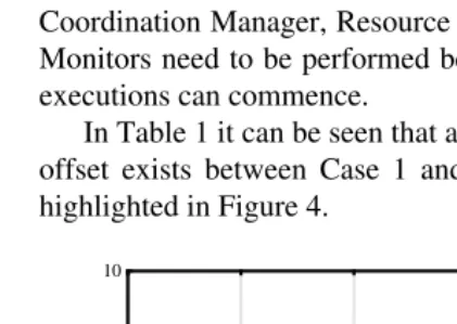
[image:8.842.63.280.512.669.2]from Table 1 that a relatively small offset range of 7.2% to 4.5% envelops both cases. This proportion of DCS operation is due to activities performed by agents excluding analysis tool executions by Task Managers. Prior to any analysis tool execution, the Information Manager is tasked with preparing and coordinating the various design concept models throughout the distributed design environment. Similarly, evaluated concepts need to be coordinated for subsequent use, in this instance within the RCE framework, between analysis tool executions. In addition, certain activities of the Coordination Manager, Resource Manager and Network Monitors need to be performed before any analysis tool executions can commence.
[image:9.842.65.276.290.439.2]In Table 1 it can be seen that a marginal difference in offset exists between Case 1 and 2. This difference is highlighted in Figure 4.
Figure 4 Offsets: Case 1 & Case 2
The discrepancy in offset between the two cases can be explained by the fact that the proportion of preparation and coordination activity performed by the Information Manager is less as a total percentage of the overall duration of the DCS in Case 2 than in Case 1. Approximately three times as many design concepts are evaluated in Case 2 as in Case 1 and therefore analysis tool computation time becomes more dominant. Hence, the greater the number of concepts being evaluated, the less the offset between the DCS and benchmark results.
8
Summary and Conclusions
The DCS has achieved significant reductions in the time taken to perform the computational analysis of a given number of design concepts within the RCE framework. Essentially, the time compression achieved by the DCS is inversely proportional to the number of processors utilised. As a result of significantly reducing the design analysis time, utilising the DCS has allowed the designer to perform a more comprehensive concept exploration of the design space. Consequently, the concept design selected was superior in terms of the designer’s nominated criteria.
It has been shown that the family of agents operating within the DCS can work cooperatively in a coordinated fashion with effective results. It is this ability of the agents to operate in a coordinated manner that permits the computational analysis time to be reduced by seizing the opportunity to perform activities concurrently. Simply committing greater resources to a particular part of the design process will not necessarily result in an appropriate reduction in the time to perform the tasks involved. It is the capacity to coordinate the activity performed by each of the team members, taking into account the available resources and knowledge of their roles and effects, and taking advantage of instances where concurrency is possible that enables a measured reduction in the duration of those activities to be achieved.
The current version of the DCS is being developed to promote even greater coordination within the context of the work described in this paper. This will be achieved with the introduction of additional agent types, namely the Scheduling Agent and Activity Director. The Scheduling Agent will enable optimal resources to be allocated dynamically with respect to the design analysis. The Activity Director will ensure that the right activity is performed in the right order on a resource. In addition, the DCS will be linked to an agent based Design Management System and an Integration framework in order to align coordinated activities with development plans, within an integrated environment.
Acknowledgments
The authors would like to express their thanks to the EPSRC and British Aerospace Military Aircraft who have supported this research.
References
[1] Duffy A.H.B., Andreasen M.M., MacCallum K.J. and Reijers L.N., “Design Coordination for Concurrent Engineering”, Journal of Engineering Design, Vol. 4, No. 4, 1993, pp. 251-265.
[2] Tan G.W., Hayes C.C.and Shaw M., “An Intelligent-Agent Framework for Concurrent Product Design and Planning”, IEEE Transactions of Engineering Management, Vol. 43, No. 3, August 1996, pp. 297-306. [3] McCord K.R. and Eppinger S.D., “Managing the
Integration Problem in Concurrent Engineering”. [4] Tomiyama T., “A Note on Research Directions of Design
Studies”, International Conference on Engineering Design, 1997, Vol. 3, pp. 29-34.
[5] Gatenby D.A., Lee P.M., Howard R.E., Hushyar K., Layendecker R. and Wesner J., “Concurrent Engineering: An Enabler for Fast, High-Quality Product Realization”, AT&T Technical Journal, 1994, pp. 34-47.
[6] Matta N. and Cointe C., “Concurrent Engineering and Conflict Management Guides”, International Conference on Engineering Design, 1997, Vol. 3, pp.761-766. [7] Andreasen, M.M., Duffy, A.H.B., MacCallum, K.J.,
Bowen, J., & Storm, T., “The Design Coordination Framework - key elements for effective product development”, Proceedings of the 1st International
0 2 4 6 8 10
2 3 4 5
Case 1 Case 2
∆
(%)
Engineering Design Debate, University of Strathclyde, Glasgow, UK. 23-24 September 1996.
[8] Winner R.I., Pennell J.P., Bertrand H.E. and Slusarczuk M.M.G., “The Role of Concurrent Engineering in Weapon Systems Acquisition”, IDA Report R-338, Institute of Defence Analysis, 1988.
[9] Karandikar H.M., Rao J. and Mistree F., “Sequential vs. Concurrent Formulations for the Synthesis of Engineering Designs”, American Society of Mechanical Engineers, 1991, DEVol. 322, Advances in Design Automation -Vol. 2, pp. 361-369.
[10] Steward, D.V., “The Design Structure System: A Method for Managing the Design of Complex Systems”, IEEE Transactions of Engineering Management, Vol. EM-28 (No.3), 1981, pp. 71-74.
[11] Todd D.S., ‘Multiple Criteria Genetic Algorithms in Engineering Design and Operation’, Ph.D. Thesis, University of Newcastle upon Tyne, October 1997. [12] Whitfield, R.I., Coates, G., & Hills, W., “Multi-Objective