Int. J. Electrochem. Sci., 13 (2018) 3006 – 3022, doi: 10.20964/2018.03.46
International Journal of
ELECTROCHEMICAL
SCIENCE
www.electrochemsci.org
Study of the Hole-Formation Process with Different Mask
Diameters via Through-Mask Electrochemical Machining
Hansong Li*, Chao Zhang, Guoqian Wang and Ningsong Qu
College of Mechanical and Electrical Engineering, Nanjing University of Aeronautics and Astronautics, 210016, P.R. China
*
E-mail address: hsli@nuaa.edu.cn
Received: 13 April 2017 / Accepted: 28 December 2017 / Published: 5 February 2018
Hole array structure components are widely used in the aviation industry and other industries. The plates used in such parts are thin, the number of holes is large, the arrangement is close, and the hole sizes are inconsistent. All these characteristics make the hole array structure components difficult to be fabricated in one process. The through-mask electrochemical machining technology has advantages in the machining of hole array structure components with difficult-to-machine materials. Suitable diameters of mask holes can be selected according to the size of the to-be-processed holes to complete the machining of hole array structure components. However, the appropriate choice of the mask diameter is still a problem. In this paper, based on the finite element model of through-mask electrochemical machining, simulations were conducted on the hole-formation process with five different mask diameters: 0.2 mm, 0.3 mm, 0.4 mm, 0.5 mm, and 0.6 mm. The hole-formation rules with different mask diameters were then obtained. To prove the simulation rules, the corresponding experimental study was performed using a 0.2-mm Ni-based superalloy plate. The simulation rules were verified, and a relationship figure between the diameters of fabricated holes and the machining time was obtained. Suitable masks can be selected according to this figure to fabricate holes with required diameters.
Keywords: through-mask electrochemical machining; finite element simulation; hole arrays with different diameters
1. INTRODUCTION
are inconsistent, and the materials of many parts are difficult-to-machine materials. All these issues make the fabrication of these micro-hole array structures challenging.
Many methods have been used to achieve good results on the machining of hole structure parts. Biermann and Kirschner investigated the small diameter single-lip deep hole drilling of Inconel 718, high surface quality and achieved tight dimensional and form tolerances [3]. B. Ghoshal and B. Bhattacharyya showed that both reversed taper and forward taper tools can be used for the generation of taper-less micro-features, i.e., boreholes by Electrochemical micromachining with the assistance of vibration of tool [4]. Hongyu Zhang used a newly developed laser drilling system to manufacture a series of micro-holes with circular, triangular, rectangular and rhombic shapes (diameter of 0.6 mm) on stainless steel 304 [5].
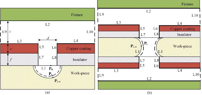
Through-mask electrochemical machining (TMECM) is a special machining technology based on the principle of electrochemical machining. TMECM obtains a similar pattern as that of the mask on a workpiece by using the mask to limit the erosion area [6]. Fig. 1 shows a schematic diagram of the TMECM. The mask is composed of a conductive layer and an insulating layer. d is the mask diameter. The mask is closely attached to the anode of the workpiece during the machining. An electric field is generated between the unshielded part of the workpiece and the two cathodes. Based on the electrochemical anodic dissolution mechanism, a pattern similar to the mask that meets the requirements is obtained. To reduce the hole taper, two masks are closely attached to the two surfaces of the workpiece, and the machining is conducted towards the centre. The electrolyte flows from the gap between masks and fixtures. The electrolysis products and heat produced in the machining are taken away to ensure the smooth progress of the machining.
Compared with other machining methods, TMECM has the advantages of no tool wear and no heat-affected layer [7]. Compared with the standard through-mask ECM using the photolithography process, the TMECM proposed in this paper has the advantages of short machining cycle, simple equipment and reusable mask [8,9].
Volgin established a mathematical model of the through-mask ECM by studying the initial machining current density distribution under different mask heights and different mask opening widths; the model is useful for TMECM [10]. Guoqian Wang and Hansong Li obtained high-quality hole array structure components by changing the opening angle of the through-mask ECM mask and the flow characteristics of the flow field [11,12]. Ningsong Qu successfully prepared micro-dimple arrays on the inner surface of a cylinder using the dry-film photoresist ECM method [13]. P. Kern prepared 100 μm hole arrays on a titanium alloy using the through-mask ECM method [14].
However, the difficulty of machining hole array structure components using TMECM method lies in the choice of the appropriate mask diameter that ensures the machined holes meets the machining requirements while taking into account the machining efficiency. In addition, for structural parts with different hole diameters, different masks are typically used to process holes with different diameters at different sessions. This process is both time and labour consuming and increases the position error between holes.
[image:3.596.137.454.148.357.2]
superalloy plate with different mask diameters. Moreover, the relationship figure between the machined holes with different mask diameters and the machining time was obtained. A suitable mask diameter can be selected to fabricate required hole arrays using this figure.
Figure 1. The schematic diagram of TMECM.
2. MATHEMATICAL MODEL OF ANODE CORROSION
The TMECM process is generally divided into two stages. The main direction of corrosion is along the hole depth direction before the plate is punched through, accompanied by radial corrosion. This stage can be called the punch-hole stage. A hole with a large taper will be formed when the punch hole stage is completed. Next, the process enters the second stage, which involves radial corrosion. This stage can be called the enlarge-hole stage. This stage can effectively decrease the taper of the hole. The enlarge-hole stage has an important impact on the hole surface morphology and surface quality [15].
The spacing between holes on the mask is large, and each hole can be regarded as an independent fabrication area. The electric fields of the upper and lower mask are independent before the plate is punched through in the punch-hole stage. The single-sided machining simulation is used to avoid the interaction effect of nodes moving. As shown in Fig. 2-a, c is the distance between the fixture and the mask, e is the conductive layer thickness, and f is the insulating layer thickness. When the hole depth reaches half of the workpiece thickness, the hole morphology is extracted. The process enters the enlarge-hole stage, and a symmetrical process is implemented. As shown in Fig. 2-b, the enlarge-hole stage is simulated using the double-sided machining model.
reaction at the electrode interface) on the machining gap electric field distribution is ignored. The external electric field at both ends of the workpiece at this time is considered as a stable electric field, with the following assumptions [16-18]:
(1) The content of the solid phase electrolytic product in the electrolyte is relatively small and does not substantially affect the electrical conductivity and fluid properties of the electrolyte.
(2) The overpotential caused by other factors at the electrode interface does not substantially affect the distribution of the inter-electrode potentials. Therefore, the cathode and the anode are considered as equipotential surfaces.
[image:4.596.90.507.252.449.2](3) The ‘fringe effect’ of the current is ignored.
Figure 2. The finite element model of a single hole electric field. (a) The finite element model of the punch-hole electric field; (b) the finite element model of the enlarge-hole electric field.
It is assumed that the conductivity of the electrolyte in the machining gap is constant and isotropic. Under this condition, the potential distribution in the electrochemical machining gap region conforms to Laplace’s equation:
(2.1) Where x and y are the coordinate values of each point in the machining area; is the potential for each point. The conductive layer and fixture are connected to the cathode of the power supply, and the workpiece (anode) is connected to the anode of the power supply. The surfaces of the cathode and the anode form equipotential surfaces. Thus, the bipolar boundary potential satisfies the following boundary conditions:
Cathode surface:
(2.2) Anode surface:
Where are the cathode surface potentials, is the anode surface potential, and U is the machining voltage. Since the boundary of the entire model area is closed, the boundary electric field distribution satisfies the following conditions:
(2.4) Where n represents the normal vector of the boundary; are the potential values of the corresponding boundaries. In the case of satisfying all the model’s boundary conditions (2.2) - (2.4), the Laplace’s equation (2.1) is solved to obtain the field intensity distribution throughout the model.
The following equations can be obtained from the relevant electric field theory and the principle of electrochemical machining.
(2.5) (2.6)
Where i is the current density, C is the conductivity of the electrolyte, E is the electric field intensity; v is the workpiece corrosion rate, and is current efficiency.
At the beginning of machining, take an arbitrary point P0 on the workpiece. The coordinates of this point are (x0,y0). With the progress of electrochemical machining, P0 has corrosion in both the x and y directions after a period of time t. At this point, the coordinates are Pi(xi,yi). After another short
time period , the coordinates become Pi+1(xi+1, yi+1). The following can be obtained from equations
(2.5) and (2.6):
(2.7)
Where Ex and Eyare the electric field intensity components at point P in the x and y directions, respectively. According to Equation (2.7), based on the parametric design language APDL of ANSYS, the machining process of the workpiece was simulated by using the electric field analysis module. The workpiece corrosion process was obtained using the iteration method.
The hole-formation process is simulated with five different mask diameters: 0.2 mm, 0.3 mm, 0.4 mm, 0.5 mm, and 0.6 mm. The machined hole with mask diameter of 0.2 mm is referred to as H2, the machined hole with mask diameter of 0.3 mm is referred to as H3, and so on. The machined hole with mask diameter of 0.6 mm is referred to as H6. Table 1 shows the parameters for the APDL electric field simulation.
Table 1. Simulated conditions of APDL
The thickness of the workpiece (mm) 0.2
The simulation voltage (V) Electrical conductivity (S/mm)
35 0.0125 Actual volume electrochemical equivalent (mm3/(A·min)) 1 The distance between the fixture and the mask c (mm) 1
Conductive layer thickness e (mm) 0.1
3. SIMULATIONS OF THE HOLE-FORMATION PROCESS
3.1 Punch-hole stage
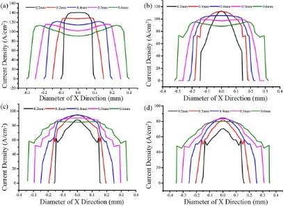
Fig. 3 shows the current density distribution of the simulated hole in the punch-hole stage. Fig. 3-a shows the current density distribution of the hole surface when the machining time is 1 s. From this figure, the maximum value of the current density is in the following order: H2>H3>H4>H5>H6. Obviously, in the next short period of time, the corrosion rate of H2 is the fastest in the Y direction, followed by H3, and so on, and H6 is the slowest. Fig. 3-b shows the current density distribution of the hole surface when the machining time is 5 s. Compared with Fig. 3-a, the current density of fabricated hole surface is reduced. In addition, the decrease of current density is different with different mask diameters. At this time the maximum value of current density is in the following order:
H2≈H3>H4>H5 >H6. It can be seen that the corrosion rate in the Y direction for the next short period of time is in the order of H2≈H3>H4>H5>H6. Figs. 3-c and 3-d show that, as the machining time reaches 10 s, the current density of the fabricated hole surface is further reduced, and the maximum current density at this time is in the order of H3≈H4>H5>H2>H6.When the machining time is 15 s, the maximum value of current density is in the following order: H4>H5>H3>H6>H2.
Figure 3. Current density distribution of the fabricated holes by using different diameters of mask holes. (a) Machining time of 1 s. (b) Machining time of 5 s. (c) Machining time of 10 s. (d) Machining time of 15 s.
[image:6.596.96.506.366.662.2]
is in the following order: H2>H3>H4>H5>H6. Fig. 4-b shows the morphological changes of the simulated hole with a machining time of 10 s. It can be seen that the corrosion amount in the Y direction is still in the order of H2>H3>H4>H5>H6. Fig. 4-c shows that when the machining time reaches 15 s, the corrosion amount in the Y direction is in the following order: H2> H3> H4> H5>
H6. However, the corrosion amount of H3 is almost the same with H2. Fig. 4-d shows that when the machining time reaches 20 s, H2, H3, H4, and H5 have entered the enlarge-hole stage, while H6 is still in the punch-hole stage.
Figure 4. Morphologies of the fabricated holes by using different diameters of mask hole. (a) Machining time of 5 s. (b) Machining time of 10 s. (c) Machining time of 15 s. (d) Machining time of 20 s.
[image:7.596.77.504.193.511.2]
Based on the above description, it can be seen that, with the increase of machining time, the smaller the mask hole, the faster the surface current density decreases, and the lower Y-direction corrosion rate. This result is consistent with the result of Volgin [10] because the small mask diameter has the effect of restraining the electric field. Early in the punch-hole stage, the workpiece is relatively close to the cathode, and the opening of small diameter mask is small. Thus, small diameter mask plays the role of concentrating the electric field, which improves the workpiece surface current density and the corrosion rate. Because the large diameter mask has large openings, the electric field cannot be concentrated. With the axial and radial corrosion of the hole, the distance between the workpiece surface and the cathode increases. The opening of the small diameter mask is smaller than that of the large diameter mask; thus, it shields more electric fields and leads to the sharp decrease of hole surface current density. These phenomena lead to the decrease in the corrosion rate.
[image:8.596.158.439.358.560.2]In addition, when the mask opening is wider because of the tip effect of the electric field itself, the current density of the hole at both ends is greater than that in the centre, causinga bulge to form at the bottom of the hole. The bulge, which is also called an ‘island’, also appeared in the process of forming a micro-dimple [6].
Figure 5. The difference values between mask diameters of 0.2 mm and 0.6 mm.
Table 2. The punch-hole time of fabricated holes with different mask diameters.
Fabricated holes with different mask diameter (mm)
Punch-hole time (s)
H2 18
17.4 18 19.2 20.4
[image:8.596.135.456.635.738.2]
When holes are punched through, the process enters the enlarge-hole stage. According to the simulation, the punch-hole time of fabricated holes with different mask diameters is shown in Table 2. The punch time of H2 is 18 s. The punch time of H3 is 17.4 s. The punch time of H4 is 18 s. The punch time of H5 is 19.2 s. The punch time of H6 is 20.4 s.
3.2 Enlarge-hole stage
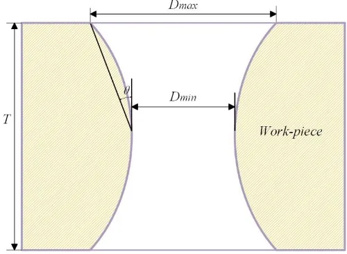
The hole taper is an important indicator of the hole quality. Fig. 6 shows the enlarge-hole process, showing a schematic diagram of the hole taper. The taper arctan(Dmax Dmin)
T
, where Dout
is the maximum diameter of the hole, Dmin is the minimum diameter of the hole, and T is the workpiece thickness.
Figure 6. Taper angle of the fabricated hole.
Fig. 7 shows the simulated morphological changes of holes with different mask diameters in the enlarge-hole stage. Fig. 8 shows the current density distribution of holes in the enlarge-hole stage. Fig. 7-a reveals that all H2, H3, H4, H5, and H6 enter the enlarge-hole stage at machining time of 25 s, forming hole morphologies with a large taper. Fig. 8-a shows the hole surface current density distribution at the machining time of 25 s. The figure shows that the current density is concentrated in the middle of the sidewall. The current densities in both ends of the sidewall are relatively small. Therefore, the corrosion rate of the hole in the middle is relatively high in the next short period of time; as a result, the hole taper decreases rapidly. In addition, the maximum current density is in the order of H6>H5>H4>H3>H2; as a result, the corrosion rate is in the following order:
H6>H5>H4>H3>H2.
Figs. 7-b, 7-c and 7-d show that the tapers of H6, H5, and H4 are relatively low at the machining time of 30 s, whereas the tapers of H3 and H2 are still large. When the machining time reaches 40 s, the tapers of H6, H5, and H4 are close to 0, the taper of H3 is also very small, and H2
[image:9.596.175.425.270.453.2]
times between 30 s and 50 s. The distribution is more uniform with the increase of machining time. The current density at the same time is in the following order: H6>H5>H4>H3>H2.
The decrease rate of the small hole taper is found to become slower. Moreover, the change rate of the fabricated hole taper for the large diameter mask is always higher than that of the small diameter mask. At longer simulated machining times, the hole taper is no longer changed, and only simple radial corrosion exists, further increasing the hole diameter. Thus, the time when the hole morphology no longer changes can be used as an indicator for the completion of the hole-formation process.
The completion of the hole-formation time of fabricated holes with different mask diameters according to the simulation is shown in Table 3. From the table, the completion of hole-formation time of H2 is 51.6 s, H3 is 45.6 s, H4 is 42.6 s, H5 is 42 s and H6 is 40.8 s. This result is important for fabricating small holes with different mask diameters at the same time; otherwise, one type of hole may meet the requirements while the taper of others may still be in a changing state.
[image:10.596.55.544.306.683.2][image:11.596.120.480.72.365.2]
Figure 8. Current density distribution of the fabricated holes using different diameters of the mask holes. (a) Machining time of 25 s. (b) Machining time of 30 s. (c) Machining time of 40 s. (d) Machining time of 50 s.
Table 3. Completion of hole-formation time of fabricated holes with different mask diameters
Fabricated holes with different mask diameters (mm)
Completion of hole-formation time (s)
H2 H3 H4 H5 H6
51.6 45.6 42.6 42 40.8
4. RESULTS AND DISCUSSION
[image:11.596.110.488.478.581.2][image:12.596.145.444.311.535.2]
layer and a 0.2-mm epoxy resin insulation layer. Fig. 10 shows a hole array with different mask diameters. The diameters from top to bottom are 0.2 mm, 0.3 mm, 0.4 mm, 0.5 mm, and 0.6 mm. There are 15 holes for each row.
Table 4. Machining parameters for the experiments.
Voltage (V) 35
Pulsed power frequency (Hz) 400
Pulse power duty ratio (%) 20
Electrolyte concentration (wt.%) 10%NaNO3 aq
Electrolyte temperature (◦C) 35
Electrolyte pressure (MPa) 0.4
Workpiece material Ni-based superalloy
Thickness of workpiece (mm) 0.2
Figure 9. Schematic diagram of the experimental system.
[image:12.596.207.385.595.737.2]
The experimentally fabricated small holes were observed using a MicroXAM 3D Profile instrument and a microscope (STM7, OLYMPUS, Japan), and the obtained data were processed using the Origin8.0 software.
To obtain hole corrosion depth in the Y direction during the punch hole stage, the profiles of the hole morphology are measured by using MicroXAM 3D Profile, as shown in Fig. 11-a. According to the profiles of the hole morphology, the hole corrosion depth data of the Y direction are shown in Fig. 11-b. Because the holes are made using the double-side machining process, the depth of the hole corrosion is two times the of hole morphology measurement data. The Fig. 11 shows that, when the machining time is 5 s, the punch hole depth is in the order of H2>H3>H6≈H5>H4, and the hole depth of H4 is more than 100 μm. When the machining time reaches 10 s, the hole depths of H6 and H5 are greater than those of H2 and H3. When the machining time reaches 15 s, the hole depths of H4 are more than those of H3 and H2 and increased to the third place. As the machining continues, some holes are punched through. When the machining time reaches 20 s, H6 has 15 holes that were punched through, H5 has 15, H4 has 8, and H3 has 10, whereas H2 has only 3 holes that were punched through, as shown in Fig. 12. Clearly, the corrosion rate decreases as the machining time increases, and the decrease of smaller mask diameter is faster than that of the large mask diameter. When the machining time reaches 25 s, all the holes were punched through. Fig. 13-a shows the images of the fabricated holes obtained using a microscope. Fig. 13-b shows the taper data of holes with different mask diameters. According to Fig. 13, the decrease rate of the hole taper is lower with the increase of machining time. If the hole taper below 5 degrees is regarded as a sign of hole-formation, then the completion time of hole-formation of H5 and H6 is 50 s, H4 is 60 s, H3 is 70 s, and H2 is 80 s. When the test and measurement errors are ignored, in a certain range, the hole taper fabricated by large mask diameter is found to decrease faster than that of the small mask diameter.
[image:13.596.81.511.504.680.2]
Figure 12. Images of the machined hole-array at the machining time of 20 s.
Figure 13. Angle of the fabricated holes at different machining times. (a) The microscopic images of the fabricated holes. (b) The taper data of holes with different mask diameters.
[image:14.596.102.520.349.566.2][image:15.596.160.438.70.347.2]
Figure 14. Images of machined hole-array (a) Photograph of the array holes; (b) microscope image of a single hole.
Figure 15. Diameters of the fabricated holes with different machining times.
[image:15.596.162.433.423.622.2]
machining time is 100 s. The average diameters of these five different holes are 540.3 μm, 694.2 μm, 820.1 μm, 985.7 μm, and 1110.9 μm. The hole diameter deviation is less than 50 μm, and the taper is less than 5 °.
Fig. 15 shows the relationship between the achievable qualified holes and the machining time for different mask diameters. According to the change of the diameters, five curves with decreasing slope are fitted. The fabrication range of these curves includes 500 μm to 1350 μm.
[image:16.596.77.520.270.358.2]For hole array structures with single diameter, suitable mask diameter and machining time can be selected to fabricate the required hole diameter according to the fitted relationship curve between the hole diameter and the machining time.
Table 5. The actual and linear interpolated diameters for different through-mask fabricated holes.
Mask diameter (mm) Linear interpolated size (μm) Actual size (μm) Error (μm)
0.25 617.2 605.5 11.7
0.35 757.1 776.5 19.4
0.45 902.9 928.0 25.1
0.55 1048.3 1064.6 16.1
For hole array structures with different diameters, a suitable machining time can be found from the above figure to meet the hole fabrication requirements for different mask diameters at the same time. For some structures that are not shown on the curves, the linear interpolation method can be used to estimate the required mask diameters. Thus, the machining of hole array with different diameters can be completed in a single fabrication. Table 5 compared the linear interpolated and the actual fabricated diameters when the machining time is 100 s. The errors between actual and linear interpolated diameters for four through-mask fabricated holes are 11.7 μm, 19.4 μm, 25.1 μm and 16.1 μm.
5. CONCLUSIONS
In this paper, the theory of TMECM was introduced, and the influences of different mask diameters on the hole-formation process were studied. In addition, experiments were designed and analysed. Based on the results, the following conclusions are drawn.
1. According to the finite element electric field model of through-mask electrolysis, the punch-hole stage and enlarge-punch-hole stage in the punch-hole-formation process were studied. Early in the punch-punch-hole stage, the corrosion rate of small diameter mask is higher than that of the large diameter mask. With the increase of machining depth, the decrease of corrosion rate for a small diameter mask is faster than that of a large diameter mask. At this time, the corrosion rate of the large diameter mask may exceed the small diameter mask. In the enlarge-hole stage, the corrosion rate of the large diameter mask is always higher than that of the small diameter mask.
using a mask diameter of 0.2 mm, it takes 70 s using a mask diameter of 0.3 mm, it takes 60 s using a mask diameter of 0.4 mm, and it takes 50 s using mask diameters of 0.5 mm and 0.6 mm. Within a certain range, the larger the mask diameter, the shorter the hole-formation time.
3. The hole machining times for 0.2-mm Ni-based superalloy plate are provided. Suitable mask diameters and machining times can be selected according to the required hole diameters.
References
1. M.D. Nguyen, Int. J. Mach. Tool. Manu., 54 (2012) 55.
2. J. Pattavanitch, S. Hinduja, CIRP Ann.-Manuf. Tech., 61 (2012) 199. 3. D. Biermann, M. Kirschner, J. Manuf. Process, 20 (2015) 332. 4. B. Ghoshal, B. Bhattacharyya, Precis. Eng., 38 (2014) 127.
5. H. Zhang, J. Di, M, Zhou, Y. Yan and R. Wang, Appl. Phys. A: Mater. Sci. Process., 119 (2015) 745.
6. X.L. Chen, N.S. Qu, H.S. Li and Z.N. Guo, Precis. Eng., 39 (2015) 204. 7. D. Landolt, PF. Chauvy and O. Zinger, Electrochim. Acta, 48 (2003) 3185.
8. D. Zhu, N.S. Qu, H.S. Li, D.L. Li and S.Q. Qian, CIRP Ann.-Manuf. Tech., 58 (2009) 177. 9. N.S. Qu, X.F. Zhang, X.L. Chen, H.S. Li and D. Zhu, J. Mater. Process. Tech., 218 (2015) 71. 10. V.M. Volgin, T.B. Kabanova and A.D. Davydov, J. Appl. Electrochem., 45 (2015) 679. 11. G.Q. Wang, H.S. Li, N.S. Qu and D. Zhu, J. Manuf. Process., 25 (2017) 246.
12. H.S. Li, G.Q. Wang, X. Zheng and Y.B. Zeng, Adv. Mech. Eng., 7 (2014) 704843. 13. N.S. Qu, X.L. Chen, H.S. Li and Y.B. Zeng, Chinese J. Aeronaut., 27 (2014) 1030. 14. P. Kern, J. Veh1 and J. Michler, J. Micromech. Microeng., 17 (2007) 1168.
15. G.Q. Wang, H.S. Li, N.S. Qu and D. Zhu, J. Mater. Process. Tech., 234 (2016) 95. 16. R.V. Shenoy, M. Date and L.T. Romankiw, J. Electrochem. Soc., 143 (1996) 2305.
17. D. Zhu, N.S. Qu, H.S. Li, Y.B. Zeng, D.L. Li and S.Q. Q, CIRP Ann.-Manuf. Tech., 58 (2009) 177.
18. D. Zhu, Y.B. Zeng, CIRP Ann.-Manuf. Tech., 57 (2008) 227.