Int. J. Electrochem. Sci., 13 (2018) 3091 – 3106, doi: 10.20964/2018.03.153
International Journal of
ELECTROCHEMICAL
SCIENCE
www.electrochemsci.org
Nitrogen-doped Hollow Carbon Hemisphere Supporting PtSn
Nanoparticles with a Tunable Microstructure to Effectively
Improve Electrocatalytic Performance for Ethanol Oxidation
Xiaofen Wu1, Hao Qin2, Yanting Li2, Lili wang2,*, Yanni Shen2, Jiajun Tang1, Xiaofeng Wang3, Jiahao Ren2, Bing Wang2,*
1
School of Materials science and Engineering and Tianjin Key Laboratory of Fiber, Tianjin Polytechnic University, Tianjin 300387, China
2
State Key Laboratory of Separation Membranes and Membrane Processes, School of Environment and Chemical Engineering, Tianjin Polytechnic University, 399 Binshui West Road, Tianjin 300387, P. R. China
3
State Key Laboratory of Inorganic Synthesis and Preparative Chemistry, College of Chemistry, Jilin University, Changchun 130012, P. R. China
*
E-mail: [email protected], [email protected]
Received: 23 October 2017 / Accepted: 20 December 2017 / Published: 5 February 2018
Herein, a series of nitrogen-doped hollow carbon hemispheres (HCHs) were prepared using silica as template, asphalt and urea as carbon and nitrogen source. The obtained different nitrogen content HCHs were then applied for supports of PtSn nanoparticles catalyst for ethanol oxidation in acid media. The PtSn nanoparticles were evenly deposited on HCHs with a narrow size distribution. Tunable size and distribution of the PtSn catalysts were obtained by adjusting nirtrogen content. Among all the synthesized PtSn catalysts, nitrogen content was the highest when the mass ratio of asphalt to urea was 2:1. The electrochemical analysis illustrated that the catalyst with highest nirtrogen content presented best electrocatalytic activity and stability for ethanol oxidation in acid media, providing that the HCHs with unique hollow structure and optimum nitrogen doping content can effectively improve the ethanol electrocatalytic activity and stability.
Keywords: Hollow carbon hemisphere, Nitrogen-doped, PtSn, Ethanol oxidation.
1. INTRODUCTION
containing hydrogen such as ethanol, methanol, ethylene glycol and glycerol as fuel could be good substitutes owing to their high energy density, low cost and convenient storage [3]. Amongst various candidates, ethanol as fuel can be a promising substitute for fossil fuels because ethanol as power source has the advantages of high energy density (8.0 kWh·kg-1
), pollution free and renewable [4, 5]. Nevertheless, ethanol oxidation reaction (EOR) undergoes slow electrooxidation kinetics because of generating acetic acid, acetaldehyde, and carbon monoxide (COad) during the ethanol oxidation [6]. The catalyzer of EOR requires high overpotential to make the strong C-C bond breaking from ethanol. Pt catalyst is considered the most commonly used electrocatalyst for the EOR [7]. However pure Pt is expensive and extremely easy to cause poisoning [8]. Hence the commercial development of ethanol oxidation was largely restricted. Several researches have found Pt-based alloyed catalysts are more resistant to the poisoning than Pt-alone due to the modification of the electronic structure of Pt atom [7]. For instance, some Pt-based bimetallic materials (NPs: PtSn, PtCu, PtNi, and PtAu, etc) could weaken the CO poisoning and improve catalytic activity [9]. It is widely accepted that PtSn catalyst is one of the best catalyst for the EOR compared with other Pt-based binary catalysts [6]. The presence of Sn on Pt electrodes favors the C-C bond breaking at low overpotentials and the generation of acetaldehyde and acetic acid at high overpotentials [10]. It was found that Pt: Sn atomic ratio of 1:3 is the best ratio for EOR [11].
Moreover, catalyst’s performance is partly determined by the properties of support and interaction between support and metal nanoparticles, therefore, it is neccessary to develope an appropriate supporting material to enhance the performance of the catalysts. In recent years, the different morphology and structure carbon-based materials, such as carbon nanofiber [12], carbon sheet [13], graphene [14], carbon nanotubes [15], mesoporous carbon [16] and hollow carbon spheres [17] have been synthesized due to their large surface area, chemically inertia, high electronic conductivity and low cost. They have been investigated for many applications such as supercapacitors [16], lithium ion battery [18] and catalyst support [13] etc. Hollow carbon hemispheres (HCHs) is a prevailing carbon support material for the catalysts due to their unique opening three-dimensional channels, a large number of micropores and mesopores, high electrochemical active surface area etc, which are favorable to well disperse metal nanoparticles and the molecules transfer. Furthermore, the performance of carbon support depends not only on its morphology but also on doped heteroatom in its structure. Particularly, some nitrogen-doped carbon materials exhibit excellent electrocatalytic activity because electron-rich nitrogen doping can modify the surface structure of carbon materials [14]. Several studies have suggested nitrogen atoms can provide more active sites on carbon material surface for metal nanoparticle deposition [19].
effectively increase the electrocatalytic oxidation of ethanol. Furthermore, various characterizations such as SEM, EDX, TEM, HR-TEM, XRD and XPS analysis were used to investigate the relationship between the microstructure and electrocatalytic performance of the catalysts.
2. EXPERIMENTAL MATERIALS AND METHODS
2.1. Materials
Tetraethoxysilane (TEOS), ethanol, ammonia, asphalt, urea, THF (Tetrahydrofuran), NaOH (Sodium hydroxide), HNO3 (Nitric acid), H2PtCl6·6H2O (chloroplatinic acid hexahydrate),
SnCl2·2H2O (Tin protochloride dihydrate), glycol, H2SO4 (Concentrated sulfuric acid, 98 wt%) were
purchased from Sinopharm Chemical Reagent Co., Ltd., the carbon black powder (Vulcan XC-72R) was purchased from Cabot Corporation, Nafion (5%) was purchased from Aldrich, and all the reagents were of analytical grade.
2.2. Catalysts preparation
Scheme 1. Schematic diagrams illustrate the preparation process of PtSn/HCH-Nx.
The preparation strategy is illustrated in Scheme 1. The silica template was first prepared by improved Stöber method [20]. The composite of carbon source, nirtrogen source and silica template (C-N/SiO2) was obtained by using silica spheres as templete, asphat and urea as carbon and nitrogen
sources. Then the C-N/SiO2 composite was carbonized and silica was removed. Finally, the
2.2.1. Preparation of the silica spheres
Firstly, aqueous ammonia (7 mL) as the catalyst was added in the mixture of ethanol (100 mL) and water (2 mL), then the mixture was heated to 35 oC to form a homogeneous and clear solution under stirring. Afterward, TEOS (8 mL) was droppeded slowly into the mixture in oil bath at 35 oC for 8 h, and then the white solid slurries were centrifuged, washed and dried in vacuum at 80 oC for 24 h for further application.
2.2.2. Preparation of N-doping HCH-Nx
The silica template was calcined at 400 oC for 2 h to obtain tenacious structure with increased gap between silica spheres [21]. In short, SiO2 (500 mg), asphalt (80 mg) and urea (40 mg) were first
uniformly dispersed in THF, respectively. Then the mixture of asphalt and urea dispersed in silicon at 80 oC for 12 h with vigorous stirring until the mixture turned into dry solid. Finally, the samples were heated to 750 oC for 1 h under N2 atmosphere with a heating rate of 5 oC min-1. After removed silica
spheres by 2 M NaOH and treated with the mixture of HNO3 and H2SO4, the nitrogen-doped hollow
carbon hemispheres were obtained. Urea of 0, 16, 40 and 80 mg was used to synthesize the different nitrogen content suoppots, which was denoted as HCH, HCH-N0.2, HCH-N0.5, HCH-N1 respectively.
2.2.3. Preparation of PtSn/HCH-Nx
The polyol method was used to synthesize PtSn/HCH-Nx (Pt: Sn, atomic ratio of 3:1). H2PtCl6·6H2O and SnCl2·2H2O were used as precursor salts, and glycol was used as the reductant.
Firstly, appropriate amounts of metal precursors were added to the previous HCH dispersion, the pH of this solution was adjusted to 12 with 2 M NaOH solution. The resulting mixture was heated to 140 °C and kept for 3 h, and then cooled to room temperature. Then 2 M HCl was added to adjust the pH to 2, and the solution was kept at room temperature for 24 h. Finally, the obtained products were filtered, washed, and dried at 80 oC overnight, and the PtSn/HCH was obtained. The PtSn/HCH-N0.2, PtSn/HCH-N0.5, PtSn/HCH-N1 catalysts were synthetized in the same way. For comparison, the carbon black supported PtSn catalysts were also synthesized under the same conditions, which were denoted as PtSn/C.
2.3. Characterization of catalysts
The field emission scanning electron microscopy (FESEM, Hitachi S-4800) and the high resolution transmission electron microscopy (HRTEM, JEM-2010) were used to characterize the morphologies and microstructure of the as-prepared materials. The surface composition of the sample was estimated by energy dispersive X-ray spectroscopy (EDX, APOLLO XL). X-ray diffraction (XRD) measurements were obtained using a Bruker D8 Discover with a Cu–Kα radiation source. All the patterns were collected over 10º to 90º with a rate of 8º min-1
(XPS, ESCALAB 250) measurements were performed to determine the chemical states on a K-Alpha spectrometer equipped with Al Ka radiation.
2.4. Electrochemical study of catalysts
All electrochemical measurements were conducted in a three-electrode system using a CHI660D electrochemical workstation (Shanghai Chenhua, China). The working electrode was prepared as follows: 5 mg catalysts were dispersed in 2.5 mL H2O and sonicated for 30 min to form
ahomogeneous ink. 5 μL ink was uniformly loaded on clean glassy carbon electrode (GCE, diameter: 3.0 mm) surface, 2 μL of 5% Nafion solution was pipetted and spread on the GCE surface and dried with an infrared lamp. The auxiliary electrode was a Pt wire, and the reference electrode was a saturated calomel electrode (SCE). All the Cyclic voltammetrys measurements were performed in a N2-saturated 0.5 M H2SO4 solution (with or without 1 M ethanol) with the scan rate of 50 mV·s-1.
3. RESULTS AND DISCUSSION
3.1. Physical Characterisation of all the as-prepared catalysts 3.1.1. SEM and SEM-EDS analysis
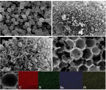
Figure 1. SEM images of SiO2 (a), HCH-N0.5 (b), PtSn/HCH-N0.5 (c) and EDS mapping (e) of
[image:5.596.119.478.417.723.2]
Fig. 1a shows SEM image of SiO2 spheres with the average size of around 400 nm in diameter,
which are basically uniform. The SEM images of HCH-N0.5 (Fig. 1b) and PtSn/HCH-N0.5 (Fig. 1c, d) indicated that the obtained HCH-N0.5 were opening composed of three dimensional hollow carbon hemispheres and there were microporous and mesopores in their walls. There are several advantages for this three-dimensional hollow carbon hemisphere: Firstly, hollow carbon hemisphere has highly graphitized carbon matrix to form a continuous dimensional conductive structure, this three-dimensional structure is conducive to a fast electron transport, which reduce the internal resistance of material. Secondly, the open three-dimensional channels are beneficial to the rapid diffusion of electrolyte ions into the material surface to participate reaction. Finally, the microporous and mesopores throughout the hollow hemisphere provide a high specific surface area of reaction and remarkably shorten diffusion distance of active substance. It can be seen from Fig. 1b and c that the HCH-N0.5 morphology is retained after the deposition of PtSn nanoparticles, and it is same for other HCH-Nx and HCH supports. Distribution of PtSn on the HCH-N0.5 was confirmed by SEM EDS-mapping analysis. As seen from the elemental EDS-mapping analysis (Fig. 1e), it was obviously that N, Pt and Sn were evenly distributed on HCH-N0.5 surface.
3.1.2. TEM and HRTEM analysis
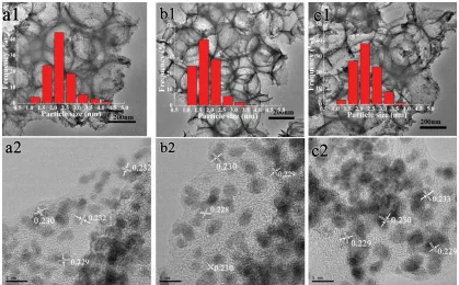
Figure 2. (a1, b1, c1) TEM images and particle size distribution histograms, (a2, b2, c2) high-resolution TEM image of PtSn/HCH-Nx (a for 0.2, b for 0.5, c for 1).
[image:6.596.89.508.379.639.2]
and the HRTEM images (Fig. 2a2, b2, c2) showed very similar morphology for three nitrogen-content PtSn/HCH-Nx catalysts. PtSn nanoparticles were homogenously dispersed on both inner and outer surface of the three HCH-Nx supports. The particle size histograms of PtSn nanoparticles for PtSn/HCH-N0.2, PtSn/HCH-N0.5 and PtSn/HCH-N1 are shown in the insets. As seen from the images, most of the PtSn nanoparticles exhibite a spherical shape without aggregation and have a narrow particle size distribution. The PtSn particle size for PtSn/HCH-N0.2 and PtSn/HCH-N1 is ranged from 1 to 4.5 nm, which is 2.3 and 2.5 nm, respectively. For the PtSn/HCH-N0.5, the mean particle size is 1.9 nm and the size distribution is in the range of 1-3.5 nm. Obviously, the PtSn/HCH-N0.5 catalyst had the narrowest size distribution and the smallest average particle size compared with PtSn/HCH-N0.2 and PtSn/HCH-N1, which was in good accordance with the XRD results. The high dispersion and small particle size significantly contribute to improve the activity of catalyst. The difference of PtSn nanoparticles size and distribution on HCH-Nx demonstrated that nitrogen content could adjust the microstructure of PtSn nanoparticles.
According to the HRTEM, the calculated interplanar spacing is 0.232, 0.229 and 0.231 nm for PtSn/HCH-N0.2, PtSn/HCH-N0.5 and PtSn/HCH-N1, respectively (Fig. 2a2, b2, c2), which are attributed to the expanded (111) plane of as-alloyed fcc Pt crystals, due to the introduction of Sn atoms [22, 23]. This result indicated that the PtSn NPs were highly crystallized. The effects of the nitrogen content on PtSn particle sizes of the PtSn/HCH-Nx can be estimated.
3.1.3. XPS analysis
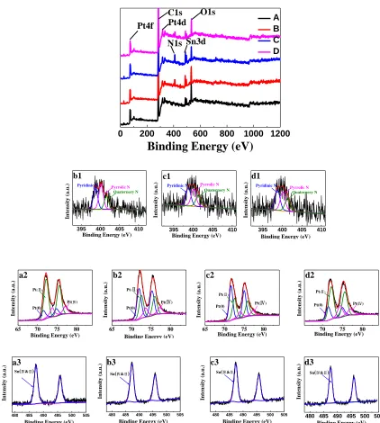
[image:7.596.84.511.579.666.2]As can be see from Fig. 3, XPS tests are performed to analyze the surface compositions and chemical states of PtSn/HCH and PtSn/HCH-Nx catalysts. For all the PtSn/HCH-Nx and PtSn/HCH, five predominant peaks were observed at binding energies of 72, 283, 408, 490 and 530 eV in wide scan, which were associated with the Pt4f, C1s, N1s, Sn3d and O1s signals, respectively [1]. This results indicated that the presence of Pt, C, N, Sn and O, which was in good agreement with the results of EDX elemental mapping.
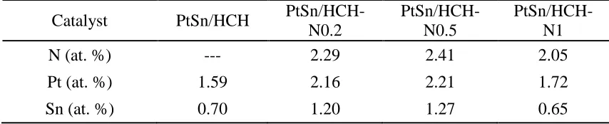
Table 1. XPS analysis: N, Pt, Sn atmomic concentrations of PtSn/HCH and PtSn/HCH-Nx.
Catalyst PtSn/HCH
PtSn/HCH-N0.2
PtSn/HCH-N0.5
PtSn/HCH-N1
N (at. %) --- 2.29 2.41 2.05
Pt (at. %) 1.59 2.16 2.21 1.72
0 200 400 600 800 1000 1200
Binding Energy (eV)
A B C D Pt4f C1s Pt4d N1s Sn3d O1s
Figure 3. Wide scan and fine XPS spectra of N1s, Pt4f and Sn3d for PtSn/HCH-Nx (A and a for N0, B and b for N0.2, C and c for N0.5, D and d for N1).
Table 1 shows the relative content of various elementals of all the PtSn/HCH-Nx and PtSn/HCH catalysts. For PtSn/HCH, there was no nirtrogen, and the loading amount of Pt and Sn was quite small. For other three PtSn/HCH-Nx catalysts, the nirtrogen content was increased with the increase of urea at first, whereas, it was decreased by further increasing the urea content. The amount of Pt and Sn reflected the similar tendency. This might be due to the position of doping N element can be used as the active site for anchoring metal nanoparticles, and it could increase the chemical binding energy between the support and catalyst particles, so the durability could be enhanced [15, 24]. The active sites was increased with the increase of the N element content, so there were more metal particles supported on HCH-N0.5 materials. Whereas, the excessive urea may damage the structure of
480 485 490 495 500 505
Sn(Ⅳ&Ⅱ)
In te n si ty ( a .u .)
Binding Energy (eV)
c3
480 485 490 495 500 505
Sn(Ⅳ&Ⅱ)
In te n si ty ( a .u .)
Binding Energy (eV)
b3
480 485 490 495 500 505
Sn(Ⅳ&Ⅱ)
In te n si ty ( a .u .)
Binding Energy (eV)
d3
480 485 490 495 500 505
Binding Energy (eV)
In te n si ty ( a .u .) a3
Sn(Ⅳ&Ⅱ)
395 400 405 410
d1 In te n si ty ( a .u .)
Binding Energy (eV)
Pyridinic N
Quaternery N Pyrrolic N
395 400 405 410
c1 In te n si ty ( a .u .)
Binding Energy (eV)
Pyridinic N
Quaternery N Pyrrolic N
395 400 405 410
In te n si ty ( a .u .)
Binding Energy (eV)
b1
Pyridinic N
Quaternery N Pyrrolic N
65 70 75 80
In te n si ty ( a .u .) Pt(0)
Pt(Ⅳ) Pt(Ⅱ)
Binding Energy (eV)
b2
70 75 80
In te n si ty ( a .u .)
Pt(0) Pt(Ⅳ) Pt(Ⅱ)
Binding Energy (eV)
d2
65 70 75 80
In te n si ty ( a .u .) Pt(0)
Binding Energy (eV) Pt(Ⅳ) Pt(Ⅱ)
c2
65 70 75 80
In te n si ty ( a .u .)
Binding Energy (eV) Pt(0)
Pt(Ⅳ) Pt(Ⅱ)
[image:8.596.81.503.83.553.2]
HCH to some extent, so the amount of loaded nitrogen decreased sharply, which leaded to the loaded Pt and Sn nanoparticles reduced. The amount of Pt and Sn was the highest for PtSn/HCH-N-0.5 which exhibited the highest activity and stability.
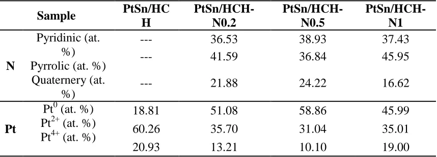
Table 2. XPS analysis: elemental N and Pt atomic concentrations of PtSn/HCH and PtSn/HCH-Nx.
Sample PtSn/HC H
PtSn/HCH-N0.2
PtSn/HCH-N0.5
PtSn/HCH-N1
N
Pyridinic (at. %) Pyrrolic (at. %) Quaternery (at.
%)
--- 36.53 38.93 37.43
--- 41.59 36.84 45.95
--- 21.88 24.22 16.62
Pt
Pt0 (at. %) Pt2+ (at. %) Pt4+ (at. %)
18.81 51.08 58.86 45.99
60.26 35.70 31.04 35.01
20.93 13.21 10.10 19.00
[image:9.596.85.514.166.320.2]
The proportions of N and Pt in different chemical states indicates that the greatest amount of nitrogen can be obtained by adding the moderate urea, that favors to form the optimal amount of pyridinic-N and graphitic N. More pyridinic N and graphitic N should be helpful to the formation of Pt (0) species and that is beneficial to the ethanol oxidation. This result is in good accordance with the value of electrocatalytic activity of the catalysts.
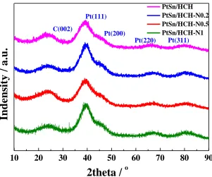
3.1.4. XRD analysis
10 20 30 40 50 60 70 80 90
C(002)
Pt(311) Pt(220)
Pt(200)
In
d
e
n
sit
y
/
a
.u
.
2theta /
o [image:10.596.148.449.240.491.2]PtSn/HCH PtSn/HCH-N0.2 PtSn/HCH-N0.5 PtSn/HCH-N1 Pt(111)
Figure 4. XRD pattern of PtSn/C and PtSn/HCH-Nx catalysts.
The XRD patterns of all the PtSn/HCH and PtSn/HCH-Nx catalysts are shown in Fig. 4. It was found that XRD patterns of the PtSn/HCH and PtSn/HCH-Nx catalysts were quite similar. The broad diffraction peaks at around 24.5o were observed in all diffractograms [29, 30], which were corresponded to the graphite (002) plane. The peaks appeared at 2θ around 39.6o, 45.8o, 66.7o and 80.8o corresponded to the typical diffraction peaks of a crystalline Pt(fcc) phase including Pt (111), Pt (200), Pt (220), and Pt (311) planes, respectively [29, 30]. It matched with the fcc Pt3Sn standard (PDF=35-1360) well and a small angle shift in contrast to the Pt standard peaks (PDF=04-0802), indicating the formation of Pt3Sn alloy [31]. This shift further implied that Sn atoms were incorporated into Pt cubic lattice, resulting the lattice parameter of the crystal of Pt (fcc) increased [3, 32]. The diffraction peaks of SnO2 should sppear about 34o and 52o in PtSn catalysts prepared by successive
reduction methods [31], but the peaks could not be observed at low SnO2 composition [33].
) cos(
D (1)
Where κ is s Scherrer’s constant, λ = 0.154 nm (X-ray radiation wavelength), β is the FWHM of the peak, and θ is the Bragg’s diffraction angle. The full width at half-maximum (FWHM) of the peak corresponding to Pt (220) was selected to reduce the interference of carbon overlapping peaks [35]. The calculated average crystal sizes were 2.6, 2.2, 1.9 and 2.3 nm for PtSn/HCH, PtSn/HCH-N0.2, PtSn/HCH-N0.5 and PtSn/HCH-N1 from the XRD, which illustrated that the particle size was related with the nitrogen content. The nanoparticle size of metal was biggest whilst the content of nitrogen was biggest under the same fabricating conditions.
3.2. Electrochemical measurements of as-prepared catalysts 3.2.1. Voltammetric characterization under inert gas
-0.2 0.0 0.2 0.4 0.6 0.8 1.0
-100 -50 0 50 100
C
u
r
r
e
t
d
e
n
si
ty
(
mA
·
mg
-1 Pt
)
Potential vs SCE
PtSn/C PtSn/HCH
PtSn/HCH-N0.2
PtSn/HCH-N0.5
PtSn/HCH--N1
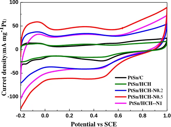
Figure 5. Cyclic voltammograms of the PtSn/C and PtSn/HCH-Nx catalysts in N2-saturated 0.5 M
H2SO4 electrolyte at a scan rate of 50 mV·s-1 at room temperature.
To verify the influence of the nirtrogen content of the HCH towards the ethanol electro-oxidation reaction, CV was used to evaluate the catalytic activity of as-prepared catalysts. Fig. 5 displays the voltammograms (CVs) of the PtSn/HCH, PtSn/HCH-Nx and PtSn/C in N2-saturated 0.5 M
H2SO4 electrolyte. All the CV curves of PtSn/HCH, PtSn/HCH-Nx and PtSn/C showed similar
features, it was observed that the peaks of chemisorbed hydrogen was ranged from -0.2 to 0.1 V, the region of double-layer capacitance region was ranged from 0.1 to 0.5 V and the region of surface oxide (OHads) formation/stripping region was ranged from 0.5 to 1 V [36]. The hydrogen peaks in H2SO4
[image:11.596.148.435.331.545.2]
oxophilic transition metals as Sn, Mo, Os and Ru. Electrochemical surface area (ESCA) of the Pt-based catalysts could be calculated using the following equation (2) [38]:
Pt ref
ads
L Q
Q ESCA
(2)
Where Qads is the hydrogen adsorption charge, commonly equivalent to hydrogen desorption
(mC·cm-2
), Qref is the hydrogen desorption charge of the Pt single crystallite (0.21 mC·cm-2) and LPtis
the Pt loading (g m-2).
The ECSA values of the PtSn/C, PtSn/HCH, N0.2, N0.5 and PtSn/HCH-N1 samples were 14.24, 13.27, 16.73, 35.25, and 12.63 m2·gPt-1, respectively. The values demonstrated
that the nirtrogen content had a significant effect on the ECSA of the catalysts. The ESCA value increased with the urea content increasing, then the ESCA decreased with further adding of urea, and the ESCA of PtSn/HCH-N0.5 was highest in our study. As a result, the PtSn/HCH-N0.5 displayed higher catalytic activity than the others catalysts, and the similar trends could be also observed in cyclic voltammograms for EOR (Fig. 6) and chronoamperometric curves (Fig. 7).
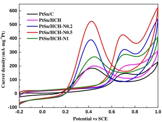
3.2.2. Ethanol electro-oxidation measurements
-0.2 0.0 0.2 0.4 0.6 0.8 1.0
-100 0 100 200 300 400 500 600
C
u
r
r
e
t d
e
n
si
ty
(
mA
·
mg
-1 Pt
)
Potential vs SCE PtSn/C
PtSn/HCH PtSn/HCH-N0.2 PtSn/HCH-N0.5 PtSn/HCH-N1
Figure 6. Cyclic voltammograms of PtSn/C, PtSn/HCH and PtSn/HCH-Nx in N2-saturated 0.5 M
H2SO4 solution containing 1 M ethanol at scan rate of 50 mV·s-1 at room temperature.
Fig. 6 shows CV curves of the PtSn/C, PtSn/HCH and PtSn/HCH-Nx catalysts for the EOR in 0.5 M H2SO4 solution containing 1 M ethanol at room temperature. All of the five curves displayed
[image:12.596.124.458.391.642.2]
typical ethanol oxidation current peak was observed near 0.71 V in the forward scan, whereas the peaks at about 0.42 V in the reverse scan was mainly due to the removal of intermediate species which were not completely oxidized [39]. The activity of the catalysts for EOR was normally determined by the value of the peak current in the positive scan [33]. It can be observed that the three PtSn/HCH-Nx catalysts containing nirtrogen showed superior catalytic activity compared to the other two PtSn catalysts without nirtrogen. Clearly, the maximum current density of all those catalysts was ranked as follows: PtSn/HCH-N0.5﹥PtSn/HCH-N0.2﹥PtSn/HCH-N1﹥PtSn/HCH﹥PtSn/C, which implied that the PtSn/HCH-N0.5 catalyst had the highest catalytic activity for ethanol electro-oxidation. The highest activity of PtSn/HCH-N0.5 was the result of the small size and the narrow distribution of PtSn nanoparticles on support. Smaller particle size could offer higher surface area for reactants to access.
3.2.3. Chronoamperometry
0 500 1000 1500 2000 2500 3000 3500
0 50 100 150 200 250 300
C
u
r
r
e
t
d
e
n
si
ty
(
mA
·
mg
-1 Pt
)
Time(s)
PtSn/C PtSn/HCH PtSn/HCH-N0.2 PtSn/HCH-N0.5 PtSn/HCH-N1
Figure 7. Current–time curves of PtSn/HCH-Nx and PtSn/C in N2 saturated aqueous solution of 0.5 M
H2SO4 containing1 M C2H5OH at a fixed potential of 0.6 V.
In order to obtain stable currents, chronoamperometric curves of on the PtSn/HCH-Nx and PtSn/C were measured in 0.5 M H2SO4 electrolyte containing 1 M ethanol at a constant potential of 0.6
[image:13.596.145.433.318.544.2][image:14.596.40.557.160.501.2]
dispersion of metal nanoparticles, promote the PtSn catalytic activity and stability in ethanol oxidation, which was corresponded with the TEM results (Fig. 2).
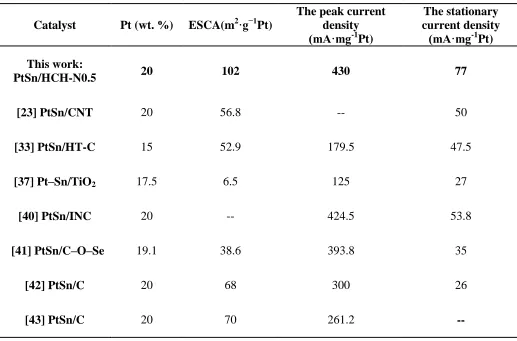
Table 3. Comparison of the activities for ethanol oxidation of PtSn/HCH-N0.5 and catalysts reported in literatures.
Catalyst Pt (wt. %) ESCA(m2·g−1Pt)
The peak current density (mA·mg-1
Pt)
The stationary current density
(mA·mg-1
Pt) This work:
PtSn/HCH-N0.5 20 102 430 77
[23] PtSn/CNT 20 56.8 -- 50
[33] PtSn/HT-C 15 52.9 179.5 47.5
[37] Pt–Sn/TiO2 17.5 6.5 125 27
[40] PtSn/INC 20 -- 424.5 53.8
[41] PtSn/C–O–Se 19.1 38.6 393.8 35
[42] PtSn/C 20 68 300 26
[43] PtSn/C 20 70 261.2 --
Moreover, the catalytic activity of PtSn/HCH-N0.5 was compared with other PtSn catalysts supported on different materials reported in literatures (Table 3). From the table 3, the PtSn/HCH-N0.5 has relatively larger value of ESCA, the peak current density and the stationary current density. This proves that PtSn/HCH-N0.5 has high catalytic activity and stability for ethanol oxidation.The excellent electrocatalytic activity of the PtSn/HCH-N0.5 can be attributed to its unique structure and the appropriate nitrogen content.
4. CONCLUSION
uniform spherical. The size and distribution of the PtSn nanoparticles could be controlled by doping nitrogen. In comparison with PtSn/C and PtSn/HCH, the PtSn/HCH-Nx (x=0.2, 0.5, 1) showed higher electrocatalytic activity because N species were introduced to the hollow carbon hemisphere. PtSn/HCH-N0.5 showed the best electrocatalytic performance for ethanol oxidation, which ascribed to the optimal proportion of N species. The value of ECSA, the current density and the stationary current density for PtSn/HCH-N0.5 are up to 35.25, 430and 77 mA·mgPt -1in 1 M ethanol solution, which are
about 2.5, 3 and 20 times for PtSn/C. The as-obtained current density for the PtSn/HCH-N0.5 electrode is higher than that of reported PtSn catalysts (Table 3). HCH-N0.5 supported greatest amount of pyridinic N and graphitic N, which not only intensed anchored of PtSn nanoparticles but also enhanced electric conductivity and stability while its structure was not damaged, the results indicated that PtSn/HCH-N0.5 was promising for DEFCs applications.
ACKNOWLEDGEMENTS
This research was supported by Tianjin Research Program of Application Foundation and Advanced Technology (15JCQNJC05700) and the State Key Laboratory of Inorganic Synthesis and Preparative Chemistry of Jilin University (No. 2017-31).
References
1. D.-H. Kwak, Y.-W. Lee, S.-B. Han, E.-T. Hwang, H.-C. Park, M.-C. Kim and K.-W. Park, J. Power Sources, 275 (2015) 557-562.
2. R. Rizo, D. Sebastián, M.J. Lázaro and E. Pastor, Appl. Catal. B-Environ., 200 (2017) 246-254. 3. A.O. Neto, R.R. Dias, M.M. Tusi, M. Linardi and E.V. Spinacé, J. Power Sources, 166 (2007)
87-91.
4. R.F.B. De Souza, L.S. Parreira, D.C. Rascio, J.C.M. Silva, E. Teixeira-Neto, M.L. Calegaro, E.V. Spinace, A.O. Neto and M.C. Santos, J. Power Sources, 195 (2010) 1589-1593.
5. J.M. Léger, S. Rousseau, C. Coutanceau, F. Hahn and C. Lamy, Electrochim. Acta, 50 (2005) 5118-5125.
6. S. García-Rodríguez, M.A. Peña, J.L.G. Fierro and S. Rojas, J. Power Sources, 195 (2010) 5564-5572.
7. L.Q. Hoa, M.d.C. Vestergaard, H. Yoshikawa, M. Saito and E. Tamiya, Electrochem. Commun., 13 (2011) 746-749.
8. W. Zhou, Appl. Catal. B-Environ., 46 (2003) 273-285.
9. C.-T. Hsieh and J.-Y. Lin, J. Power Sources, 188 (2009) 347-352.
10.D.-H. Lim, D.-H. Choi, W.-D. Lee and H.-I. Lee, Appl. Catal. B-Environ., 89 (2009) 484-493. 11.J. Asgardi, J.C. Calderón, F. Alcaide, A. Querejeta, L. Calvillo, M.J. Lázaro, G. García and E.
Pastor, Appl. Catal. B-Environ., 168-169 (2015) 33-41.
12.B.M. Thamer, M.H. El-Newehy, N.A.M. Barakat, M.A. Abdelkareem, S.S. Al-Deyab and H.Y. Kim, Electrochim. Acta 142 (2014) 228-239.
13.H. Huang, L. Ma, C.S. Tiwary, Q. Jiang, K. Yin, W. Zhou and P.M. Ajayan, Small, 13 (2017). 14.X. Peng, D. Chen, X. Yang, D. Wang, M. Li, C.C. Tseng, R. Panneerselvam, X. Wang, W. Hu, J.
Tian and Y. Zhao, ACS Appl. Mater. Interfaces, 8 (2016) 33673-33680.
15.Y. Wei, X. Zhang, Z. Luo, D. Tang, C. Chen, T. Zhang and Z. Xie, Nano-Micro Lett. 9 (2017). 16.M.-K. Seo, S. Yang, I.-J. Kim and S.-J. Park, Mater. Res. Bull. 45 (2010) 10-14.
17.Z. Yan, Z. Hu, C. Chen, H. Meng, P.K. Shen, H. Ji and Y. Meng, J. Power Sources, 195 (2010) 7146-7151.
19.T.C. Nagaiah, S. Kundu, M. Bron, M. Muhler and W. Schuhmann, Electrochem. Commun., 12 (2010) 338-341.
20.Y. Liu, Y. Zhang, C. Zhai, X. Li and L. Mao, Mater. Lett., 166 (2016) 16-18. 21.A. Chen, Y. Yu, T. Xing, R. Wang, Y. Li and Y. Li, Mater. Lett., 157 (2015) 30-33. 22.N. Chen, Y. Ren and E.W. Qian, J. Catal., 334 (2016) 79-88.
23.H. Song, M. Luo, X. Qiu and G. Cao, Electrochim. Acta, 213 (2016) 578-586. 24.G. Wu, R. Swaidan, D. Li and N. Li, Electrochim. Acta, 53 (2008) 7622-7629. 25.Y. Zhang, Y. Liu, W. Liu, X. Li and L. Mao, Appl. Surf. Sci., 407 (2017) 64-71.
26.Z. Bai, L. Niu, Q. Zhang, H. Feng, L. Yang, Z. Yang and Z. Chen, Int. J.Hydrogen Energy, 40 (2015) 14305-14313.
27.J. Yu, M. Jia, T. Dai, F. Qin and Y. Zhao, J. Solid State Electrochem. 21 (2016) 967-974. 28.M. Zhu, G. Sun and Q. Xin, Electrochim. Acta, 54 (2009) 1511-1518.
29.H. Li, G. Sun, L. Cao, L. Jiang and Q. Xin, Electrochim. Acta, 52 (2007) 6622-6629. 30.Z. Wen, Q. Wang, Q. Zhang and J. Li, Electrochem. Commun., 9 (2007) 1867-1872.
31.L. Jiang, L. Colmenares, Z. Jusys, G.Q. Sun and R.J. Behm, Electrochim. Acta, 53 (2007) 377-389. 32.W. Zhou, Solid State Ionics, 175 (2004) 797-803.
33.J. Thepkaew, S. Therdthianwong and A. Therdthianwong, J. Appl. Electrochem., 41 (2010) 435-444.
34.Y. Ma, H. Wang, S. Ji, V. Linkov and R. Wang, J. Power Sources, 247 (2014) 142-150. 35.R.G.C.S. dos Reis and F. Colmati, J. Solid State Electrochem., 20 (2016) 2559-2567. 36.L. Jiang, A. Hsu, D. Chu and R. Chen, Int. J. Hydrogen Energy, 35 (2010) 365-372.
37.A.E. Alvarez, A.N. Gravina, J.M. Sieben, P.V. Messina and M.M.E. Duarte, Mater. Sci. Eng., B. 211 (2016) 26-32.
38.D. González-Quijano, W.J. Pech-Rodríguez, J.I. Escalante-García, G. Vargas-Gutiérrez and F.J. Rodríguez-Varela, Int. J. Hydrogen Energy, 39 (2014) 16676-16685.
39.J.H. Kim, S.M. Choi, S.H. Nam, M.H. Seo, S.H. Choi and W.B. Kim, Appl. Catal. B., 82 (2008) 89-102.
40.H. Wang, Q. Zhao and Q. Ma, Ionics, 21 (2014) 1703-1709. 41.H. Wang, Q. Ma, J Solid State Electrochem, 19 (2015) 355–360.
42.B.J. Su, K.W. Wang, C.J. Tseng, C.H. Wang, Y.J. Hsueh, Int. J. Electrochem. Sci.,7 (2012) 5246 – 5255.
43.H. Wang, X.T. Zhang, R.F. Wang, S. Ji, W. Wang, Q.Z. Wang, Z.Q. Lei , J. Power Sources, 196 (2011) 8000–8003.