White Rose Research Online URL for this paper:
http://eprints.whiterose.ac.uk/142368/
Version: Accepted Version
Article:
Davidson, Zoe, Gonzalez-Izquierdo, Bruno, Higginson, Adam et al. (7 more authors)
(2019) An optically multiplexed single-shot time-resolved probe of laser–plasma dynamics.
Optics Express. pp. 4416-4423. ISSN 1094-4087
https://doi.org/10.1364/OE.27.004416
[email protected] https://eprints.whiterose.ac.uk/
Reuse
Items deposited in White Rose Research Online are protected by copyright, with all rights reserved unless indicated otherwise. They may be downloaded and/or printed for private study, or other acts as permitted by national copyright laws. The publisher or other rights holders may allow further reproduction and re-use of the full text version. This is indicated by the licence information on the White Rose Research Online record for the item.
Takedown
If you consider content in White Rose Research Online to be in breach of UK law, please notify us by
An optically multiplexed single–shot time
resolving probe of laser–plasma dynamics
Z.E. DAVIDSON
,
1B. GONZALEZ-IZQUIERDO,
1A. HIGGINSON
,
1K.L.
LANCASTER,
2S.D.R. W
ILLIAMSON, 1M. KING,
1D. FARLEY,
2D.
NEELY,
3,1P. MC
KENNA
1 ANDR.J. GRAY
1,*1Department of Physics, SUPA, University of Strathclyde, Glasgow, UK 2Department of Physics, University of York, York, UK
3Central Laser Facility, STFC Rutherford Appleton Laboratory, Didcot, Oxfordshire, UK
Abstract:
We introduce a new approach to temporally resolve ultrafast micron–scale processes via the use of a multi–channel optical probe. We demonstrate that this technique enables highly precise time resolved, two–dimensional spatial imaging of intense laser pulse propagation dynamics, plasma formation and laser beam filamentation within a single pulse over four distinct time frames. The design, development and optimization of the optical probe system is presented, as are representative experimental results from the first implementation of the multi–channel probe with a high power laser pulse interaction with helium gas jet target.
© 2019 Optical Society of America
1. Introduction
Laser-plasma interactions attract significant research interest in part because they offer a route to to accessing exotic states of matter, including fusion plasmas [1], and as a compact source of radiation [2]. It has been a central aim in these topics to experimentally measure the temporal and spatial evolution of the underpinning dynamics which drive the interaction.
The complex dynamics of these interactions evolve rapidly on timescales less than the laser pulse (femto– to pico–seconds) and are highly sensitive to initial plasma conditions and shot–to– shot variations in the laser pulse parameters [3]. There have been a number of recent results that highlight the sensitivity of the source properties to changes in the laser and plasma parameters within a narrow range [4–6]. Although some of these dynamics can be elucidated in numerical simulations, due to limitations in the physical processes that can be included in codes and the use of idealized input parameters, measurements in the laboratory give the most comprehensive insights. There presently exists a growing need for the development of experimental techniques which enable detailed and controlled investigation with high spatial and temporal resolution in order to investigate complex evolving laser–plasma dynamics such as self–focusing [7] or the propagation of higher-order modes (such as Laguerre-Gaussian beams) in plasma [8]. Progress in this area will open up a new dimension of experimental measurement and provide additional capability to quantify key factors which limit the control of laser–plasma driven radiation sources.
MUX DMUX Object Pulse generator Single laser pulse CCD Imaging system CCD CCD CCD Delay control
t = 0
t4 t3
t2 t1
t=temporal delay
2P
2S
1S
1P
2P
2S Delay
Delay
Delay
Delay
Polarisation rotation 1S
1P
50:50 1 and 2
Split 1, 2
Polarization rotation
[image:3.612.119.497.97.203.2]Polarization rotation
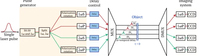
Fig. 1. Process flow diagram of multiplexed optical probe concept. A single ultrashort laser pulse is divided into four separate laser pulses which are uniquely encoded by frequency and polarization. The four pulses are independently delayed in time and then spatially multiplexed (MUX) to propagate co–linearly in order to optically probe a given point in space and time. The inverse process (DMUX) is then applied to spatially separate and form an image for each of the channels. This enable 2D spatial and picosecond temporal resolution over multiple frames with a single laser pulse.
due to shot–to–shot variations in the laser and plasma conditions [19–22], including changes in the laser spatial profile, energy and spectrum. This issue can be compounded by the fact that many large laser systems have low shot rates and low output stability, and therefore poor statistics with which to minimize the impact of shot–to–shot fluctuation on measurements [19]. This is a critical limitation highlighted as motivation for the development of alternative temporal measurement techniques such as time–sequence imaging by two–color probe [23] .
In this article, we present the design and the first measurements of a temporally resolved laser–plasma interaction tracking the propagation of a single laser pulse using a novel multi–
channel probe. We demonstrate that this optical probe system enables picosecond–scale
temporal resolution and two–dimensional spatial resolution of a single interaction. With these measurements we demonstrate that small variations in initial conditions strongly influence the subsequent interaction properties which consequently inhibits the reliability of optical probe measurements when obtained across repeated shots. This paper details the concept, design of the optical system and the first tests of the system on a high power laser–plasma experiment. Additionally, we envisage the multi–channel probe concept to potentially enhance existing approaches to temporally resolve ultra–fast phenomena across other fields of scientific research that are also inherently susceptible to stochastic phenomena [19], such as in pump–probe microscopy [24] and irreversible reaction dynamics [25].
2. System design
Probe beam 1054 nm, 480 mJ, 1 ps
BBO frequency doubling crystal
½ Wave-plate
Al mirror
Andor Neo CCD Cameras
Target
External set up
DBS PBS Al mirror BS Pellicle BS
DBS PBS PBS
Focusing lenses
Wollaston prism
Polarizer
1 S 1 P
2 P 2 S
MUX DMUX Imaging system
Pump beam 1054 nm, 150 J, 20 ps
Delay control Object
[image:4.612.120.493.110.276.2]Pulse generator
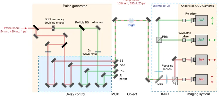
Fig. 2. Schematic of the experimental set up within the vacuum chamber where a high power pump laser pulse is focused into a gas target and a low–intensity probe pulse is passed through the internal multi–channel system and the demultiplex arrangement external to the chamber. The diagram details the optical system used in the multi–channel probe to generate the four uniquely encoded laser pulses, delay them in time, spatially multiplex and then demultiplex after the interaction point (object) to image the individual channels.
consisting of focusing lenses and CCD cameras.
A detailed technical schematic of the development from concept to the optical system design for use on a high power laser experiment is shown in Fig. 2. By splitting the initial P-polarized
pulse in two, one output can be frequency doubled by passing it through aβ–Barium Borate
(BBO) crystal of 50% conversion efficiency. This generates 1ω(1054 nm) and 2ω(527 nm)
channels which can both be divided again by a beamsplitter (BS), after which one of each
harmonic is passed through a half wave–plate to give a 90◦ polarization rotation, to produce
1ωS and 2ωS. The final result is four laser pulses (henceforth referred to as 1ωS, 1ωP, 2ωS and
2ωP) with uniquely distinguishable combinations of wavelength and polarization. To enable
independent timing control of each of the laser pulses a time delay slide is included along each beam path. The individual delay stages facilitate both fine and coarse control of the intervals between imaging, providing flexibility to observe developments at arbritrary timesteps over a few picoseconds and at later stages of the remnants of the interaction with larger steps of hundreds of picoseconds. After the timing stages, the four encoded pulses are made co–linear
using amultiplexerarrangement. The 1ωS and 1ωP pulses are spatially overlapped using a
polarizing beamsplitter (PBS). These two pulses are then spatially overlapped with the 2ωS pulse
via a 1ω/2ωdichroic beamsplitter (DBS). The final optic in the system for recombining is a
non-polarizing beam splitter (BS) which enables the 2ωP pulse to overlap with the other pulses.
The co–linear, temporally separated pulses are directed transversely, across the interaction of an intense laser pulse with a plasma, as an optical probe. The transmitted probe light is then directed
to thedemultiplexer, external to the vacuum chamber, where the co–linear probe pulses are split
to give a direct time resolved measurement of the evolving plasma electron density [29].
3. Experimental set up for use on high intensity laser–plasma interactions
The new optical probing technique was first tested in an intense laser–plasma interaction experiment. The multi–channel optical probe enables direct measurement of the propagation of a relativistically intense laser pulse in a high density sub–critical [30] plasma medium during a single interaction. The experiment was performed at the Rutherford Appleton Laboratory, Oxfordshire, UK, using the Vulcan Nd:Glass laser system in a dual short pulse beam configuration.
The probe beam was picked off from a larger 20 cm diameter beam with a total energy of≈30 J
and a pulse duration of≈1 ps. The probe beam was 2.54 cm in diameter with 480 mJ total energy.
The intense laser plasma interaction was driven by a 1054 nm laser with 150 J pulse energy
and 20 ps duration at full width at half maximum (FWHM). The laser was focused to≈5.6µm
(FWHM) using an F/3 off–axis parabola, reaching a peak intensity of≈1×10¹⁸W/cm2. The
laser was focused to the centre of a helium gas jet target, which was operated at pressures of up
to 100 bar, reaching electron densities of up to 1×1020cm−3(0.1nc[30]).
The optical probe was timed relative to this high intensity laser pulse using a streak camera. Although the streak camera could reach sub–2 ps temporal resolutions, the timing resolution
between the optical probe and the high intensity pulse was found to be≈ ±10 ps. This was due to
jitter in the electrical signal used to trigger the streak camera. The time delay for each pulse was adjusted using a time delay slide which had 2 ns (60 cm) maximum range of motion in a double
pass configuration. A magnescale encoder was used with a position accuracy of≈30 fs (≈10
µm). Initially all four optical probe pulses were overlapped in time with the high intensity pulse
and then moved in time to provide measurements at defined points in the interaction. As shown in Fig. 2, a combination of transmissive and reflective optics were used, after the time delay system, to achieve spatial overlap between the four pulses. This process resulted in significant energy losses in some of the channels. The transmission through the multiplexer was calculated
to be 0.125Et(1ωS), 0.25Et (1ωP), 0.06Et(2ωS), and 0.06Et (2ωP), whereEt is total input
laser energy.
After the optical probe passed through the plasma and the individual pulses spatially separated
in thedemultiplexersystem, the remaining sections of the optical probe were set up to act as a
Normarski–type interferometer for each of the pulses. Although interferometry was tested and demonstrated to work during the experiment, the reduction in signal caused by the introduction of a polarizer and Wollaston prism was found to reduce the signal–to–noise to an unacceptable level during high power laser shots due to the production of self–emission [31]. The data presented in the following sections is therefore limited to shadowgraphy measurements only. The field of
view of the optical probe imaging system was≈0.6 mm×0.5 mm with a resolution of≈7µm at
1ωand≈3.5µm at 2ω, in both dimensions, and magnification of≈29, for each of the channels.
4. Initial experimental results
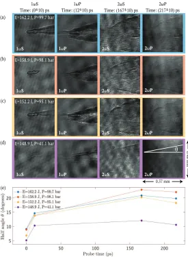
Fig. 3(a)–3(d) shows example measurements of the interaction of the intense laser pulse with a
helium gas target at a gas pressure ofP=99.7, 98.1, 95.1 and 41.1 bar respectively. From left to
right in Fig. 3, each of the separate output channels of the probe are shown for fixed timings relative
to the peak of the laser oft=0, 12, 167 and 217 ps, respectively. In these images the temporal
E=162.2 J, P=99.7 bar
1ωS 1ωP 2ωS 2ωP
0.48 mm
0.57 mm
1ωS Time: (0±10) ps
1ωP Time: (12±10) ps
2ωP Time: (217±10) ps 2ωS
Time: (167±10) ps
(b) E=158.9 J, P=98.1 bar
1ωS 1ωP 2ωS 2ωP
(c) E=152.2 J, P=95.1 bar
1ωS 1ωP 2ωS 2ωP
(d)
(e)
E=148.9 J, P=41.1 bar
1ωS 1ωP 2ωS 2ωP
(a)
[image:6.612.166.441.94.469.2]θ
Fig. 3. Shadowgraphy measurements of each probe output channel from the experiment for (a) E = 162.2 J, P = 99.7 bar (b) E = 158.9 J, P = 98.1 bar (c) E = 152.2 J, P = 95.1 bar, and (d) E = 148.9 J, P = 41.1 bar. (e) Averaged half–angle (θ) divergence of the plasma channel wall evolving at 0, 12, 167 and 217 ps measured directly from the sets of images(a)–(d).
the beam [7]. The peak laser intensity in this experiment is only slightly above the 1.24×10¹⁸
W/cm2relativistic threshold for the 1.054µm wavelength used here. In this regard, the plasma
electron Lorentz factor is close to unity and so we expect ponderomotive self–focusing effects to dominate at early times. However, given sufficient ponderomotive self-focusing, relativistic effects could play a role near the peak of the pulse [7].
The most salient point to be taken from these measurements is the observed variability in the channel evolution, despite only small fluctuations in the laser and gas target parameters. Across
the three examples of repeated laser shots Fig. 3(a)–3(c) the average gas pressure is 98 bar±2
bar (±2%) and the average laser energy is 158 J±5 J (±3 %). In this range we observe the early
3(c) both of these parameters are lower than in 3(b) where the early onset of the channel is not
observed in the 1ωS measurements. This earlier onset of the channel formation will induce
self–focusing, and at these densities beam collapse [33]. In the 1ωP measurements, a larger
degree of filamentation is clearly observed for Fig. 3(a) and 3(c) where the channel formation occurred earliest. This early time channel evolution induced by small random variations in the laser - such as an additional prepulse - or plasma parameters is a quintessential example of the utility that the multi–channel optical probe can provide. In a standard single channel optical probe arrangement the temporal dynamics are extracted over consecutive repeated laser shots, where it is impossible to differentiate the evolution of the plasma dynamics from random fluctuations in the initial conditions. Such an insight into the evolving stability of channel formation would be of particular interest for the fast ignitor concept in inertial confinement fusion [36].
The measurements for the later channels show a stagnation of the channel evolution for
t ≥150 ps, long after the laser pulse has passed. The 2ωS and 2ωP channels both suffer poor
signal–to–noise ratio due to pick up of the plasma self–emission. The stagnation in the evolution of the channel is clearly observed in Fig. 3(e) where at early time the channel half angle is shown to grow rapidly then saturate on time scales longer than the laser pulse duration. The
half angleθis calculated as defined in Fig. 3(d), overlaid on the the 2ωP channel. The initial
half–angle of the channel shown in Fig. 3(a)–3(c) is approximately 10◦, which is expected for
the F/3 focusing geometry used in this experiment and suggests that limited ponderomotive
self–focusing has occurred early in the interaction. Later in the interaction fort ≥12 ps the
angle of the channel has increased up to near 15◦which is approaching an F/2 focusing geometry,
induced by self–focusing of the laser pulse. The measurements at late time show an even steeper profile which is approaching an F/1 focusing geometry, which has then saturated by the final time step. In addition to the images shown in Fig. 3(a)–3(c), this measurement is also made, for comparison, for P = 41.1 bar and E = 148.9 J in Fig. 3(d) and the evolution is quite different. At early times breakdown of the background is observed but the full channel has not yet formed.
Fort≥12 ps a channel is present with a half–angle which approaches the initial F/3 geometry
and remains approximately constant for the succeeding time steps.
These measurements provide insight into the evolving picosecond–scale dynamics of laser– pulse propagation in underdense plasma and their sensitivity to fluctuations in initial plasma conditions and laser input parameters. This data highlights the importance of reproducible conditions to ensure reliability, especially when measurements are reconstructed from a series of consecutive shots.
5. Summary and outlook
splitter which is responsible for significant energy losses. The development of this system supports the growing capacity in the field to make controlled and precise time–resolved measurements of intense laser–plasma interactions. This will enable new insight into the underpinning physics which drive, for example, laser–driven radiation sources and which previously could not be measured experimentally during a single interaction. The novel concept presented here also has the potential to be extended and adapted for cross–disciplinary research interests which could benefit from temporally resolving ultrafast processes and particularly in cases where the underlying dynamics appear stochastic.
Funding
Engineering and Physical Sciences Research Council (EPSRC) (EP/R006202/1, EP/M018091/1,
EP/J003832/1).
Acknowledgments
The authors acknowledge the expertise of the Central Laser Facility staff.
Disclosures
The authors declare that there are no conflicts of interest related to this article.
References
1. M. Tabak, J. Hammer, M.E. Glinsky, W.L. Kruer, S.C. Wilks, J. Woodworth, E.M. Campbell, and M.D. Perry, “Ignition and high gain with ultrapowerful lasers,” Phys. Plasmas,1, 1626–1634 (1994).
2. S. Cipiccia, M.R. Islam, B. Ersfeld, R.P. Shanks, E. Brunetti, G. Vieux, X. Yang, R.C. Issac, S.M. Wiggins, G.H. Welsh, M. Anania, D. Maneuski, R. Montgomery, G. Smith, M. Hoek, D.J. Hamilton, N.R.C. Lemos, D. Symes, P.P. Rajeev, V.O. Shea, J.M. Dias, and D.A. Jaroszynski, “Gamma–rays from harmonically resonant betatron oscillations in a plasma wake,” Nat. Phys.7, 867–871 (2011).
3. A.J. Gonsalves, K. Nakamure, C. Lin, D. Panasenko, S. Shiraishi, T. Sokollik, C. Benedetti, C.B. Schroeder, C.G.R. Geddes, J. Van Tilborg, J. Osterhoff, E. Esarey, C. Toth, and W.P. Leemans, “Tunable laser plasma accelerator based on longitudinal density tailoring,” Nat. Phys.7, 862–866 (2011).
4. A. Higginson, R.J. Gray, M. King, S.D.R. Williamson, N.H.M. Butler, R. Wilson, R. Capdessus, C. Armstrong, J.S. Green, S.J. Hawkes, P. Martin, W.Q. Wei, S.R. Mirfayzi, X.H. Yuan, S. Kar, M. Borghesi, R.J. Clarke, D. Neely, and P. McKenna, “Near–100 MeV protons via a laser–driven transparency–enhanced hybrid acceleration scheme,” Nat. Commun.9, 724 (2018).
5. B. Gonzalez–Izquierdo, R.J. Gray, M. King, R.J. Dance, R. Wilson, J. McCreadie, N.M.H. Butler, R. Capdessus, S. Hawkes, J.S. Green, M. Borghesi, D. Neely, and P. McKenna, “Optically controlled dense current structures driven by relativistic plasma aperture–induced diffraction,” Nat. Phys.12, 505–512 (2016).
6. R.J. Gray, D.C. Carroll, X.H. Yuan, C.M. Brenner, M. Burza, M. Coury, K.L. Lancaster, X.X. Lin, Y.T. Li, D. Neely, M.N. Quinn, O. Tresca, C–G. Wahlström, and P. McKenna, “Laser pulse propagation and enhanced energy coupling to fast electrons in dense plasma gradients,” New J. Phys.16, 113075 (2014).
7. M.R. Siegrist, “Self–focusing in a plasma due to ponderomotive forces and relativistic effects,” Opt. Commun.16,
402–407 (1976).
8. J. Vieira, J.T. Mendonça, and F. Quéré, “Optical control of the topology of laser–plasma accelerators,” Phys. Rev. Lett.121, 054801 (2018).
9. M. Borghesi, A. Schiavi, D.H. Campbell, M.G. Haines, O. Willi, A.J. MacKinnon, L.A. Gizzi, M. Galimberti, R.J. Clarke, and H. Ruhl, “Proton imaging: a diagnostic for inertial confinement fusion/fast ignitor studies,” Plasma Phys. Control. Fusion43, 267–276 (2001).
10. L. Willingale, P.M. Nilson, A.G.R. Thomas, J. Cobble, R.S. Craxton, A. Maksimchuk, P.A. Norreys, T.C. Sangster, R.H.H. Scott, C. Stoeckl, C. Zulick, and K. Krushelnick, “High–power, kilojoule class laser channeling in millimeter– scale underdense plasma,” Phys. Rev. Lett.106, 105002 (2011).
11. D.J. Bradley, B. Liddy, and W.E. Sleat, “Direct linear measurement of ultrashort light pulses with a picosecond streak camera,” Opt. Commun.2, 391–395 (1971).
12. S. Jackel, B. Perry, and M. Lubin, “Dynamics of laser–produced plasmas through time–resolved observations of 2ω0
and3
2ω0harmonic light emissions,” Phys. Rev. Lett.37, 95–98 (1976).
14. A.J. Mackinnon, P.K. Patel, R.P. Town, M.J. Edwards, T. Phillips, S.C. Lerner, D.W. Price, D. Hicks, M.H. Key, S. Hatchett, S.C. Wilks, M. Borghesi, L. Romagnani, S. Kar, T. Toncian, G. Pretzier, O. Willi, M. Koenig, E. Martinolli, S. Lepape, A. Benuzzi-Mounaix, P. Audebert, J.C. Gauthier, J. King, R. Snavely, R.R. Freeman, and T. Boehlly, “Proton radiography as an electromagnetic field and density perturbation diagnostic,” Rev. Sci. Instrum.75, 3531–3536
(2004).
15. H. Shiraga, M. Nakasuji, M. Heya, and N. Miyanaga, “Two–dimensional sampling–image x–ray streak camera for ultrafast imaging of inertial confinement fusion plasma,” Rev. Sci. Instrum.70, 620–623 (1999).
16. J.S. Green, C.D. Murphy, N. Booth, R.J. Dance, R.J. Gray, D.A. MacLellan, P. McKenna, D. Rusby, and L. Wilson, “Single shot, temporally and spatially resolved measurements of fast electron dynamics using a chirped optical probe,” J. Instrum.9, P03003 (2014).
17. P. Antici, S.N. Chen, L. Gremillet, T. Grismayer, P. Mora, P. Audebert, and J. Fuchs, “Time and space resolved interferometry for laser–generated fast electron measurements,” Rev. Sci. Instrum.81, 113302 (2010).
18. Z. Najmudin, K. Krushelnick, M. Tatarakis, E.L. Clarke, C.N. Danson, V. Malka, D. Neely, M.I.K. Santala, and A.E. Dangor, “The effect of high intensity laser propagation instabilities on channel formation in underdense plasmas,” Phys. Plasmas10, 438–442 (2003).
19. J. Liang and L.V. Wang, “Single–shot ultrafast optical imaging,” Optica5, 1113–1127 (2018).
20. Z. Li, H. Tsai, X. Zhang, C. Pao, Y. Change, R.Zgadzaj, X. Wang, V. Khudik, G. Shvets, and M.C. Downer, “Single–shot visualization of evolving plasma wakefields,” AIP Conf. Proc.1117, 040010 (2016).
21. S.P.D. Mangles, A.G.R. Thomas, O. Lundh, F. Lindau, M.C. Kaluza, A. Persson, C.-G. Wahlström, K. Krushelnick, and Z. Najmudin, “On the stability of laser wakefield electron accelerators in the monoenergetic regime,” Phys. Plasmas14, 056702 (2007).
22. S.P.D. Mangles, C.D. Murphy, Z. Najmudin, A.G.R. Thomas, J.L. Collier, A.E. Dangor, E.J. Langley, W.B. Mori, P.A. Norreys, F.Z. Tsung, R. Viskup, B.R. Walton, and K. Krushelnick, “Monoenergetic beams of relativistic electrons from intense laser–plasma interactions,” Nature431, 535–538 (2004).
23. M.C. Kaluza, M.I.K. Santala, J. Schreiber, G.D. Tsakiris, and K.J. White, “Time–sequence imaging of relativistic laser–plasma interactions using a novel two–color probe,” Appl. Phys. B92, 475–479 (2008).
24. D. Grossmann, M. Reininghaus, C. Kalupka, M. Kumkar, and R. Poprawe, “Transverse pump–probe microscopy of moving breakdown, filamentation and self–organized absorption in alkali aluminosilicate glass using ultrashort pulse laser,” Opt. Express24, 23221 (2016).
25. P.R. Poulin and K.A. Nelson, “Irreversible organic crystalline chemistry monitored in real time,” Science313,
1756–1760 (2006).
26. K. Ward, “A short history of telecommunications transmission in the UK,” J. of The Commun. Net.5, 30–41 (2006).
27. M. Börner, J. Fils, A. Frank, A. Blažević, T. Hessling, A. Pelka, G. Schaumann, A. Schokel, D. Schumacher, M.M. Basko, J. Maruhn, An. Tauschwitz, and M. Roth, “Development of a Nomarski–type multi–frame interferometer as a time and space resolving diagnostic for the free electron density of laser–generated plasma,” Rev. Sci. Instrum.
83, 043501 (2012).
28. R. Benattar, C. Popovics, and R. Sigel, “Polarized light interferometer for laser fusion studies,” Rev. Sci. Instrum.50,
1583–1586 (1979).
29. L.B. Da Silva, T.W. Barbee, Jr., R. Cauble, P. Celliers, D. Ciarlo, S. Libby, R.A. London, D. Matthews, S. Mrowka, J.C. Moreno, D. Ress, J.E. Trebes, A.S. Wan, and F. Weber, “Electron density measurements of high density plasmas using soft x–ray laser interferometry,” Phys. Rev. Lett.74, 3991–3994 (1995).
30. T.J.M. Boyd and J.J. Sanderson,The Physics of Plasma(Cambridge University, 2003).
31. S.D. Baton, H.A. Baldis, T. Jalinau, and C. Labaune, “Fine–scale spatial and temporal structures of second harmonic emission from an underdense plasma,” Europhys. Lett.23, 191–196 (1993).
32. E. Esarey, C.B. Schroeder, B.A. Shadwick, J.S. Wurtele, and W.P. Leemans, “Nonlinear theory of nonparaxial laser pulse propagation in plasma channels,” Phys. Rev. Lett.84, 3081–3084 (2000).
33. R. Fedosejevs, X.F. Wang, and G.D. Tsakiris, “Onset of relativistic self–focusing in high density gas jet targets,” Phys. Rev. E.56, 4615–4639 (1997).
34. G.A. Askaryan, “Waveguide properties of a tubular light beam,” Zh. Eksp. Teor. Fiz.28, 732–733 (1969).
35. D. Umstadter, “Relativistic laser–plasma interactions,” J. Phys. D: Appl. Phys.36, 151–165 (2003).