UNIVERSITI TEKNIKAL MALAYSIA MELAKA
DESIGN OF AUTOMATIC WORKPIECE CLAMP FOR BRIDGEPORT
VERTICAL MILLING MACHINE
This report submitted in accordance with requirement of the Universiti Teknikal Malaysia Melaka (UTeM) for the Bachelor Degree of Manufacturing Engineering
(Robotics & Automation) (Hons.)
By
AHMAD ZAHIN BIN AHMAD AKMAR
B051310197
940315-14-5467
DECLARATION
I hereby, declared this report entitled “Design of Automatic Workpiece Clamp for Bridgeport Vertical Milling Machine” is the results of my own research except as cited in references.
Signature : ………
Author’s Name : AHMAD ZAHIN BIN AHMAD AKMAR
APPROVAL
This report is submitted to the Faculty of Manufacturing Engineering of Universiti Teknikal Malaysia Melaka as partial fulfillment of the requirements for the degree of Bachelor of
Manufacturing Engineering (Robotics & Automation) (Hons.). The members of the supervisory committee are as follows:
i
ABSTRACT
ii
ABSTRAK
iii
DEDICATION
To my beloved family, friends and lecturers whose have guided and inspired me to complete this project successfully. Also, to my late mother Rahmah Hassan who always want me to
iv
ACKNOWLEDGEMENT
Assalamualaikum w.b.t.
v
TABLE OF CONTENTS
Abstract i
Abstrak ii
Dedication iii
Acknowledgement iv
Table of Contents v
List of Tables ix
List of Figures xi
List of Abbreviations xiii
List of Symbols xiv
CHAPTER 1: INTRODUCTION
1.1 Background of The Project 1
1.2 Problem Statement 2
1.3 Objectives 3
1.4 Scopes 3
CHAPTER 2: LITERATURE REVIEW
2.1 Bridgeport Vertical Milling Machine 5
2.2 Workpiece Clamp of Bridgeport Vertical Milling Machine 7
vi
2.3.1 Conventional Power Screw Drive System 8
2.3.1.1 Square Thread 9
2.3.1.2 Acme Thread 10
2.3.1.3 Buttress Thread 10
2.3.2 Hydraulic Clamping Drive System 11
2.3.3 Pneumatic Clamping Drive System 12
2.3.4 Electric Power Clamping System 13
2.4 Comparison Between Hydraulic, Pneumatic and Electric Drive System 15
2.5 Locating and Clamping Principles 16
2.5.1 Principles for Selecting Supporting and Locating Surfaces 17 2.5.2 Principles of Selecting Clamping Surfaces 18 2.5.3 Principles for Selecting Supporting and Locating Positions 19 2.5.4 Principles for Selecting Clamping Positions 19
2.6 Factors in Selecting Clamps 20
2.7 Computer Aided Design (CAD) Software 21
2.7.1 SolidWork 22
2.7.2 CATIA 22
2.7.3 AutoCAD 23
2.7.4 Automation Studio Software 23
2.8 Computer Aided Manufacturing (CAM) Software 23
2.8.1 Finite Element Analysis (FEA) 24
2.8.2 Simulation Express Analysis Wizard Software 24
vii
2.9 Summary 25
CHAPTER 3: METHODOLOGY
3.1 Flow Chart 27
3.2 Gantt Chart 29
3.3 Design Ideas 29
3.4 Comparison Between Generated Design Ideas 31
3.5 Method in Conducting The Project 33
3.6 Drawings Using SolidWorks 34
3.7 Finite Element Analysis Using ANSYS Simulation Software 35
3.8 Summary 36
CHAPTER 4: DESIGN, RESULT AND ANALYSIS OF AUTOMATIC WORKPIECE
CLAMP
4.1 Automatic Workpiece Clamp Design 37
4.1.1 Base 38
4.1.2 Supporter 38
4.1.3 Pneumatic Cylinder 39
4.1.4 Mounting Bolt for Pneumatic Cylinder 40
4.1.5 Mounting Bolt for Supporter 40
4.1.6 Fitting 41
4.2 Full Assembly of Automatic Workpiece Clamp 42
viii
4.4 List of Standard Part 45
4.5 List of Fabricate Part 46
4.6 Analysis on Automatic Workpiece Clamping Design System 47 4.6.1 Analysis on The Force Exerted by The Cylinder 47
4.6.2 Analysis on The Automatic Workpiece Clamp 48
4.6.2.1 Applied 200 N on The Clamping Plate 49
4.6.2.2 Applied 1000 N on The Clamping Plate 54
4.6.2.3 Applied 200 N on The Supporter 58
4.6.2.4 Applied 1000 N on The Supporter 63
4.7 Sustainability In Design 67
4.8 Conclusion On The Analysis Of Automatic Workpiece Clamp 67
CHAPTER 5: CONCLUSION AND SUGGESTION FOR FUTURE WORK
5.1 Conclusion 68
5.2 Suggestion for Future Work 69
REFERENCES 70
APPENDICES
A Gantt Chart for FYP 1 73
B Gantt Chart for FYP 2 74
C Detail Drawing of Base 75
D Detail Drawing of Supporter 76
ix
LIST OF TABLES
2.1 Basic comparison between hydraulic, pneumatic and electric drive system 16 2.2 Characteristics in designing a supporting and locating surfaces 17
3.1 Step 1 of AHP 31
3.2 Pairwise comparison matrix for the clamping force 32
3.3 Pairwise comparison matrix for the simplicity 32
3.4 Pairwise comparison matrix for the cost 32
3.5 Pairwise comparison matrix for the maintenance 32
3.6 Pairwise comparison matrix with respect to the goal 32
4.1 List of parts for full assembly 44
4.2 List of standard parts 45
4.3 List of fabricate parts 46
4.4 Properties of Aluminium Alloy 49
x
4.9 Result for von Mises Stress when 1000 N force applied on clamping plate 54 4.10 Result for displacement when 1000 N force applied on clamping plate 55 4.11 Result for deformation when 1000 N force applied on clamping plate 56 4.12 Result for factor of safety when 1000 N force applied on clamping plate 57
4.13 Properties of Alloy Steel 58
xi
LIST OF FIGURES
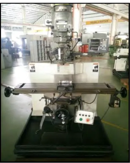
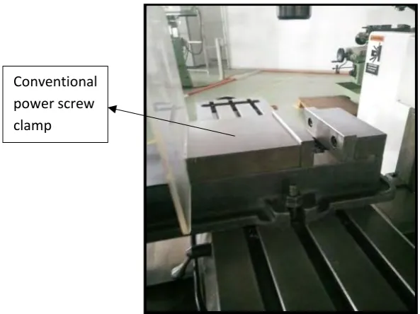
1.1 Bridgeport Vertical Milling Machine at machine shop at Block B of FKP 2 1.2 Conventional power screw workpiece clamp for Bridgeport 3
Vertical Milling Machine
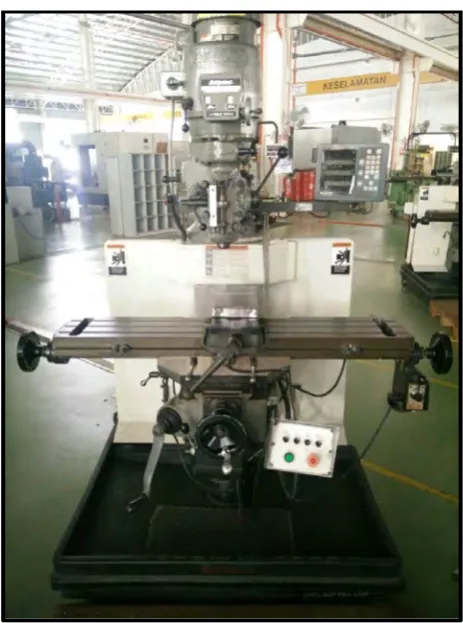
2.1 Bridgeport Vertical Milling Machine 6
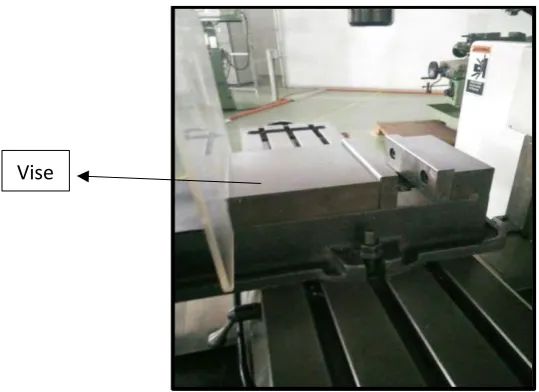
2.2 Vise of Bridgeport Vertical Milling Machine 7
2.3 Conventional power screw milling machine vise 9
2.4 Square thread power screw 9
2.5 Acme thread power screw 10
2.6 Butttress thread power screw 11
2.7 Example of hydraulic clamping drive system circuit 12 2.8 Example of pneumatic clamping drive system circuit 13 2.9 Energy transfer and transformation line for hydraulic and pneumatic system 13
2.10 Electrical screw clamping system 14
2.11 Energy transfer and transformation line for electrical system 14 2.12 A free body in space and its six degrees of freedom 17 2.13 Preferable positions of clamps on workpiece. (left) vertical clamping, 19
xii
2.14 Workpiece distortion due to incorrect placement of clamp 20
3.1 Flow chart of the project work 28
3.2 Design and assembly view for the design idea 1 30
3.3 Design and assembly view for the design idea 2 30
4.1 Isometric view of the base 38
4.2 Isometric view of the supporter 39
4.3 Isometric view of pneumatic cylinder 39
4.4 Isometric view of the mounting bolt for cylinder 40
4.5 Isometric view of the mounting bolt for supporter 41
4.6 Isometric view of fitting 41
4.7 Full assembly of the automatic workpiece clamp 42
4.8 Exploded view of the full assembly of the workpiece clamp 43
4.9 List of parts for full assembly 44
4.10 Model of clamping plate 50
xiii
LIST OF ABBREVIATIONS
AHP - Analytical Hierarchy Process
2D - Two Dimension
3D - Three Dimension
CAD - Computer Aided Design
CAE - Computer Aided Engineering
CAM - Computer Aided Manufacturing
CATIA - Computer Aided Three-dimensional Interactive Application
CNC - Computer Numerical Control
DOF - Degree of Freedom
FEA - Finite Element Analysis
FKP - Fakulti Kejuruteraan Pembuatan
FoS - Factor of Safety
xiv
LIST OF SYMBOLS
% - Percentage
° - Degree
cm - Centimeter
etc - Et Cetera
Kg - Kilo Gram
kW - Kilo Watt
mm - Milimeter
N - Newton
m - Meter
Pa - Pascals
1
CHAPTER 1
INTRODUCTION
1.1Background Of The Project
2
Figure 1.1: Bridgeport Vertical Milling Machine at Machine Shop at Block B of FKP
1.2Problem Statement
3
Figure 1.2: Conventional Power Screw workpiece clamp for Bridgeport Vertical Milling Machine
1.3Objective
i. To design an automatic workpiece clamp for Bridgeport Vertical Milling Machine. ii. To develop soft prototype of the above designed automatic workpiece clamp.
1.4Scope
i. To design an automatic workpiece clamp that is to be focused on a rectangular shape workpiece because it is the common shape of workpiece to be processed by milling machine. The maximum dimensions of workpiece to be clamped are as follows: Length: 15 cm
Width: 11 cm Thickness: 5 cm
ii. Workpiece material: Steel, Aluminium, etc.
4
5
CHAPTER 2
LITERATURE REVIEW
This chapter provides literature review in which the sources and information are obtained from the internet, journals, articles and other sources. This chapter will discuss and explain about the Bridgeport Vertical Milling Machine, clamping system of the Bridgeport Vertical Milling Machine, existing clamping system, locating and clamping principles and factors in selecting clamp to generate any design ideas. Several types of Computer Aided Design (CAD) and Computer Aided Manufacturing (CAM) software are to be reviewed for selection of the most suitable one for this project.
2.1 Bridgeport Vertical Milling Machine
6
Milling machines are an important industrial tool for machining solid materials like wood and metal. They can perform a vast number of functions ordinarily done by hand, thus speeding up and facilitating a faster and more efficient workflow. Bridgeport vertical milling machine is a conventional milling machine which need to be operated manually. This machine can do most of the operation like a CNC milling machine but the production time is much slower due to many factors like positioning and clamping the workpiece are done manually.
[image:23.595.189.421.323.635.2]Bridgeport Vertical Milling machine as shown in Figure 2.1 has 4kW power. Size of this machine is 3000 x 1970 x 2250 (mm) and the weight is 1450 Kg. The maximum spindle speed of this machine is 4200 rpm.
7
2.2 Workpiece Clamp of Bridgeport Vertical Milling Machine.
[image:24.595.128.398.356.552.2]A clamp is fastening device used to hold or secure objects tightly together to prevent movement or separation through the application of inward pressure. Once workpiece is located, it is necessary to press it against locating surfaces and hold it there against the force acting upon it. (V. Paramasivam et. al., 2010). This action is refer as clamping process and the mechanisms used for this action are known as workpiece clamps. A vise is used in Bridgeport Vertical Milling machine to clamp and hold the workpiece again the force acting upon it during milling operation. It is a type of conventional power screw clamp that need human energy to drive the screw to tighten the vise. (M. Amirul, 2014). Figure 2.2 shows the vise of Bridgeport Vertical Milling Machine.