ISDN
Integrated Services Digital Network (ISDN) was
developed by ITU-T in 1976. It is a set of protocols
that combines digital telephony and data transport
services.
The whole idea is to digitize the telephone network
to permit the transmission of audio, video, and text
over existing telephone lines.
ISDN is an effort to standardize subscriber services,
provide user/network interfaces, and facilitate the
internetworking capabilities of existing voice and
data networks.
The goal of ISDN is to form a wide area network that
provides universal end-to-end connectivity over
digital media. This can be done by integrating all of
the separate transmission services into one without
ISDN
The purpose of the ISDN is toprovide fully integrated digital
services to users. These services fall into three categories:
Bearer services Teleservices
Supplementary services
Bearer services provide the means to
transfer information (voice, data, and video) between users without the network manipulating the content of that information. Bearer services
belong to the first three layers of the OSI reference model and are well defined in the ISDN standard.
In teleservicing the network may
change or process the contents of the data. These services correspond to layers 4-7 of the OSI model.
Teleservices rely on the facilities of the bearer services and are designed to accommodate complex user needs without the user having to be aware of the details of the process.
Supplementary services are those
services that provide additional functionality to the bearer services and teleservices.
History
Initially, telecommunications
networks were entirely
analog networks and were used for the transmission of analog information in the
form of voice. The local loops connecting the subscriber’s handset to the telephone
company’s central office were also analog.
With the advent of DSP,
subscribers needed to exchange data as well as voice. Modems were
developed to allow digital exchanges over existing
History
To reduce cost and improve performance, the telephonecompanies gradually began to add digital technologies while continuing their analog services to their
customers.
Next, customers began to require access to a variety of networks, such as packet-switched networks and circuit-switched networks. To meet these needs, the telephone companies created Integrated Digital Networks (IDNs). An IDN is a combination of networks available for different
purposes. Access to these networks is by digital pipes, which are
time-multiplexed channels sharing very high speed paths. Customers can use their local loops to transmit both voice and data to their telephone company’s central office. The office then directs these calls to the appropriate digital networks via the digital pipes. Though the majority of subscribers today
continue to use analog local loops, digital local loop services such as switched/56, DDS and DS are
History
The ISDN integratescustomer services with the IDN. With ISDN all customer services will become digital rather than analog, and the flexibility offered by the new technology will allow
customer services to be
made available on demand. Most important, ISDN will
allow all communication connections in a home or building to occur via a single interface.
Each user is linked to the central office through a
digital pipe. These pipes can be of different capacities to allow different rates of
transmission and support different subscriber needs.
Subscriber access to the ISDN
To allow flexibility, digital pipes between customers and the ISDN office (the
subscriber loops) are organized into multiple channels of different sizes.
The ISDN standard defines three channel types:
Bearer (B) channels---64 kbps
Data (D) channels ---16, 64 kbps
Hybrid (H) channels ---384, 1536, 1920 kbps
Bearer channel is the basic user channel and can carry any type of digital
information in full-duplex mode as long as the required transmission rate does not exceed 64 kbps. Several transmissions can be accommodated at once if the signals are multiplexed first.
Multiplexed transmissions of this sort, however, must be destined for a single
recipient. A B channel carries transmissions end-to-end. It is not designed to
demultiplex a stream midway in order to separate and divert transmissions to more than one recipient.
A data channel (D channel) can be either 16 or 64 kbps, depending on the needs of
the user. Although the name says data, the primary function of a D channel is to carry control signaling for the B channels using a method called common-channel (out-of-band) signaling.
In this mechanism, a subscriber uses the D channel to connect to the network and
secure a B channel connection. The subscriber then uses the B channel to send actual data to another user. All the devices attached to a given subscriber loop use the same D channel for signaling, but each sends data over a B channel dedicated to a single exchange for the duration of the exchange.
Less common uses for the D channel include low-rate data transfer and applications
such as telemetry and alarm transmission.
H channels are available with data rates of 384 Kbps (H0), 1536 Kbps (H11), or
User Interfaces
Digital Subscriber loops are of twotypes: basic rate interface (BRI) and primary rate interface (PRI). Both include one D channel and some number of either B or H channels.
BRI specifies a digital pipe consisting of two B channels and one 16 kbps D
channel.
BRI is designed to meet the needs of residential and small-office customers using the existing local-loop cable. PRI specifies a digital pipe with 23 B
channels and one 64 Kbps D channel. PRI was designed to be compatible
with existing T-1 lines. In Europe, the PRI includes 30 B channels and 2D channels, giving it a capacity of 2.048 Mbps-the capacity of an E-1 line.
For more specialized transmission
needs, other channel combinations are also supported by the PRI standard. They are 3H0+D, 4H0+D & H12+D.
Functional Grouping
In the ISDN standard, the devicesthat enable users to access the services of the BRI or PRI are
described by their functional duties and collected in functional
groupings.
Functional groupings used at the
subscriber’s premises include
network terminations (types 1 and 2), terminal equipment (types 1 and 2) and terminal adapters.
NT1 device controls the physical
and electrical termination of the ISDN at the user’s premises and connects the user’s internal system to the digital subscriber loop.
An NT1 organizes the data streams
from a connected subscriber into frames that can be sent over the digital pipe, and translates the frames received from the network into a format usable by the
subscriber’s devices.
An NT1 synchronizes the timing of
Functional Grouping
A NT2 device performs functions at the physical, data
link and network layers of the OSI model.
NT2s provide multiplexing (layer 1), flow control ( layer
2), and packetizing (layer 3). It provides intermediate
signal processing between the data-generating devices
and an NT1. The NT1 is still required to provide a
physical interface to the network. NT2s are primarily
used to interface between a multi-user system and an
NT1 in a PRI.
The term TE is used by the ISDN standard to mean the
same thing as DTE in other protocols. It refers to digital
subscriber equipment. TE1 is any device that supports
the ISDN standards. Examples are digital telephones,
integrated voice/data terminals etc.
To provide backward compatibility with a customer’s
existing equipment, the ISDN standard defines a second
level of terminal equipment called terminal equipment 2.
TE2 devices are not immediately compatible with an
Reference Points
Reference point refers tothe label used to identify individual interfaces
between two elements of an ISDN installation.
R defines the connection
between a TE2 and a TA.
S defines the connection
between a TE1 or TA and an NT1 or NT2.
T defines the interface
between an NT2 and an NT1.
U defines the interface
between an NT1 and the ISDN office.
The ISDN Layers
In ISDN, B channels are foruser-to-user communication and D channels are
predominantly for user-to-network signaling. These two functions require different protocols from each other at many of the OSI layers.
Besides, a primary
consideration of the ISDN is global integration. Maintaining the flexibility required to keep the network truly integrated using public services requires a great deal of management.
For these reasons, the ITU-T
has devised an expanded model for the ISDN layers where it is defined in three separate planes: the user plane, the control plane, and the management plane.
All three planes are divided
into seven layers that
correspond to the OSI model.
The ISDN Layers
At the physical layer, the B and D channels are alike. They use either the BRI or PRI interfaces and devices discussed earlier. At the data link layer, the Bchannel uses LAPB or some version of it. At the network layer, the B channel has many options. B channels can connect to circuit-switched networks, packet-switched networks
(X.25), Frame relay networks, and ATM networks, among others.
The user-plane options for layers 4 through 7 are left to the user and are not defined specifically in the ISDN.
In summary, we will discuss the physical layer shared by the B and D channels and the second and third layers of the D channel standard.
Physical Layer
The ISDN physical layerspecifications are defined by two ITU-T standards: I.430 for BRI access and I.431 for PRI access. These standards define all aspects of the BRI and PRI. Of these aspects, four are of primary importance:
The mechanical and electrical
specifications of interfaces R, S, T, and U.
Encoding
Multiplexing channels to make
them carriable by the BRI and PRI digital pipes.
Power supply
A subscriber connects to the
BRI using the R, S, and U
interfaces (reference points).
Physical Layer Specifications for BRI
The R interface is not defined by
the ISDN. A subscriber can use any of the EIA standards (such as EIA-232, EIA-499, or EIA-530) or any of the V or X series standards
(such as X.21).
For the S interface, the ITU-T
specifies the ISO standard,
ISO8887. This standard calls for four-, six-, or eight-wire
connections. At least four wires are necessary to support full-duplex
communication over every B or D channel. The jacks and plugs for these connections, along with the electrical specifications for each
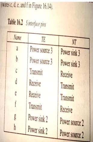
Physical Layer Specifications for BRI
[image:15.720.21.330.36.507.2] The individual wires in an S interface connection are organized according to table 16.2. Only four of the wires are necessary for balanced transmission of data in full-duplex mode.
The standard provides three methods for supplying power. In the first, the NT1 is the supplier. The power can come from a battery or power outlet, or it can come from the ISDN center to the NT1 (4 wires are used).
In the second case, the power again comes from the NT1, but two separate lines are used to relay it to the TE (6 wires are used).
ISO8887 allows for another possibility: that the TE supplies the power itself and passes it to other TEs. The ISDN, however, does not use this version. A two- or three-pair twisted cable is
adequate to support all of the ISDN defined uses. The signal used in the S interface is pseudoternary encoding.
Physical Layer Specifications for BRI
For the U interface (digital
subscriber or local loop), the ITU-T specifies a single-pair twisted-pair cable in each direction. Encoding for this interface uses a method called two binary, one
quaternary (2B1Q). 2B1Q uses four voltage levels instead of two. Each level can therefore represent two bits rather than one, thereby enabling more efficient use of the available bandwidth. The four voltage levels represent the dibits 00, 01, 10, and 11.
BRI Frame
Each B channel is sampledtwice during each frame
(eight bits per sample). The D channel is sampled four times during each frame (one bit per sample). The entire frame consists of 48 bits: 32 bits for the B
channels, 4 bits for the D channel, and 12 bits of overhead.
The reason that each B
channel is sampled twice and the D channel four times is to create a longer frame so that it makes the size of the BRI frame a
precise match for the data portion of an ATM cell.
Connection and Topology
BRI services can be supported by either a bus or star topology. The main restriction governing the choice of topology for a BRI is the distance of the data devices from the NT1. In a point-to-point connection, each device can be as far as 1000 meters away from the NT1. In a multipointconnection, however, the maximum length of the line generally cannot be more than 200 meters. This restriction is necessary to ensure frame
synchronization.
However, if we cluster the devices at the end of the link farthest from the NT1, we can extend the length of the link to 500 meters. Star topology links can be as long as 1000 meters.
As many as eight devices can be connected to an NT1. Of these, only two can access the B channels at one time, one exchange per channel.
Every device, however, can contend for access to the D channel. D
channels use a mechanism like CSMA to control access. Once a device has access to the D channel, it can
request a B channel. If a B channel is available, the connection is made by the D channel and the user may then
Physical Layer Specifications for PRI
Interfaces associated with PRI usage include R, S, T, and U. The R and S standards are the same as those
defined for the BRI. The T standard is identical to the S standard with the substitution of B8ZS encoding. The U interface is the same for both
standards except that the PRI rate is 1.544 Mbps which allows the PRI to be implemented using T-1
specifications.
Connection and topology
considerations for linking data
generating devices to an NT2 can be the same as those described for the device-to-NT1 links in the BRI, or they can differ. Specific
implementation depends on the
application. The link from the NT2 to the NT1, however, must always be
PRI Frame
The B and D channels are multiplexed usingsynchronous TDM to create a PRI frame. The frame format is identical to that defined for T-1 lines. Notice that the PRI frame samples each channel, including the D channel, only once per frame.
B and D channels use
different data link protocols. B channels use LAPB protocol. The D channel uses LAPD
which is basically HDLC with a few modifications: LAPD can be used in either
unacknowledged (without sequence numbering) or
acknowledged (with sequence numbering) formats. The
second difference is
LAPD Addressing
The SAPI field identifies thetype of upper-layer service using the frame. It indicates the intended use of the D channel. It is a 6 bit field and can therefore define up to 64 different service
access points. To date, however, only four of the possible bit combinations have been assigned:
000000 call control for NL
000001 call control for UL
010000 packet comm.
111111 management
TEI field is the unique
address of the TE. It
consists of seven bits and can therefore identify up to
Network Layer
The network layer functions ofthe D channel are defined by the ITU-T Q.931 standard. The network layer packet is called a message. A message is
encapsulated in the information field of an LAPD I-frame for
transport across a link.
The format of the message
consists of a small but variable number of fields. These fields are of four types:
Protocol discriminator
Call reference
Message type
Information elements
The protocol discriminator field
identifies the protocol in use.
For Q.931, the value of this field
Network Layer
The call reference is thesequence number of the call.
The message type is a
one-byte field that identifies the purpose of the message.
There are four categories of message types:
Call establishment messages
Call information messages
Call clearing messages
Miscellaneous messages
An information elements field
carries specific details about the connection that are
required for call
establishment, for example, the addresses of the sender and receiver, routing
information, and the type of network that is desired for the B channel exchange.
Addressing
An important type of information element is addressing. The country code consists of three digits. The NC field is the national code and consists of two digits. It identifies the specific network in countries with more than one ISDN network. The subscriber number is the 10-digit number familiar from national telephone numbers: a three-digit area code and a seven-digit phone number. Together these 15 digits define the access to a
subscriber NT1.
Often, however, a given NT1 may have multiple devices connected to it, either directly or indirectly
through an NT2. In these situations, each device is identified by a
subaddress. The ISDN allows up to 40 digits for a subaddress.
B-ISDN
Broadband ISDN, usingfiber-optic media, fulfills the needs of users who require a higher data rate than that offered by
N-ISDN. B-ISDN has a data rate of 600 Mbps.
B-ISDN provides two
types of services:
Interactive---two-way services (two subscribers or a subscriber-service provider pair)
Distributive---one-way service from service provider to subscriber
Interactive services are
of three types: conversational,
messaging, and retrieval.
Distributive services can
be without or with user
Physical specifications
The B-ISDN model is divided into layers that are
different from those of N-ISDN. These layers are
closely tied to the design of ATM.
Physical aspects of B-ISDN not related to ATM
include access methods, functional equipment
groupings, and reference points.
Three access methods in B-ISDN are available:
155.520 Mbps, full-duplex
155.520 Mbps outgoing and 622.080 Mbps incoming,
asymmetric full-duplex
622.080 Mbps, full-duplex.