Rochester Institute of Technology
RIT Scholar Works
Theses
Thesis/Dissertation Collections
10-1-2001
Experimental study of single and two-phase heat
transfer in mini-channel
Shurong Tian
Follow this and additional works at:
http://scholarworks.rit.edu/theses
This Thesis is brought to you for free and open access by the Thesis/Dissertation Collections at RIT Scholar Works. It has been accepted for inclusion
in Theses by an authorized administrator of RIT Scholar Works. For more information, please contact
.
Recommended Citation
Experimental Study of Single and Two-Phase
Heat Transfer in Mini-channel
By
Shurong Tian
A Thesis Submitted in
Partial Fulfillment of the
Requirements for the
MASTER OF SCIENCE
IN
MECHANICAL ENGINEERING
Approved by:
Dr. Satish G. Kandlikar
Department of Mechanical Engineering
(Thesis advisor)
Dr. Ali D. Ogut
Department of Mechanical Engineering
Dr. P. Venkataraman
Department of Mechanical Engineering
Dr. Edward C. Hensel
Department Head of Mechanical Engineering
DEPARTMENT OF MECHANICAL ENGINEERING
Thesis Reproduction Permission Statement
I, Shurong Tian, hereby grant perrrusslOn to the Wallace Library of the Rochester
Institute of Technology to reproduce my thesis in whole or in part. Any reproduction will
not be for commercial use or profit.
Contents
List
of
Figures
List
of
Tables
Abstract
1
1
.Introduction
3
1.1 Single-phase flow
4
1
.2Two-phase flow
4
1.3 Applications
5
2. Literature Research
6
2. 1 Single Phase
6
2.2 Two Phase
8
2.3 Flow Pattern
12
2.4 Main
results
of
previous studies
24
2.5 Unsolved
problem
24
2.6 Objectives
25
3. Experimental
apparatus
26
3
.1 Experimental Set up
26
3.1.3
Test Section
28
3
.2Design Considerations
31
3.2. 1 Design
of
Test Section
31
3.2.2 Design
of
Water
Loop
36
3.2.2a
Pump
Calculations
36
3
.2.2bInstrument Selection
39
3.2.3 Design
of
Oil
Loop
41
3
.2.2aOil
Loop
Specifications
41
3.2.2b Oil
Loop Pump
Calculations
42
3
.2.2cHeat
exchangers
46
3.3 Data Acquisition
48
3.4 Experimental Procedure
51
3.5
Experimental
Uncertainties
52
3.5. 1 Thermocouple
calibration
52
3.5.2 Error
of
the
System
54
4. Data
Reduction
57
4.1 Exit
Enthalpy
and
Exit
Quality
57
4.2 Heat Transfer Coefficient
59
5. Results
and
Discussion
63
5.2
Single-Phase
Characteristics
64
5.2.1
Flow Characteristics
64
5.2.1a Single-phase Pressure
Drop
with no
heating
64
5.2.1b Single-phase Pressure
drop
with
Heating
74
5.2.2 Single-phase Heat
Transfer
78
5.3 Two-phase Characteristics
80
5.3.1 Two-Phase Flow Pressure
Drop
80
5.3.2Two-Phase Heat Transfer
84
5
.4Flow Visualization
99
6 Conclusions
105
7 References
107
Appendix A Material Properties
Ill
Appendix B Equipment Facilities
112
Acknowledgments
I
would
like
to thank the
following
people
for
their
support
in
this
work.
Foremost,
thank
you
to
my husband Jian Yu for his
patience
and
help
with
me over
the
past
two
years.
My
deepest
gratitude
to
my
advisor
Dr. Kandlikar
for
the
years of
guidance,
technical
insights
and
help.
My
gratitude
to the
financial
support,
and encouragement
from Kevin Stukey.
For
his
creativity
and
long-range
vision
support and guidance of
the
project.
I
appreciate
the
support and
efforts
of
the team members,
Levi
Campbell,
Mark
Steinke,
Sheilesh Joshi
and all
of
the
students who were
working for
this project, especially,
for
Levi
and
Mark supporting
the
experiments
directly.
Thanks
to
Connie L.
Labarre, Diane,
and
all
the
ME Department
members
for
the
List
of
figures
Figure
Title
Page
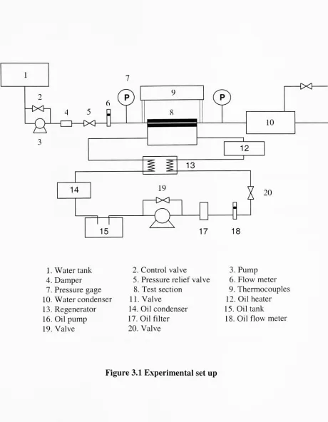
Figure3.1
Experimental
set
up
30
Figure 3.2
Overall geometry
of
the test
section
31
Figure 3.3
The geometry
of
the
mini-channel
of
waterside
35
Figure 3.4
Geometry
of
the
fin
36
Figure 3.5
Unit
cell of
fin geometry
37
Figure 3.6
The
effect of
Reynolds
number on
fraction
factor
(traditional)
41
Figure 3.7
Entrance
pressure
drop
and exit pressure
rise in
a
heat
exchanger
core
45
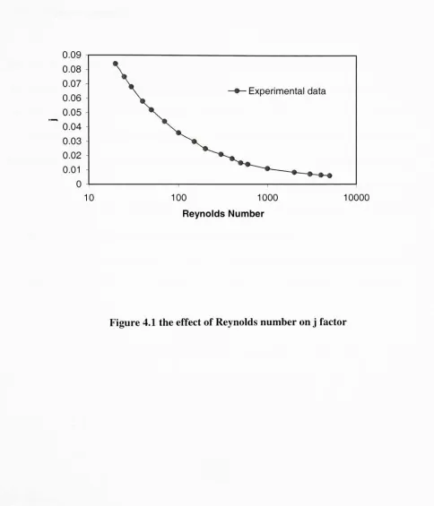
Figure 3.8
the
effect of
Reynolds
number on
fraction factor
46
Figure 5.1
the
geometry
of
the
mini-channel
65
Figure 5. 2
Reynolds
number vs.
total
pressure
drop
in
single-phase
flow
in
mini-channels with
six parallel channels
67
Figure
5.3
Reynolds
number
vs.
pressure
drop
in
mini-channels
with
six
parallel channels
67
Figure 5.4
Reynolds
number vs.
friction factor for
mini-channel
test
sections
with six parallel
channels
68
Figure
5.5
Details
of
the
manifold and
test
section channels
69
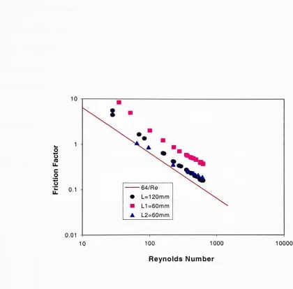
Figure5.6
Effect
of
the
mini-channel size on
friction factor
72
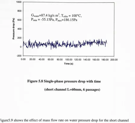
Figure 5.7
Single-phase
pressure
drop
with
time
(short
channel
L=60mm,
6
passages)
73
Figure
5.8
Effect
of mass
flow
rate of
water on pressure
drop
(short
channel
L=60mm,
6
passages)
75
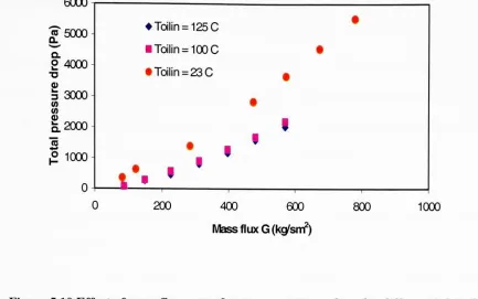
Figure
5.9
Effect
of mass
flow
rate
of
water on pressure
drop
for different
inlet
oil
temperatures
(short
channel
L=60mm,
6
passages)
76
Figure
5.10
Effect
of mass
flow
rate
of water on pressure
drop
for different
inlet
oil
temperatures
(long
channel
L=120mm,
6
passages)
77
Figure 5.11
Effect
of mass
flux
on
heat
transfer
rate
(long
L=
120mm,
6
passages)
Figure
Title
Page
Figure 5.12
Effect
of
mass
flux
on
heat
transfer
rate
(short
L=60mm,
6
passages)
79
Figure 5.14
Variation
of pressure
drop
with
time
inside
the
mini-channels
(short
channel
L=60mm,
6
passages)
81
Figure
5.15
Effect
of
oil
inlet
temperature
on
total
pressure
drop
for different
mass
fluxes (short
L=60mm,
6
passages)
82
Figure 5.16
Effect
of oil
inlet
temperature
on
total
pressure
drop
for different
mass
fluxes
(long
L=120mm,
6
passages)
83
Figure
5.17
Effect
of mass
flux
of water on
total
pressure
drop
for different
oil
inlet
temperature
(short
L=60mm,
6
passages)
83
Figure
5.18
Effect
of mass
flux
of water
on
total
pressure
drop
for different
oil
inlet
temperature
(long
L=
120mm,
6
passages)
84
Figure
5.19
Effect
of mass
flux
of water on exit
quality for different
oil
inlet
temperatures
(short
L=60mm,
6
passages)
86
Figure 5.20
Effect
of mass
flux
of water on exit
quality for different
oil
inlet
temperatures
(long
L=
120mm,
6
passages)
86
Figure
5.21
Effect
of water mass
flux
on
heat
transfer
rate
for different
oil
inlet
temperature
(short
L=60mm,
6
passages)
87
Figure5.22
Effect
of water mass
flux
on
heat
transfer
rate
for different
oil
inlet
temperature
(long
L=
120mm,
6
passages)
88
Figure5.23
Effect
of oil
inlet
temperature
on
exit
quality for different
mass
flux
of water
(short
L=60mm,
6 passages)
89
Figure5.24
Effect
of oil
inlet
temperature
on
exit
quality for different
mass
flux
of water
(long
L=
120mm,
6 passages)
89
Figure
5.25
Effect
of oil
inlet
temperature
on
heat
transfer
rate
of oil side
(short
L=60mm,
6
passages)
90
Figure
5.26
Effect
of oil
inlet temperature
on
heat
transfer
rate
of oil side
(long
L=
120mm,
6 passages)
Figure
Title
Page
Figure 5.27
Effect
of mass
flux
of water
on
heat
transfer
coefficient
of
the
mini-channel
(short
L=60mm,
6
passages)
94
Figure 5.28
Effect
of
mass
flux
of water
on
heat
transfer
coefficient
of
the
mini-channel
(short
L=120mm,
6
passages)
94
Figure 5.29
Effect
of
oil
inlet
temperature
on
heat
transfer
coefficient
of
the
mini-channel
(short
L=60mm,
6
passages)
95
Figure 5.30
Effect
of oil
inlet
temperature
on
heat
transfer
coefficient
of
the
mini-channel
(short
L=
120mm,
6
passages)
95
Figure 5.31
Comparison
of
the two test
sections
with
respect
to the
effect of
increasing
on
heat
transfer
coefficient
96
Figure 5.32
Comparison
of
the two test
sections with respect of
the
effect of
increasing
oil
inlet
temperature
on
heat
transfer
coefficient
96
Figure
5.33
Effect
of exit
quality
of
the
mini-channel
on
total
pressure
drop
across
the
mini-channel
heat
sink
(short
L=60mm,
6
passages)
97
Figure
5.34
Effect
of exit
quality
of
the
mini-channel
on
total
pressure
drop
across
the
micro-channel
(Long
L=
120mm,
6
passages)
98
Figure 5.35
Successive
Frames
(a)
through
(g)
at
2ms Intervals
of one
Channel
101
Figure 5.36
Successive Frames
(a)
through
(h)
at
1ms Intervals
of
one
Channel
102
Figure 5.37
Successive Frames
(a)
through
(h)
at
4ms Intervals
of
one
Channel
103
List
of
table
Table
Title
Page
Table 2.1
Summary
of single-phase studies
17
Table 2.2
Summery
of
Two-phase
19
Table 2.3
Summery
of
flow
pattern
22
Table 3.1
Hardware
51
Table 3.2
Software
51
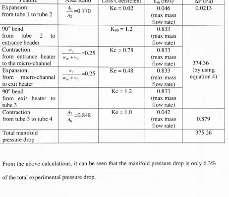
Table 5.1
Contributions fro different
pressure
drop
terms to the total
pressure
drop
in
mini-channel
test
section
Abstract
Flow
boiling
in
mini-channels
has been
the
most
recent
trend
in
high
performance
cooling techniques, in
spite
of
an
increased
pressure
drop. An
experimental
study
of
pressure
and
heat
transfer
characteristics
of
water
in
mini-channel
evaporators
was
carried out
in
this
study.
The
test
section
consisted
of
6, U-shape,
parallel,
mini-channels.
The
mini-channels
were
formed
by brazing
an
etched,
flat,
stainless steel plate.
The
hydraulic diameter
of a single
mini-channel
was
0.725
mm.
Distilled
water,
used
as
the
fluid
medium,
flowed in
the
mini-channels;
while
the
heating
oil
flowed
on
the
outside
of
mini-channel.
The inlet
temperature
of
the
water
was maintained at room
temperature
and
the
outlet pressure was
ambient pressure.
The
mass
flux
was
in
the
range of
87.36
kg/m~s
to
656.75
kg/m2s.
In
order
to
enhance
the
heat
transfer
of
the
oil
side,
offset-strip fins
were applied on
the
stainless
steel
surface
of
the
oil
side
channel.
Parafherm heat
transfer oil, the
fluid
medium,
was
used
on
the
oil
side.
The inlet
temperature
of
the
oil
channel
was
varied
through
a range of
100C
to
275C.
The heat
transfer
and pressure
drop
results were obtained as a
function
of
water
flow
rate
and
inlet
oil
temperature.
The
results
indicate
that the
heat
transfer
coefficient
on
the
water
side was
a
function
of
the
water
mass
flow
rate,
the
outlet steam
quality,
and
the
oil
two-phase
flow
region, the
pressure
drop
behavior
was
more
complex
since
a
higher
water
mass
flow
resulted
in
a
lower
average
quality in
the
evaporator.
The
vapor
generation phenomena
associated with
boiling
and
the
resultant
two-phase
flow
gives
the
pressure
drop
and
heat
transfer
2-10 fold.
The study
of
two-phase
heat
transfer
visualization
gives
more
detail
of
the
mechanism of
two-phase
flow
and
heat
transfer.
The capillary
phenomena
play
a
very important
role
in
the
small
size channel.
In
this study,
four
predominant
flow
patterns,
isolated
bubbles,
confined
bubbles,
slug flow
and
annular
flow
were observed.
As nucleating bubbles
were
generated
and
being
confined,
slug flow easily formed
at
lower
wall
temperatures
in
the
1
Introduction:
Since Tuckerman
and
Pease did
their
pioneering
experimental
study
of micro-channel
heat
transfer
in
1981,
the
micro-channel
has been found
useful
in many fields.
Many
scientists
have
studied
it further
to take
advantage of
its high heat
transfer
rates.
It
was
found
that the
characteristics of
the
small-channels
provide
a
very high
ratio of surface
area
to volume,
low
thermal resistance,
small
volume,
low
total
mass,
and
low
inventory
of
working fluids.
Additionally,
a
small
channel
leads
to
a
very high heat
transfer
coefficient
since
it
varies as a negative power of
the
hydraulic diameter
of
the
passage.
Thus,
mini-channels
tend
to
have
high
heat
transfer
coefficients,
leading
to
high-performance
curves on
the
heat
transfer-friction
power
plot,
despite
the
influence
of small
hydraulic diameter
on
the
pumping
power.
The literature
dealing
with
heat
transfer
and
flow
characteristics
in
small
channels
is
replete with
terms
describing
channel size
(e.g.,
micro-, meso-,
and
macro-,
etc.).
There is
no
unique
hydraulic
diameter
identifying
the
beginning
of
the
"micro"-channers
range.
In
this paper,
a mini-channel was
defined
as
having
a
hydraulic diameter ranging from
lum
to
lOOum,
and a meso-channel or
mini-channel
having
a range of
lOOum
to
1mm.
A
channel
with
a
hydraulic
diameter ranging from 1mm
-6mm
was
defined
as a
macro-channel,
and
anything larger
than
6mm
was considered
a
conventional
channel.
The heat
transfer
performance
of
the
mini-channel
is
similar
to
the
conventional channel
1.1 Single-Phase
Flow
In
the
single-phase
region,
no phase change
occurs since
the
wall
temperature
usually is
less
than
the
fluid
saturation
temperature.
The
mechanism
of
the
heat
transfer
performance
is
convection,
mainly forced
convection
of
fluid flow
over
the
channel.
In
this region,
surface
friction
and
the
convection
transfer
rates
depend strongly
on whether
the
boundary
layer is laminar
or
turbulent.
In
the
laminar
boundary
layer,
fluid
motion
is
highly
ordered and
it is
possible
to
identify
streamlines
along
which
particles
move.
In
contrast,
fluid
motion
in
the
turbulent
boundary
layer
is
highly
irregular
and
is
characterized
by
velocity
fluctuations.
These
fluctuations
enhance
the
transfer
of
momentum and
energy,
hence
increasing
surface
friction
as well
as
convection
transfer
rates.
Also,
the
fluctuations
creating
a
turbulent
boundary
layer,
provide
velocity,
temperature
and concentration
profiles,
which are
thinner
and
flatter
than
in laminar flow.
1.2 Two-Phase Flow
In
this region,
boiling
occurs
since
the
wall
temperature
is higher
than the
local fluid
saturation
temperature.
The
mechanism
of
the
heat
transfer
is bubble formation
at
the
inner
surface
of
the
heated
wall,
on
which,
a
liquid is flowing. Bubble
growth
and
separation are
strongly
influenced
by
the
flow
velocity.
Once
the
bubbles
that
appear at
the
surface grow and are
carried
into
the
main stream
of
associated
with
this
bubbly
flow
regime.
As
the
volume
fraction
of
the
vapor
increases,
individual
bubbles
coalesce
to
form
slugs of
vapor.
This
slug-flow
regime
is
followed
by
an annular-flow
regime
in
which
the
liquid forms
a
film. This film
moves
along
the
inner
surface,
while
vapor moves
at a
higher
velocity
through the
core of
the tube.
The
heat
transfer
coefficient
continues
to
increase
through
the
bubbly
flow
and
much
of
the
annular
flow
regimes,
however,
dry
spots
eventually
appear
on
the
inner
surface,
at which
point,
the
convection
coefficient
begins
to
decrease.
The
transition
regime
is
characterized
by
the
growth of
the
dry
spots until
the
surface
is completely
dry
and all
remaining liquid is in
the
form
of
droplets appearing in
the
vapor
core.
The
convection
coefficient
continues
to
decrease
through
this
regime.
There is little
change
in
this
coefficient
through the
mist-flow
regime,
until
the
point
at
which
all
the
droplets
are
converted
to
vapor.
The
vapor is
then
superheated
by
forced
convection
from
the
surface.
The
mechanism
of
two
phase
flow heat
transfer
performance
in
the
mini-channel
is
similar
to the
conventional
channel
(D>3-5mm). Due
to
capillary
phenomena,
however,
when
the
individual
bubbles
are generated at
the
heated
wall,
they
grow
easily
to the
size
of
the
channel
cross-section,
and
develop
into flow
patterns.
1.3
Applications
Mini-channels
as
well
as
micro-channels can
be
used
in many fields
such
as
fuel
cell
development,
the
electronics
industry,
high-energy
lasers,
avionics
systems,
central
2
Preview
Study
2.1
Single-Phase
Studies
In
this section, the
single-phase
characteristics
in
the trapezoidal channels,
rectangular
channels and
circular channels will
be
discussed.
The
summarized specific
information
of
the
studies
is
presented
in
Table
2.1.
Wu
and
Little
(1983)
used
trapezoidal
micro-channels
to
determine
the
friction factors
of
the
flow
of gases.
The
micro-channel width
varied
from 136
to
200um,
and
the
depth
from 28
to
65u.m
with
a
relative
surface
roughness
(based
on
peak-to-valley
surface
roughness
height,
e)
between
45
to
83um. Their
studies revealed
that the
friction factor
was
influenced
by
the
channel
roughness even
in
laminar flow. This
result
is
due
to the
changes
in
flow
cross section caused
by
the
large
roughness.
For laminar
flow,
the
ratio
between
the
value
of
the
experimental
friction factor
and
the theoretical value,
(f/fiam)>
was
found
to
lie in
the
range
1.3 (smoother
channels)
to
3.5
(very
rough
channels,
e/Dh=0.3).
Another
observation
was
that,
the
rougher
the
surface
of
the channel, the
earlier
the
transition
from laminar
to
turbulent
flow
(350<Rec<900).
Moreover,
the
normalized
friction
factor
f/fturb
for
turbulent
flow
(400<Re<
15000)
ranged
between 1.1
(almost
smooth
channels)
and
5
(very
rough
channels, e/Dh
=0.3).
Up
to
a
Re
=15000,
the
complete
turbulence
zone
in
which
the
friction
factor is independent
of
the
Re (as
shown
in
the
Moody
chart)
was
not
found.
As is
evident
from
this
study,
the
surface
Accurate
measurements of
surface roughness are
necessary
to
correctly interpret
the
data.
They
did
not measure
the
surface roughness
directly,
but
estimated
it using
the
Karman
equation
for
the
complete
turbulence
zone.
Wu
and
Little
(1984)
measured
heat
transfer
characteristics
for
the
flow
of
nitrogen
gas
in
heat
exchangers
used
for
micro-miniature
Joule-Thomson
refrigerators.
The
test
section
was a
trapezoidal channel,
and
the
Dh
of
the
channels
ranged
from 134
to
164
um.
The
transition
zone
from laminar
to turbulent
is
at
Re ranging from 1000
to
3000. The
average
h (based
on
the
fluid inlet
and
outlet
temperatures)
was
found
to
be larger for
the
channels with
heat coming from
two
sides
than
for
the
channel with
heating
from only
one
side.
Nusselt
numbers
in
laminar
flow
region
(Re<600)
were
lower
than
the
predictions of standard correlation.
For
600<Re<1000,
Nusselt
number was
higher
than
the
conventional
predictions.
They
used
asymmetrically
rough
channels
and
compared
their
results
to
a correlation
for
smooth
tubes.
Peng
et
al
(1994). investigated
the
flow
characteristics
and
the
forced-flow
convection
of
water
though
rectangular
channels
having
hydraulic diameters
of
133-367um
and aspect
ratios
(HAY)
of
0.333-1. The
measurements
indicated
that the
upper
bound
of
the
laminar
heat
transfer
regime occurred at a
Re
of
200
to
700
and
fully
turbulent
convective
heat
transfer
regime
was reached at a
Re
of
400
tol500.
The
transition
Re
decreased
with
the
reduction
of
the
meso-channel
dimensions. For
the
laminar heat
transfer regime, the
Nusselt
number was
found
to
be
proportional
to
Re062.
However,
it
should
be
noted
that
Nusselt
number
is
not
justified.
The
turbulent
heat
transfer
data
exhibited
a
relationship
between Nu
and
Re
similar
to that
found in
Dittus-Boelter,
but
with
a
different
empirical
coefficient.
Geometric
parameters
were
found
to
significantly
affect
the
heat
transfer
characteristics.
The
experiments
indicated
that the
laminar
convective
heat
transfer
had
a
maximum
value
when
H/W-0.75.
The
turbulent
heat
transfer
was
optimal
when
the
0.5<HAV<0.75. For H/W
around
0.5
in
small
channels, the
experimental
friction factor
was
found
to
be less
than the theoretical
value.
For
other aspect
ratios,
decreasing
the
micro-channel size resulted
in
a
flow
resistance
that
was
higher
than the
predicted
value.
2.2 Two-Phase
studies
In
this section, the two-phase
characteristics
in
the
V-shap
channels,
rectangular channels
and
circular
channels
will
be discussed. The
summarized
specific
information
of
the
studies
is
presented
in
table
2.2.
Experimental
study
was
conducted
by
Peng,
Hu
and
Wang
(1998)
to
study
the
flow
and
boiling
heat
transfer
characteristics
of
water
and
methanol
flowing
through
V-shape
micro-channels.
The
micro-channels
have hydraulic diameters ranging from 0.2
to
0.6
mm and
V-shape
groove angles
9
of
30
to
60. The fluid Re is from 210
to
630.
They
indicated
that
decreasing
the
micro-channel
hydraulic diameter delayed
boiling
initiation,
increased
heat
transfer coefficient,
and
increased
the
pressure
drop. The
experiments
also
showed
that
there
exists
both
an
optimum
hydraulic
diameter
and
an
optimum
groove
angle.
The
visualization
experiments
found that, if
there
was
a
good
seal
between
the
micro-channels
for flow
boiling
with
heat
fluxes
as
high
as
of
the
order
of
IO6
W/m2,
at which
fully
nucleate
boiling
with a
large
number
of
bubbles
would
be
expected
in
conventional
situation.
Extremely
high heat flux may
cause
fluctuating
liquid flow
and
blockage
of
the
micro-channel
inlet
if
a
large
number of
bubbles
form in
the
inlet
plenum.
Ravigururahan
(1998)
studied
two-phase
flow heat
transfer
characteristics
of refrigerants
in
micro-channel
heat
exchangers.
The
test
channels were
1mm depth
and
270um
width,
Two
channel configurations were
tested:
parallel
and
diamond. Subcooled
boiling
testes
were performed on
the
diamond
arrangement alone,
h increased
on
increasing
the
flow
rate
flow
inlet subcooling
greater
than
8C
and
decreased from 12000
to
9000 W/m2K
when
the
wall superheat was
increased
from 10C
to
80C. Similar
trends
were
observed
for
the
heat flux. In
saturated
flow
boiling,
h higher
than
for
macro-scale channel
flow
was
obtained
(Nu/Nuconv
=2.7
with
respect
to
the
Chen
(1966)
correlation
at
a
wall
superheat
of
10C).
The
saturated
flow
boiling
experiments
were
conducted
with
an
average
inlet subcooling
of
5C. h decreased
with
increasing
vapor
quality.
For
flow
rates
exceeding
125ml/min,
the
h
remained
approximately
constant
in
the
diamond
channel
heat
exchanger.
A
rapidly
with
an
increase in
h,
decreasing
marginally
when
the
heat
flux
was
reduced
and
increasing
with
an
increase
in
the
vapor
quality.
One
possible
explanation
for
this
apparently
counterintuitive result
is
the trend
of
increasing
heat
flux
with
increasing
wall superheat.
Coupled
with
the
weak
dependence
of
the
pressure
drop
Bowers
and
Mudawar
(1994)
studied
pressure
drop
and
CHF for R-113
flowing
through
multi-port circular
channels with
hydraulic
diameters
of
2.54mm
and
510um. Different
inlet subcooling
and
flow
rates
were
studied.
The study
revealed
flow
boiling
as
an
effective means
of
achieving high heat fluxes (q>200
W/cm2),
coupled
with
low flow
rates
(Q<65
ml/min)
and
low
pressure
drop
(AP
<
0.35 bar). The CHF did
not exhibit
dependence
on
the
inlet subcooling
at
low flow
rates,
which was attributed
to the
fluid
reaching
saturation
temperature
a short
distance
into
the
heated
section
of
the
channel.
The
authors
also
modeled
the
pressure
drop
through the
channels
using
a
homogeneous
two-phase
flow
assumption,
and were able
to
predict
the
pressure
drop
within
30%.
For
the
510um
micron
heat
sink,
acceleration accounted
for
about
75%
of
the total
pressure
drop,
compared
to
approximately 90% for
the
2.54mm heat
exchanger.
These
results are
not
surprising,
considering
the
low
mass
velocities,
resulting in relatively low frictional
losses.
Mertz,
Wein
and
Groll
(1996)
investigated flow
boiling
heat
transfer
in
narrow channels.
The
channels are
1mm,
2mm,
3mm
wide with
aspect ratios
of
up
to
2. The
experiments
are carried out
in
the
flow-boiling
mode
in
vertical
orientation.
Water
and
R141b
are used
as
working fluids.
Their
experiments
are
carried
out
under
saturation
conditions
at
pressures
of
1
bar
and
2 bar. Mass fluxes
of
50
kg/m2s,
100 kg/m2s
and
300 kg/m2s
are
employed.
Their
experiments
showed
that
for
all
tested
speci-men
the
boiling
performances
are
very
similar.
Best
result were obtained
for
channel
aspect
ratios
of
2x4
and at
higher
saturation
pressure
(2bar)
gives
better
results.
Optimum
mass
flux
seems
to
increasing
heat
flux,
the
boiling
in
the
channels
follows
the
well-known sequence
from
generation and
flow
of
isolated bubbles
to
generation of
confined
bubbles
and
slug flow
and
further
to
annular
flow.
Depending
on
the
different
channel geometries
the
heat flux
range varies
for deferent
channel
geometry
the
heat flux
range
varies
for different
boiling
modes.
For working fluid
water
and
geometry
with
wide
and
deep
channels
(M3x3,
M2x4)
a
distinct
nucleate
boiling
occurred,
which
changed
to
confined
bubble formation
and
then to
annular
flow. For
test
sections with smaller
channels
the
lifetime
of
the
single
bubbles
decreased,
and
for
some
test
sections
like Mlx2
and
Mlxl
it
was
very difficult
to
observe
single
bubbles. For working fluid R141b
smaller
bubbles
occurred,
and
the
flow
boiling
pattern
changed
already
at
low
heat fluxes
to
confined
bubbles
and
them to
annular
flow. Also for
test
sections
with
wider
and
deeper
channels
the
annular
flow
regime was reached at
low heat
fluxes
and existed
nearly
during
the
whole experiment
from
low
to
maximum
heat
fluxes. For
single-channel, the
flow
boiling
phenomenology
was
very
similar
to
that
in
the
multi-channel
configuration.
Kamidis
and
Ravigururajan
(1999)
investigated
single
and
two-phase
refrigerant
flow in
mini-channels.
The study
seeks
to
examine
the
flow
characteristics
of channels
in
the
1
to
5mm
diameter
ranges.
Four
heat
sinks
with
micro-channel
diameters
of
1.59mm,
2.78mm,
3.97mm,
and
4.62mm respectively have been
tested
for Reynolds
numbers
ranging from 190
to
1250.
They
obtained
that
for
all
test
sections
there
is
a
transitional
region
in
the
250-500
region
for Reynolds
number
with
the
pressure
drop initially
decreasing
and
them
exponentially
increasing
with
increasing
Reynolds
number.
The
The heat
transfer
coefficients
increased
gradually
with
Reynolds
number and
decreasing
channel size.
They
also
found
that the
critical
heat
fluxes
of
26
W/cm2were obtained
for
two-phase
flow for
a
wall
temperature
difference
of
18C.
Wei
Tong
and
Arthur E. Bergles
and
Michael K. Jensen
(1997)
investigated
pressure
drop
with
highly
subcooled
flow
boiling
in
small-diameter
tubes.
The
experiments
were
carried out
with
tubes
having
inside
diameters ranging from 1.05
to
2.44mm. Mass fluxes
ranged
from 25,000
to
45,000
kg/m2s,
exit
pressures
from 4
to
16
bar,
and
inlet
temperatures
from
22
to
66C.
Two
length-to-diameter
ratios
were
tested.
These
conditions
resulted
in
critical
heat
flux levels
of
50-80 MW/m". Their
experimental
results
indicate
that
mass
flux,
tube
diameter,
and
length-to-diameter
ratio are
the
major
parameters
that
alter
the
pressure-drop
curves.
Both
single-and
two-phase
pressure
drops
increasing
internal
diameter. Inlet
temperature
and exit pressure
has been
shown
to
have
significant
effects
on
two-phase
pressure
drop
but very
small
effects
on
single-phase
pressure
drop.
They
also
correlated
both
single-phase
and
subcooled
boiling
pressure
drops in
small-diameter
bubbles
under
different heat-flux
conditions.
2.3 Flow Pattern:
Kuznetsov
V.V.,
Shamirzaev A.S
(1999)
studied
two-phase
flow
pattern and
flow
boiling
heat
transfer
in
non-circular
channel with
a small gap.
The
channel
is 0.9mm-annulus gap
with
length
equals
to
0.4m. The working
fluid
is R318C.
They
found
that
flow
boiling
in
pattern.
For
subcooled
boiling
the
detachment
size
is less
than
the
gap
size.
For
saturated
flow
boiling
the
bubbles
trend to
amalgamation
and
it
forms
the
flow
with
confined
bubbles (Taylor
bubbles),
cell
flow
(annular-slug flow)
and
annular
flow. Liquid
plugs
at
cell
flow
collect
the
disturbance
waves and
the
entertainment was
not
observed.
The
total
boiling
suppression occurs
for
a
film
thickness
less
than
40
micrometers.
That
value
is
close
to the
bubble departure diameter
was observed
for flow
boiling
in
film. For
a
film
thickness
less
than
critical
one
the
forced
convection
occur with
a
small
heat
transfer
coefficient.
The
crisis
of
the
heat
transfer
was observed
for
a
complete
liquid
evaporation
on
the
heated
wall.
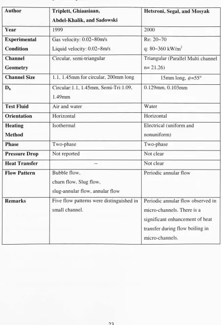
K. A.
Triplett,
S.
M.
Ghiaasiaan,
S.
I.
Abdel-Khalik,
D. L. Sadowski
(1999),
using
air
and
water
experimented circular micro-channels with
1.1,
1.45mm inner diameters
and
semi-triangular cross
sections with
hydraulic diameters 1.09
and
1.49
mm.
The
gas and
liquid
superficial
velocity
ranges were
0.02-80
and
0.02-8
m/s.
Five
major
flow
patterns
was
found
in
their
experiments:
bubbly,
slug,
churn,
slug-annular
and
annular shown
in
figure
15.
With
increasing
UGs
(which
leads
to
increasing
void
fraction)
the
bubbles
crowded near
the
channel
top
and
eventually led
to the
development
of
the
slug flow. At
high liquid
superficial
velocities
ULs
with
increasing
the
mixture
volumetric
flux
churn
flow
was established and
also
led
to
longer bubbles
and
shorter
liquid
slugs,
eventually
leading
to the
merging
of
elongated
bubbles
and
development
of
the
slug-annular
flow
pattern.
With
further increasing
UGs,
these
large
amplitude
solitary
waves
disappear
and
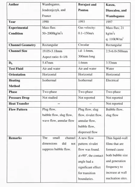
K. E.
Kasza,
T.
Diascalou,
and
M.
W. Wambsganss
(1997),
investigated
microscal
flow
visualization
of nucleate
boiling
in
small
channels:
mechanisms
influencing
heat
transfer.
Horizontal
rectangular channel with cross sectional
dimensions
of
2.5
x
6.0mm
and with
500mm
long
was
used
as
test
section.
They
used
video
camera and
furnish
the
high
picture
tats
and
magnification
needed
to
achieve
temporal
and
spatial
resolution
of
nucleate
bubble
growth and
behavior
the
channel.
They
presented
for high
and medium
heat flux
(q=110KW/m2,
mass
flux
=21kg/m2s) boiling,
individual
nucleation
vapor
bubbles
and
bubble/bubble
interactions,
when
confined
in
a small
channel,
produce
very
intense mixing
of
the
channel
flow because
of
the
rapid
bubble
growth
dynamics
and
increased
nucleation
frequency. When
large
vapor
slugs are
formed
at
higher fluxes
and
move
through
the channel, thin
liquid
wall
films
that
are
formed
cause
both bubble
size
and generation
frequency
to
increase
at wall nucleation
sites.
The
nucleate
boiling
heat
transfer
characteristics
are
exhibited
over
a
very
wide
range
of
conditions
in
small
channels and produce
higher heat
transfer
coefficients
that those
found in large
channels.
Lin
et
al.
(1998)
present
pressure
drop
characteristics
associated
with
different flow
patterns observed
during
air-water
flow in 2.1
mm
diameter
glass
tubes.
They
observed
significant
pressure
drop
fluctuations
for
annular
flow,
with
pressure
drop
value
fluctuating
between
0
and
6000 Pa for
a
gas
velocity
of
4.309
m/s and
a
liquid velocity
of
0.145
m/s.
They
did
not
observe
annular-slug
flow
pattern over
the
range of parameters
tested
in
their
experiments.
They
also presented
a
comprehensive
table
showing flow
Cornwell
and
Kew
(1996)
observed
flow
pattern
during
evaporation
of
R-113 in
two
parallel
multi-channel
geometries:
75
channels,
1.2
mm
wide
x
0.9
mm
deep,
and
36
channels
3.25
mm
wide
and
1.1
mm
deep.
They
observed
that there
were considerable
fluctuations in heat
transfer
as well
as
flow
behavior.
They
identified
three
flow
patterns:
isolated
bubble,
confined
bubble,
and annular-slug.
Isolated bubbles
were
small
bubbles,
which move
in
the
liquid,
while confined
bubbles completely filled
the
flow
cross-section.
For
each
region,
they
developed
a
heat
transfer
correlation scheme.
Hestroni
et
al.
(2000)
studied
the
evaporation
of
water
in
multi-channel
evaporators
consisting
of
21-26
parallel
flow
passages.
They
observed periodic
behavior
of
the
flow
patterns
in
these
channels.
The flow
changed
from
single-phase
flow
to
annular
flow
with
dryout in
some cases.
The
dry-out, however,
did
not result
in
sharp
increase
in
the
wall
temperature.
This clearly indicates
that there
is
still some
evaporating liquid film
on
the
channel walls
that
could not
be
observed
from
the
video
images.
They
also reported
the
presence
of vapor
phase
in
the
inlet
plenum.
The
channel
dimensions
studied
by
Table 2.1
Summary
of
single-phase
studies
Author
Wu
and
Little
Wu
and
Little
Year
1983
1984
Experimental
Condition
Re: 100-15000
Re:
400-20000
Channel
Geometry
Trapezoidal
Trapezoidal
Channel Size
(microns)
28x133,
36x149
89x312,97x572
Dh
(microns)
45.5-83.1
134-
164
Surface
Roughness
0.05
-0.30
0.01
Test Fluid
N2, H2,
Ar
N2
Orientation
Horizontal
Horizontal
Heating
Method
Not
applicable
Liquid
nitrogen
cooling
Phase
Single-phase
Single-phase
Rec
350
-900
1000
-3000
Pressure
Drop:
f/fconv
1.1-5.0
Not
studied
Heat Transfer:
Nu/NuConv
Not
studied
<1
at
Re<650(lam)
>1
at
650<Re<1000(lam)
1.38-1.69
(turb)
Results
The
friction factor
was
influenced
by
the
channel
roughness
even
in laminar
flow. The
rougher
the
surface
of
the
channel, the
earlier
the
transition
from
laminar
to
turbulent
flow.
The
average
h
(based
upon
the
fluid
inlet
and
outlet
temperatures)
was
found
to
be
larger
for
the
channel
with
heat
coming from
two
sides
than
for
the
channel
with
heating
from
only
one
side.
Remarks
High
relative
roughness
Asymmetrically
rough
surfaces.
Data
compared
to
smooth
tube
correlation
for laminar flow,
h
Table
2.1
Summary
of
single-phase studies
Author
Peng
and
Wang
Year
1994
Experimental
Condition
Re: 50-4000
Channel
Geometry
Rectangular
Channel Size
(microns)
100x200
aspect radio:
0.333-1
Dh
(microns)
133
Surface Roughness
Not
reported
Test Fluid
Water
r
Orientation
Horizontal
Heating
Method
Electrical
Phase
Single-phase
Rec
200
Pressure
Drop:
f/fconv
0.47(lam)
0.03(turb)
Heat Transfer:
Nu/NuConv
<1
(lam)
0.41(turb)
Results
The
transition
Re decreased
with
the
reduction
of
the
meso-channel
dimensions. Laminar:
NujuReO.62
Remarks
Significant
effect
of
H/W,
Dh
on
f,h. Smaller
Dn=>
lower
Rec
and
lower
transition
ranger,
h
based
on
Tin,
which
could
possibly
explain
the
Table 2.2
Summary
of
Two-phase
studies
Author
Peng
and
Wang
Ravigurautajan
Year
1998
1998
Experimental
Condition
Re:
210
-630Re:
4656-39900
Channel
Geometry
V-shape
Rectangular,
diamond
Channel Size
(microns)
H: 486-1459
W: 261-782
9:
30~60(degree),
6
1000x270
Dh
(microns)
200
~600
425
Surface
Roughness
Not
reported
Not
reported
Test Fluid
Water,
Methanol
R124
Orientation
Horizontal
Horizontal
Heating
Method
Electrical
Electrical
Phase
Two-phase
Two-phase
Rec
Not
reported
Not
reported
Pressure Drop:
f/fconv
Not
studied
Not
reported
Heat Transfer
Coefficient:
W/m2K
h:3xl03~3xl04
Not
reported
Results
Decreasing
the
micro-channel
hydraulic
diameter delayed
boiling
initiation,
increased heat
transfer
coefficient,
and
increased
the
pressure
drop.
h increased
on
increasing
the
flow
rate
for inlet subcooling
greater
than
8C
and
decreased from 12000
to
9000 W/m2K
when
the
wall
superheat
was
increased from 10C
to
80C.
Remarks
No
bubbles form in
the
micro-channel even when
the
heat
flux
is
very high if
there
is
a
good
seal.
For
flow
rates
exceeding
125ml/min,
h
remained
approximately
constant
Table
2.2
Summary
of
Two-phase
studies
Author
Bowers
and
Mudawar
Mertz,
Wein
and
Groll
Year
1994
1996
Experimental
Condition
Re: 86-768
Pressuenlbar,
2bar
Mass fluxes:
50,
100,
200,
300 kg/m2s
Channel
Geometry
Circular
Rectangular,
Half
circular
Channel Size
(nun)
2540,510
1,2,3
Aspect
ratios:
1-3
Dh(mm)
2540,510
1-3
Surface
Roughness
Not
reported
Not
reported
Test Fluid
R113
Water
and
R 14 lb
Orientation
Horizontal
Vertical
Heating
Method
Thick
film
resistor
Electrical
resistance
Phase
Two-phase
Two-phase
Rec
Not
reported
Pressure Drop:
0.7-
1.3
Not
reported
Heat Transfer
Coefficient:
W/m2K
Not
reported
h:500~4000
Results
Maximum
critical
heat
flux
decreases
as
D
decreases.
A
correlation
for
critical
heat flux
was
proposed.
Similar
boiling
performances.
Best
result: aspect
ratios of
2 '4. Higher
saturation pressure
better.
Optimum
mass
flux
seems
to
exist
between
about
200~300Kg/m2s.
Remarks
High
heat
flux
couples
with
low
flow
rate and
low
pressure
drop.
Flow form isolated bubbles
to
confined
bubbles
and
slug flow
and
Table
2.2
Summary
of
Two-phase
studies
Author
Kamidis
and
Ravigurautajan
Wei
Tong,
A. E. Bergles
Michael K. Jensen
Year
1996
1997
Experimental
Condition
Re: 190
-1250
Pressure: 4
to
16 bar
Mass
fluxes:
25,000
to
45,000
kgmA.
Channel
Geometry
Circular
Circular
Channel Size
(nun)
1.59,2.78,3.97,4.62
1.05-2.44
Dh(mm)
1.59-4.62
1.05|~2.44
Surface Roughness
Not
reported
Not
reported
Test Fluid
Refrigerant
Distilled
water
Orientation
Horizontal
Vertical
Heating
Method
Electrical
resistance
Electrical
resistance
Phase
Two-phase
Two-phase
Rec
250
-500
3000-20000
Pressure Drop:
0.5bar
1.5-6.0
bar
Heat Transfer
Coefficient: W/m2R
h:500-1600(single)
l.lxl04(two-phase)
Not
reported
Results
h increased gradually
with
Re
and with
decreasing
channel
size.
h
and
qCHF
increased
with
increasing
flow
rate
for
two-phase
flow
Pressure
drop
for both
single-and
two-phase
flow
is
proportional
to
mass
flux
and
length-to-diameter
ratio,
but
inversely
proportional
to
tube
diameter.
Remarks
Critical heat fluxes
of
26
W/cm2
were
obtained
for
two-phase
flow
for
wall
temp.
18 C
Correlation
of prediction
single-and
two-phase
friction
pressure
drop
in
small
diameter
tubes
was obtained
to
design
of
cooling
systems
of
Table 2,3
Summary
of
flow
pattern studies:
Author
Wambsganss,
Barajast
and
Kasza,
Jendrzejczyk,
and
Panton
Diascalou,
and
France
Wambsganss
Year
1990
1993
1997
Experimental
Mass flux:
Gas
velocity:
Mass
flux;
21
Condition
50-2000kg/m2s
0.1~150m/s
kg/m"s
q:
110kW/m2Channel
Geometry
Rectangular
Circular
Rectangular
Channel Size
19.05x3. 18mm
i.d:
1.6mm,
2.5x6.0x500mm
Aspect
ratio:
6-1/6
300mm
long
Dh
5.47mm
1.6mm
3.53mm
Test Fluid
Air
and water
Air
and water
Water
Orientation
Horizontal
Horizontal
Horizontal
Heating
Isothermal
Isothermal
Electrical
Method
Phase
Two-phase
Two-phase
Two-phase
Pressure
Drop
Not
studied
Not
reported
Not
reported
Heat
Transfer
- -Not
reported
Flow
Pattern
Plug
flow,
Plug
flow,
slug
Bubble
flow.
bubble
flow,
slug
flow,
flow,
rivulet
flow.
slug flow
wave
flow,
annular
flow
annular
flow,
bubble
flow,
dispersed flow
Remarks
The
small
channel
A
new
flow
Thin liquid-wall
dimensions
did
not
pattern: rivulet
films
that
are
suppress
bubble flow.
flow
was
found.
formed
cause
6>>90,
the
contact
both bubble
size
angle
had
a
and generation
significant effect
frequency
to
for
transition
increase
at wall
Table
2.3
Summary
of
flow
pattern studies:
Author
Lin, Kew,
and
Cornwell
Kuznetsov
and
Shamirzaev
Year
1998
1999
Experimental
Condition
Mass flux:
l-lOOOOkg/m's
Mass flux:
200-900 kg/
m2s
q:2~110kW/nr
Channel
Geometry
Circular
Annulus
Channel Size
i.d:
2.1mm,
470mm
long
0.9mm-annulus
gap
400mm
long
Dh
2.1mm
--Test Fluid
Air
and water
R318C
Orientation
Vertical
Horizontal
Heating
Method
Isothermal
Electrical
Phase
Two-phase
Two-phase
Pressure
Drop
Fluctuation
range:
Slug:-4255~8511Pa/m
Chum:-4255~6383Pa/m
Annular:-4255~14894Pa/m
Not
studied
Heat Transfer
tWured:
l~20kW/m-K
Flow Pattern
Slug
flow,
churn
flow,
annular
flow
Confined bubble
flow,
Cell
flow.
Annular flow
Remarks
Existing
flow
maps available
for flow
regimes
in
small
tube
except
the
boundaries
The capillary forces define
the
flow
pattern.
Decreasing
of
the
film
thickness
leads
to
suppression
of
boiling
heat
transfer
and a
transition
from
boiling
heat
[image:33.558.39.529.62.663.2] <