Rochester Institute of Technology
RIT Scholar Works
Theses
Thesis/Dissertation Collections
2003
Carbon nanotube catalysts: an approach toward
nanodimensional reactions
Mindy Gordon
Follow this and additional works at:
http://scholarworks.rit.edu/theses
This Thesis is brought to you for free and open access by the Thesis/Dissertation Collections at RIT Scholar Works. It has been accepted for inclusion
in Theses by an authorized administrator of RIT Scholar Works. For more information, please contact
ritscholarworks@rit.edu.
Recommended Citation
Carbon Nanotube Catalysts: An Approach Toward Nanodimensional Reactions
Mindy Gordon
July 2003
A thesis submitted in partial fulfillment of the requirements for the degree of
Master of Science in Chemistry
Approved:
Santhanam K.S.V.
Thesis Advisor
Terence C. Morrill
Department Head
Department of Chemistry
Rochester Institute of Technology
Copyright Release Form
Carbon Nanotube Catalysts: An Approach Toward Nanodimensional Reactions
I, Mindy Gordon, hereby grant permission to the Wallace Memorial Library, of
RIT, to reproduce my thesis in whole or in part.
Any use will not be for commercial use
or profit
.
Signature
Mindy Gordon
Table
ofContents
Abstract
i
Acknowledgments
iii
Publications
iv
List
ofFigures
vList
ofSchemes
viiList
ofTables
viiiList
ofEquations
viii1.
Introduction
1
1
.1
Structural Aspects
ofCarbon
1
1. 1. 1 Graphite
(amorphous)
1
1.1.2 Diamond
2
1. 1. 3 Carbon Nanotubes
2
1. 1.4 Synthesis of
Carbon
Nanotubes
3
1. 1.5
Structural
Representations
6
1
.2Electrical
Properties
9
1
.3Mechanical Properties
9
1
.4Purification
andFunctionalization
ofCarbon Nanotubes
10
1.4. 1 Chemical Properties
12
1.4.2 Applications
13
1.5 Nanoscience
15
1.5.1 Nanodimensional
Reactions
16
2.
Experimental
19
2.1
Chemicals
19
2.2 Instrumentation
19
2.2.1
UV-VIS Analysis
of
the
Reaction
19
2.2.2
GC/MS
Characterization
of
theProducts
19
2.2.3
FT1R of
Carbon
Nanotubes
andProducts
20
2.2.4
TGA of
Carbon
Nanotubes
20
2. 2. 5
Fluorescence Spectra
ofAzobenzene
andProducts
21
2.2.6
Atomic Absorption of Carbon Nanotubes
21
2.2.
7
pHof
theCarbon Nanotubes
21
2.3 Procedures
21
2. 3. 1
Functionalization of Carbon Nanotubes
21
2.4
Oxidation
ofAniline
22
2.5
Oxidation
ofp-Toluidine22
2.6
Oxidation
ofMethylamine
23
2.7
Oxidation
ofDiphenylamine
23
3. Results
andDiscussion
23
3.1
Characterization
ofCarbon Nanotubes
23
3. 1. 1 Fourier Transform
Spectroscopy
Studies
23
3. 1.2 Thermogravimetric
Studies
25
3. 1. 3
Scanning
Electron
Microscopic Results
26
3.
1. 4 Transmission
Electron Microscopic Studies
27
3.3
Atomic Absorption
ofFunctionalized Carbon Nanotubes29
3.4
Oxidation
ofPrimary
Amines
30
3. 4. 1
Aniline-Discovery
of
theEffect of
Carbon
Nanotubes
30
3. 4. 2
Influence of
Hydrogen
Peroxide Concentration
31
3.4.3
Role
of
Solvent
onOxidation
32
3. 4. 4
Test For Hydrogen Peroxide Inside
theNanotube
34
3.4.5
Possible Mechanisms
34
3.4.6
Catalysis
of
Carbon
Nanotubes
37
3.4.6.1
Estimation
ofAzobenzene Concentration
38
3.4.6.2
Azobenzene Diffusion Profiles
40
3.4.6.3
Suggestive Evidence For Reaction Inside
theNanotubes
42
3
.4.6.4Stereospecificity
ofAzobenzene
43
3.4.6.5
Oxidation
underInert
atmosphere43
3.4.6.6 Formation
ofNASH Product
44
3.5
Analytical Applications
46
3.6 Experiments
withRPI Carbon Nanotubes
50
3.7
Effect
ofSilica
andLight
52
3.8 Degradation
ofCarbon Nanotubes
52
3.9
Oxidation
ofp-Toluidine53
3.9. 1
Spectral
andKinetic
Features
57
3.10
Oxidation
ofMethylamine
67
4. 1
Principle
67
4.
1. 1
Proposed
Construction
68
4.2
Preliminary
attempts andResults
69
4.
2. 1
Simulation
of
theNanosynthetic Machine
69
4.2.2
Aniline
Oxidation
Reaction
71
4.2.2.1
Concentration
Dependence
ofAniline
90
4.
2. 3
p-ToluidineOxidative
Reaction
90
4.2.4
Methylamine Reaction
101
4.2.5
Oxidation ofDiphenylamine
101
4.3
Relevance
ofNanosynthetic Machine Concept in
Relation
to theExisting Technology
103
5.
Conclusions
1 04
Abstract
The
oxidations of aromatic and aliphatic amineshave
been
investigated
to evaluatethe
catalytic effect offunctionalized
multiwalled carbon nanotubes.
Aniline
oxidationby
hydrogen
peroxide produces
very low
yields ofazoxybenzene; similarly,
p-toluidine
oxidation produces azoxytoluene afterlong
time periods.When
functionalized
multiwalled carbon nanotubes are presentin
these
reactions,
the above oxidations produced unique productssuch as azobenzene or azotoluene within a short period.
The
course ofthe reaction
has been followed
by
GC/MS
that showed amass number of
198
corresponding
to
azoxybenzene(without
carbon
nanotubes)
or182 corresponding
to azobenzene(with
the
nanotubes).
The
first
stage of the oxidationis identified
asnitrosobenzene
formation
whichsubsequently
couples with theparent molecule to produce the azo compound.
UV-VIS
absorption
spectroscopy
showed no peakin
the
absence ofthe
carbon
nanotubes;
in
contrastto adistinct
peak at347
nmwhenthe
reaction
is
catalyzedby
carbon nanotubes.The
GC/MS data for
the/7-toluidine oxidation showed a mass spectral peak at a mass
number of
226,
corresponding
to
azoxytoluene,
whichis
replacedby
210,
corresponding
toazotoluene,
whenthe
reactionis
the
UV-VIS
absorptiondata
showed an azotoluene peak at464
nm.To
reduce the unwanted product contributioncoming
from
the
outer
solution,
a carbon nanotube column was configured.In
this
situation
100%
azobenzeneformation
was obtained when anilinewas oxidized.
The
efficiencies ofthedifferent
columnsrangefrom
50-97%
for
the
p-toluidine oxidation reaction.The
oxidations ofdiphenylamine
and methylaminehave
alsobeen
carried outin
the
column configuration to understand the mechanisms.
The
resultssuggest
the
feasibility
ofconstructing
a nanosynthetic machinefor
Acknowledgments
My
advisor,
Dr. KSV
Santhanam,
for his
ideas,
patienceanddirection
My
committee:Dr. T.C.
Morrill,
Dr.
G.
Takacs
andDr. M. Miri
for
theirguidanceand encouragement
Tom Allston
for
alwaysbeing
aroundto
help
The RIT
Chemistry
Department for providing
thefunding
for
theresearchDr. P. Ajayan
atRPI
for
carbonnanotubes andallowing
usto
usetheSEM
andTEM
Dr. D.D.L.
Chung
attheUniversity
ofBuffalo
for
the
honeycomb
graphiteMy family
andfriends for
all oftheir support-1
couldn'thave
made
it
withoutany
ofPublications
(Refereed
Journals)
M.
Croston,
J.
Langston,
R.
Sangoi,
andK.S.V.
Santhanam,
"Catalytic Oxidation
ofp-Toluidine
atMultiwalled
Functionalized Carbon
Nanotubes",
J. Internal
Nanoscience,
1(3-4),
277-84
(2002)
-A
special
issue
oncarbon nanotubes.M.
Croston,
J.
Langston,
G.
Takacs,
T.
Morrill,
M.
Miri,
K.S.V. Santhanam
andP.
Ajayan,
"Conversion
ofAniline
to
Azobenzene
atFunctionalized Carbon Nanotubes: A
Possible
Case
of aNanodimensional
Reaction",
J. Internal
Nanoscience, 1(3-4),
285-94
(2002)
-A
special
issue
on carbon nanotubes.Posters/Presentations
M.
Croston,
J.
Langston,
G.A.
Takacs,
T.C.
Morrill,
M.
Miri,
andK.S.V.
Santhanam,
Oxidation ofAniline
Catalyzed
by
Multiwalled
Carbon
Nanotubes,
poster,
ACS meeting
-
Rochester
division,
October 2001
M.
Croston,
J.
Langston,
R.
Sangoi,
andK.S.V.
Santhanam,
Catalytic Oxidation
ofp-Toluidine
by
Multiwalled Carbon
Nanotubes,
presentation,
201stECS
meeting,
Philadelphia, PA
May
2002
M.
Croston
andK.S.V.
Santhanam,
Concept ofNanosynthetic Machine
withFunctionalized
Carbon
Nanotubes,
poster,
ACS meeting
-Rochester
List
ofFigures
Figure
1.
MWCNT
carbon arcsetup
3
Figure 2.
Apparatus for
thepreparation ofMWCNT
by
pyrolysis4
Figure 3. Laser
ablation apparatusfor
the
preparationofSWNTs
5
Figure 4.
Single-walled
carbon nanotube6
Figure 5. Multi-walled
carbon nanotube7
Figure 6.
Helicity
of a carbon nanotubes7
Figure 7.
Helicity
of carbon nanotubes8
Figure 8. Apparatus for
the thermalannealing
ofCNTs
11
Figure 9. Irradiation
apparatusfor
purifying
nanotubes12
Figure 10. Carbon
nanotubetransistorfrom IBM
14
Figure 11. Reaction
inside
a carbon nanotube16
Figure 12. FTJR
analysis ofcarbonnanotubes priortofunctionalization
24
Figure 13. FTIR
analysis ofcarbonnanotubesfollowing
functionalization
24
Figure 14. TGA
graph ofCNT
priortofunctionalization
25
Figure 15. TGA
spectrum ofCNT
afterfunctionalization
26
Figure 16. MWCNT
carbon arc methodsetup
27
Figure 17. TEM
analysisofclosed carbon nanotube28
Figure 18. TEM
analysis of afunctionalized
carbon nanotube28
Figure 19. Photograph
of reactionin
cuvettes31
Figure 20.
1:1 Aniline:hydrogen
peroxidein
acetone reactions33
Figure 21. Azobenzene
in
acetonitrile reference spectrum37
Beer's
Law
plotfor
cis-andtrans-azobenzene39
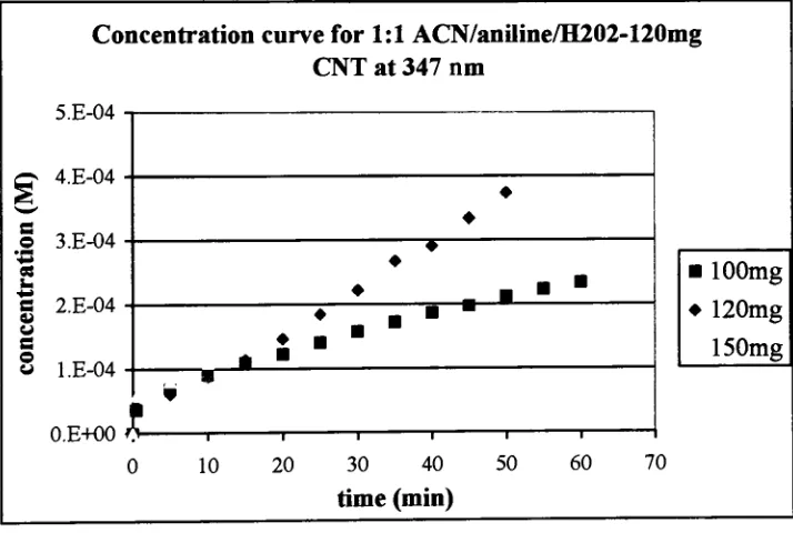
Figure
24.
trans-Azobenzene
concentrationvs.time
for
varying
amounts of
CNT
40
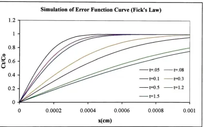
Figure 25.
Simulation
ofFick's
Law
errorfunction
curvefor
the
diffusion
of reactants
into
the
nanotubes and products out ofthe
nanotubes41
Figure 26. Extraction
ofthe solutioninside
the
nanotubes42
Figure 27.
1M
aniline and1M
hydrogen
peroxidein
acetonitrile monitoredevery
five
minutesfor
onehour
-convection method
46
Figure 28. Breakdown
ofCNTs
in
hydrogen
peroxide53
Figure 29. Simulation
ofp-toluidine reaction54
.Figure
30.
/?-Toluidinewithhydrogen
peroxide controlsolution(0-50min)
58
Figure 31. Time-dependent
absorbance ofp-toluidinereaction withCNT
59
Figure 32.
Linearity
ofthe
growthof p,p'-dimethylazobenzenewithtime60
Figure 33. Comparison
ofGC/MS
results of1
:1
p-toluidinereactionwith
hydrogen
peroxide61
Figure 34.
p'p-Dimethylazobenzene reference spectra62
Figure 35. Kinetic study
of1
:1
/?-toluidineto
hydrogen
peroxidereaction66
Figure
36. Proposed
construction of nanosynthetic machine68
Figure 37. Product
of aniline reactionfrom
simulatednanomachine
-first
collection72
Figure 38.
GC
spectrum of nanotube column collection80
Figure
39. Mass
spectrum ofthe
first
collectionfrom
the
nanotube column81
Figure 41.
UV-VIS
analysis of nanomachine product83
Figure
42.
Analysis
ofO2
saturation of acetonitrile88
Figure 43.
Analysis
ofN2
saturation of acetonitrile89
Figure 44.
UV-VIS
spectra ofp-toluidinecollection vs. controlfor
1
M
:1 M
solution94
Figure 45. UV-VIS
spectra of/?-toluidine collection vs. controlfor
2M: 1M
solution95
Figure 46.
p-Toluidine concentrationdependence
on azotoluenepeak96
Figure 47.
%Conversion
ofp-toluidine296nm
peak99
Figure 48.
Azotoluene
formation in
nanomachine99
Figure 49.
Nanomachine
collectionfrom diphenylamine
reaction102
List
ofSchemes
Scheme 1.
Outline
of reaction mechanismfor
thecontrol solution.35
Scheme 2.
Side-product formed
whenaniline andperoxide reactin
acetone.35
Scheme 3.
Outline
ofthe carbon nanotubereaction36
Scheme 4. Reaction
mechanismforp-toluidine
in hydrogen
peroxidecontrol solution
56
Scheme 5. Side-product
of/?-toluidinereacting in
acetone56
Scheme 6. Mechanism
of/?-toluidine reactionin
the
presence ofFMWCNT
57
Tables
Table
1.
pH ofFunctionalized
Carbon Nanotubes
29
Table 2. Aniline Detection
Limits
47
Table 3.
GC/MS
Data
ofthe
Catalysis
ofCNTs
48
Table 4.
GC/MS
Data
from Aniline
Reaction
49
Table 5. Comparison
ofRPI
andDEAL Nanotubes
51
Table 6. Comparison
ofKinetic
vs.Convection Method for
/j-Toluidine
Reaction
63
Table 7. Measurements
for
Carbon Nanotube Columns
70
Table 8.
Specifications
for Aniline Reaction
73
Table 9.
GC/MS Analysis 22h
afterCollecting
from
Nanomachine
75
Table 10.
Specifications for
/?-ToluidineReaction
90
Table 11. GC/MS Analysis
ofp-ToluidineCollections
92
Table 12. Concentration
ofAzotoluene
in Samples
withVarying
Concentrations
of^-Toluidine97
Table 13. Concentration
ofAzotoluene from 0. 1M
/?-ToluidineSamples
98
Table 14.
Efficiency
ofCNT Column
100
List
ofEquations
Eq. 1 Beer's law
equation39
Eq. 2 Fick's Law
ofDiffusion
41
1.
Introduction
The
synthesis offullerenes
and carbon nanotubesmay
be
considered as one ofthe
important discoveries
ofthe 20thCentury.
Kroto,
Curl
andSmalley (1)
pioneered theeffort when
they
began studying
a new allotrope ofcarbon calledthe
fullerene.
Another
turning
pointin
the
history
ofthe
chemistry
of carbon came with thediscovery
ofthe
tubular structure of carbon
by
Iijima
[2],
whichis
rapidly
being
investigated
for
materialstructure,
strength and catalytic properties.This
thesisis devoted
to theunprecedentedstudy
of catalytic properties of carbon nanotubes sin organic oxidative reactions whichmay
be
amenablefor
the
construction of nanosynthetic machinesfor
organicpreparations.
1.1
Structural Aspects
ofCarbon
There
arefour different
types
of graphite structures that willbe discussed:
diamond,
planargraphite,
buckminsterfullerenes
and carbon nanotubes.Diamond
existsas a
face-centered
cubic unit cellconsisting solely
of carbon atoms.Planar
graphiteconsists of planes of carbon atoms arranged
in
hexagons
whichlayer
each other.Graphite
seems tobe
"slippery"because
the planes canbe easily
separatedfrom
andmoved across each other.
This
is
why
graphiteis
usedin
pencils.The
buckminsterfullerene
is
spherically
shaped withthe
carbon endsforming
a pentagon toclose
the
sphere.Nanotubes
areformed in
somewhatthe
samefashion,
either single ormultiple graphitic planes are rolled
into
atube
with carbon pentagonsexisting
asthe
end1.1.1
Graphite
(amorphous)
Graphite
bonding
is
sp2hybridized
and exists as aflat
plane andhas
a3-fold
coordination system
[3].
1.1.2
Diamond
Whereas
graphiteis
sp2hybridized,
diamond
existsassp3
hybridized
carbonin
afour-fold
coordinated structure[3].
The C-C
bond distance
for diamond
is
larger
thanthatof graphite
due
to theweakerforces
between
the
atoms[3].
1.1.3
Carbon
Nanotubes
Multiwalled
carbon nanotubeshave diameters
from 10-50
nm and canbe 10
urnin length
orlonger.
Multiwalled
nanotubeshave
adensity
of1-2
g/cm3and a
very large
surface areaof
10-20
m2/g.Single
walled nanotubeshave
diameters
ofl-1.4nm
and canbe
aslong
as100
urn.Whereas
multiwalled nanotubebundles
arestraight,
singlewallednanotube
bundles
are curled andlooped.
Carbon
nanotubes can existin
threedifferent
orientationsthat affect their electrical properties:
zigzag,
armchair andchiral,
orhelical
[4].
Zigzag
nanotubes can either act as semiconductors ormetals,
armchair tubes aremainly
semiconductors and chiraltubes
areprimarily
metallic.One
ofthe
mostpromising
characteristics of carbonnanotubes,
other thanthat
they
canbe
conducting
is
that
they
canbe ballistic
conductors,
which meansthat there
willbe
noscattering
ofelectrons
[5].
They
alsohave
the
highest
currentdensity
ofany
known
material at 108A/cm [6].
Carbon
nanotubes areapproximately
100
times
stronger than steel with astrength of
60,000
psi.They
are alsovery
light
with adensity
of1.33-1.4
g/m3
Nanotubes
canbe
very
elastichaving
aYoung's Modulus
of1500
GPa
[7].
They
alsohave
ahigh
thermalconductance,
whichhas been
measured at -2000W/mK
at roomtemperature
[8]
and,
they
have
electrical conductance properties comparableto that
ofcopper
(5.9x1
07Qm)
[9].
When
nanotubes aremade,
they
form bundles
ofthemselvesthat
contain allthree
orientations ofthenanotubes.Researchers
atIBM
have developed
amethod of
separating
the
metallicCNT
from
thesemiconducting
CNT for
usein
singlecarbonnanotube
transistors
[10].
1.1.4
Synthesis of
Carbon
Nanotubes
There
are nowmany
different
waysin
which carbon nanotubes canbe
synthesized.
The
single walled tubesaregenerally
madeby
laser
ablation of a graphiterod
using
anickel or palladium metal catalyst.MWCNTs
aregenerally
preparedby
thecarbon arc method
in
the presence ofhelium
orhydrogen
gas.In
thiscase,
no metalcatalyst
is
needed.A. Anode B: Caihooe C:Collarette I): Deposit I 11eh-like\ul F.Soul (': DCpower
supph H Walcr-cooled
[image:18.484.94.389.416.630.2]doublewall reav'Un
The
carbon arc methodfor
producing
nanotubesis
shownin
Figure 1 [11].
The
cathodeand
the
anodearehoused in
adouble-walled
water-cooled condenser.When
a20-25
V
DC
arc currentis
passed acrossthe
anode to the cathodein
the
presence of30-500 Torr
of
H2
orHe2
gas,
at2500-3000
C,
the
cathodelength
begins
to
decrease
andCNT
areformed
[11].
Soot
is
collecteddown
atthebottom
ofthe
vessel.The
cathodeis
removedand
the
multiwalled carbon nanotubes are collected.MWCNT
can alsobe
formed
by
pyrolysis.
Quartztube
Furnace
Bubbler
&
[Thermocouple
ICA
[image:19.484.144.341.278.421.2]t
Figure 2.
Apparatus
for
thepreparation ofMWCNT
by
pyrolysis 12This
apparatus shownin Figure 2
consists of a quartztube with aninner
diameter
of20
mmand a
heating
zone of200
mm[12].
Acetylene
is
passedthrough
aliquid
Fe(CO)s
bubbler
at300
seemusing
argon as a carrier gasflowing
at30
seem[12].
The
gases andthe
catalyst are thenintroduced into
the
quartztube
andheated
at750-950
C for
30
minutes
[12].
The
furnace
is
then cooledto
roomtemperature
atanAr
flow
rate of500
seem
[12].
The
nanotubes arethen
collected.SWCNT
can alsobe
producedby
the
arcThis
metal canbe in
the
form
ofCo, Co/Ni,
Co/Y, Co/Fe, Ni/Y,
Ni/Fe
withNi/Y giving
the
best
results.These
catalysts promotethe
growthofthe
singlewalled structures.The
most common methodof
preparing SWNTs is
by
laser
ablation.Figure 3
showsthe
laser
ablation
apparatus,
which consists of a60
cmlong
quartztubewith an outerdiameter
of3.6
cmand aninner diameter
of2.7
cm[12].
A
target
(~5um
in
diameter)
consisting
of acompressed
graphite, Ni
andCo
powderis
placedinside
the
quartztube
at atemperatureof
1200
C
[12].
Argon
gasis introduced into
thequartztubeat a rate of0.2
L/min
and apressure of
700 Torr.
A Nd:Y
pulsedlaser beam
is
then shown ontothe
target andbombards
the
target surfacewith150
pulses oflight
[12].
The laser
has
awavelength of532
nm with a pulsewidth of6-7
ns and afrequency
of10
Hz
[12]. The beam
currentis
2 J/xm
with adiameter
of2
mm[12].
Once
thelaser
ablates thetarget,
the nanotubesare collected on awater-cooledcopper collector.
hjmaceat
1,200' Celsius
\
water-cooled^^^ copper co&edor all / "
\
1
argon gasm#>-:
*S^^^" ~Tfi^A^^*..V
' '""zniHcT{^sS***^ft P|P\
\ narwtube leH" growingetongfipof collector
grapfaletarget
neodymkjm-vflnunv
sJuminum-gamellaser
Fig. h.\. Singl'--wallednanotu!**>procuced in a quartz luhr-hcai.-d"
U, 1200'C hj the as^r vapor12 ation method, using a
fcraphit.*-larjl<Mandarooli-dcollectorfornanoubcs[95].
Figure 3. Laser
ablation apparatusfor
the
preparation ofSWNTs
12an
iron
oxide catalystis
prepared.Methane
is
decomposed
in
afurnace
at1000
C in
thepresence of
the
iron
oxide catalyst[12].
The
iron
oxide catalystis
preparedby
impregnating
alumina nanoparticlesin
methanol withFe(N03)2-9H20
at roomtemperature
for 1 hr [12]. The
solventis
then evaporatedat80C
andthe catalystis
thenheated
and groundinto
a powder.The
alumina/iron oxide catalystis
then placedin
aquartztube and
heated
at1000
C
with anAr flow [12]. Methane
is
thenintroduced into
the
quartztube
at aflow
rate of6150
cm3/min at1.25
atm pressure[12].
After
lOmin,
the methane
is
thenpurgedbe
reintroducing Ar [12]. The CVD
processhas
been
studiedto provide the optimum conditions
for
CNT
growth.Other
carrier gas/catalystcombinations
have been
usedincluding
n-hexane/ferrocenethiocene
used atRPI
[13].
1. 1. 5 Structural
Representations
Single-walled and multi-walled carbonnanotubes are shown
in Figures 4
and5.
Single-walled nanotubes consist of carbon atoms arranged
in
ahexagon
and rolledinto
atube.The
multiwalled carbon nanotubein Figure 4
consistsbasically
of concentricsingle-walled nanotubes.
R
i^t i^^i^^ i^%i^i i^i i^Qii^^i iSFigure 5.
Multi-walled carbonnanotube.15If
the
nanotubein
Figure 5
was opened andlaid
on aflat
surface,
it
wouldlook like
Figure 6 (a
andb),
aflat
graphene sheet.Figure 6
(b)
showshow
thehelicity
of acarbonnanotube
is
determined.
(ah.
(b)
-^. . , , A
_' .}
M a a. ,jfc _a
> a m a a >^c-50
"/'
^ * a 5 . l7i-.q:
:
! I J IS .17! SO
'
15 1 ?2ik7 ->k> f:metal '^enucorxJuctor
Figure
6.
Helicity
ofacarbon [image:22.484.132.359.342.634.2]The
helicity
is defined
by
the
m and nindices in
parenthesesonthe
diagram
(n,m)
[11].
When
m and n areequal, the
nanotubes are saidto
be
in
armchair[11]
configuration.When
mis
equal tozero,
thenanotubes areconsideredtobe
zigzag [1 1].
If
n and m aredifferent from
each other and mis
not equalto zero,
the nanotubesare chiral[11].
All
armchairnanotubes are metallic as shownonthe
diagram
andzigzag
tubes can eitherbe
[image:23.484.93.392.252.550.2]metals or semiconductors
[11].
Figure 7.
Helicity
ofcarbonnanotubes.nFigure 7
shows nanotubesofdifferent
helicities:
(a)
represents an armchairnanotube,
(b)
zigzag
tubes
areperfectly
symmetrical throughout the nanotubewhereas chiraltubes
arenot as can
be
seenin Figure 7 [1 1].
When
nanotubes areformed,
they
have
endcaps onboth
ends ofthe tube.
Once
they
arepurified,
the
endcaps arebroken
off asis
shownin
Figure 7. This
concept willbe discussed in
moredetail
in
anupcoming
section.1.2
Electrical Properties
Carbon
nanotubes can act either as metallic orsemiconducting
tubesdepending
on their geometry.
For
typical metallicsystems,
electrons can movefrom
one metalto
the next quite easily.
In
the case ofCNT; however,
because
they
possess suchdifferent
electrical
properties,
electrical current will not alwaysflow easily from
onetube to
the
next
[3].
Introducing
aSchottky
barrier
into
the nanotube(bending
the
nanotube at onepoint),
allowsthe
flow
of electrical currentto
continue[3].
Nanotubes
possessthese
defects
whenthey
are made andthey
can alsobe
formed
by inducing
a rotation ofbonds
between
twohexagons
to
form
afive-fold
ring
and anadjacent seven-foldring
[3].
This
allows a single nanotube
to
possessboth semiconducting
and semi-metallic character[3].
1.3 Mechanical Properties
Carbon
nanotubeshave
excellent mechanical propertiesdue
to
theirlow
density
of
defects [16].
The Young's
modulus ofCNTs (reported
previously)
is higher
than
tubes
composed of otheratoms[16]. This
valueonly slightly
depends
onthe
diameter
ofthe
nanotubes anddepends
on thedegree
ofsp2
hybridization
[16].
The Young's
modulus
is
highest
for
aflat
graphene sheetdue
to the
fact
that
folding
the
sheetinto
ananotube would
distort
sp2
ratio
(v)
of a nanotube alsodepends
onits
diameter,
but
is
dependent
onchirality
aswell[16].
Planar
graphitehas
aPoisson
ratio of v=0.
17,
armchairtubeshave
a v=0.
14,
andother chiralities range
from
v=0.18-0.19
[16].
When
stressis
appliedto nanotubes,
both
thin and thick-walled nanotubes exhibit compressive strengths one order ofmagnitude
higher
thanany known
fiber [16].
Zigzag
and armchairnanotubes arethe stiffest at0
K
[16].
Nanotubes
are alsovery
flexible [16].
When
subjectedto
large
amounts ofdeformation,
the nanotubes switchinto different
shapesreleasing
energy [16].
This
canbe
reversed andis
causedby
the
ability
ofsp2
hybridized C-C
bonds
toreversibly
changehybridization,
to sp3in
thiscase,
whendeformed
out ofa plane[16].
1.4
Purification
andFunctionalization
ofCarbon Nanotubes.
There
aremany
different
methodsfor purifying
andfunctionalizing
CNTs.
No
matter what method
is
used to produceMWNT
orSWNT,
the sootis
not100%
nanotubes.
As
a matter offact,
thepurity
ofthe sample canbe
between 10-90%.
The
CNTs in
the sample comein
threedifferent forms.
They
can eitherbe completely
closedtubes,
have
oneend open orhave both
ends open.The
purposeofpurifying
theCNTs is
toremovemost orall ofthe excessamorphous graphite material and
to
openboth
ends ofall of
the
nanotubesthat
arepresent.This
is
usually
done
in
the
presence of astrong
acidfor
approximately
12
hrs.
The
acidsinvolved
canbe
hydrochloric,
nitric and sulfuricacid.
In
most ofthese cases,
the ends are openedby
oxidating
the
carbonsin
the
pentagon
rings
of the endcaps asthey
canbe
easily
oxidizeddue
to
their geometry.When
this occurs,
carbonyl groupscanbe
found
atthe
dangling
carbonbonds
left
onthe
[17].
thrraoooupk
team
Intolute
<
lt
/heitar 1
TtnrMWNTi wtrrhite
r
(4K)
Figure
8.
Apparatus for
the
thermalannealing
ofCNTs.17
The
apparatusin Figure 8
represents onethatis
usedtopurify
thenanotubesby
thermalannealing.
The
cathodedeposit is
placedin
theinner
tube of thefurnace
andis
constantly
rotated at30
rpm.The
temperature
is fixed
at760
C
throughout.In
thiscase,
most ofthe carbonaceous material was removed and theweight was reduced
to
40%
ofthe original
[17].
Purification
ofMWNT
by
intercalation
ofCuCh
[18]
has
alsobeen
reported.
Nanotubes
can alsobe
purified and oxidizedusing
ozone[19].
In
gas-phaseozone
oxidation,
CNTs
are placedinto
a vertical reactorcontaining
a mixture of ozoneand oxygengasesand
heated
at150-200
C
for 30-90
min[19]. Liquid
phase oxidationsperformed
by
suspending
the
CNTs in
an acidic solution(CIO4",
Mn04*
or
H2O2)
along
with the oxygen/ozone gas mixture and
heated
at60-70
C
for 24 hrs [19].
In
both
ofthese cases,
theendcaps,
andany
kinks
or steps thatmay
occurin
the nanotubesthemselves,
arethefirst
tobe
oxidized andthebonds broken. Other
purification methodsw aler
IN
S=3
Figure 9. Irradiation
apparatusfor
purifying
nanotubes.20Figure 9
showsthe apparatusfor
thistype
of purification.The
cathodedeposit
from
thecarbon arc method
is
placeddirectly
in
the path ofthe
infrared beam.
Here,
it is
irradiated
for 30
min at500
C
in
air.The
productwasaspongy
square ofMWNTs
witha surface area of
10
mm2
and
0. 1
mmthickness[20].
1.4.1 Chemical Properties
The
chemical properties of carbon nanotubes are nowbeing
extensively
explored.Only
oneendof acarbonnanotubeis
openasit
exists afterit is
made.The
other end canbe
opened, exposing
the
nanotube to thepossibility
offilling
it
with moleculesthereby
acting
as a vessel.They
alsohave
ahigh
specific area which suggeststhat
many
molecules can
be
adsorbed ontothe surface ofthe
tubes.As
the
nanotubes areopened,
they
can alsobe
functionalized
-other molecules can
be introduced
to the
ends ofthe
carbon chains.
Carbon
nanotubes can also act aselectrodes,
increasing
the
rate of1.4.2
Applications
The
potential applications are numerousbased
onthe
extraordinary
electrical andmechanical properties
that
carbon nanotubes possess.Some
recent advances andimportant
research areas arediscussed
here.
It
has been
notedthat
CNTs have
the
ability
to
conductwaterby
capillary
action,
thesame
way
that
kidneys
and other smallblood
vessels movewater[22]. There
aretwomajor
implications
here.
First,
nanotubes wouldbe
extremely
valuablein
biological
systems.
This
providesthe
potentialfor
artificialorgans,
such askidneys,
andrecently,
scientists
have
been
determining
whetherCNTs
canbe
used as artificial muscles[23].
This
alsoimplies
that
CNTs
can act as carrier vessels or"nano
test
tubes"
Small
molecules
in
solution can enterinto
the
CNTs,
ashas already been
shownby
de
Heer,
etal.
CNTs
werefilled
with gaseous or solution-phase metals which weredecomposed
to
solid metals
inside
the
CNTs
[24].
CNTs
can alsobe
usedin
transistors
anddiodes.
They
arevery
small andthe
electronic properties are perfectfor
these types ofdevices
because
electrons can movefreely
within them withlittle
or no scattering.IBM
has
drain
electrode source
electrode
' (SO
.
^
WaWr^
i
t
fe
F
^^L^g,e
^
Figure 10.
Carbon
nanotubetransistorfrom
IBM
10They
canalsobe
used asfield
emittersfor flat-panel
displays.
Many
scientists,
recently,
have
been
testing
nanotube/polymer composites.Nanotubes
have
superior mechanicalproperties compared
to polymers,
sothe
addition ofCNTs
should provideincreased
strength and
hardness.
They
have
alsobeen
addedto
conducting
polymersto
increase
the
electrical properties ofthepolymers.
In
the
US,
we are alwayslooking
for
ways toincrease
energy efficiency
andto
eliminate pollution.
Recently,
the
presidenthas
granted abill
that providesmoney for
hydrogen
fuel
cell research.CNTs
play
abig
rolein
this
category.They
have been
shown
to
be
highly
efficientfor
the
storage ofhydrogen
gas.A
single gram of carbonnanotubes can absorb
>3
wt%hydrogen
under290 K
and -10MPa
[25]
whichis
potentially
usefulfor
fuel
cell applications.Purified MWNTs
have
alsobeen
usedto
electromechanically
catalyzeoxygen reductionin fuel
cells.Batteries
canbe
madeusing
CNTs
that
willhave
animproved
lifetime
overtraditionalmetal catalyzedbatteries
[26].
gases or
for
chemical analysis.Conducting
polymer/CNT compositeshave
already been
used
in
gas-detection sensors.The
hope is
that
we willbe
ableto
useCNTs
in
avery
small apparatus
that
couldbe
remotely
operatedto
areas wherehumans may
be in
harm.
These
small sensors couldeasily be
undetected and couldtransmitinformation regarding
the
purity
ofthe
air or water.CNTs
can alsobe
usedin
microscopy.Recently,
atomicforce
microscopeshave
been developed
that
use a carbon nanotube as atip
ratherthana gold electrode[27].
We
are
moving
toward smallerdimensional
particles and we needto
be
able to analyzesurfaces
in
the
smallestdimensions.
Using
a single carbon nanotube atthe
tip
ofanAFM
allows us
to
analyze surfaces on the order ofnanometers,
whichhas
neverbeen
done
before. Thus
the
foundation
for
thedevelopment
of nanosciencehas
emerged.1.5
Nanoscience
Nanoscience
is
mostwidely defined
asthe
phenomenon associatedwithstructuresroughly in
the1-100
nm range wherethe properties are ofinterest due
to
the sizeofthestructure,
and aretypically
different
than those of a molecule or a comparablebulk
material.
We
planto
prove that whena reactionis
confined to nanodimensional carbonstructure, the
products aredifferent
thanin
the
bulk
solution.Basically,
any
chemicalobject ofsubmicrometer
dimensions
orwith submicrometerfeatures
canbe
considered apart ofnanoscience.
Why
is
nanoscienceimportant? When
matteris
confinedto
a smallspace,
as willbe
provenin
this
thesis,
phase transitions can occurthat
cannotbe
observedin larger
This
will allow usto
getinformation faster
than
ever.Resist layers may
be
deposited
monomolecularly
which will allowfor
the
smallestdevices
possible.Research
in
nanoscience
has
allowedfor
the
development
ofconducting
polymers as thinfilm
transistors.
Chemical
applicationsin
nanoscienceinclude
building
moleculesfrom
the
bottom
up.
We
may be
ableto
build
a molecule pieceby
piece with specific stereochemistry.The
possibility
ofdeveloping
monodisperse assemblies of clustersto
form
high
molecular weight units
has
alsobeen
realized.1. 5. 1
Nanodimensional
Reactions
A
nanodimensional reactionis defined
as a reactionthatoccursin
a spacewhereat
least
onedimension
is less
than1
um.When
a reactionis
confinedto
avery
smallspace, the
molecules areforced
to
reactwitheach other wherethey
wouldnotordinarily
do
so.This
allowsfor different
productsin
the nanoscale thanwouldbe formed
in
the
macroscale.
In
this case,
areactionis
confinedwithin a carbon nanotube.10-50
nm
Figure
11.
Reaction
inside
acarbonnanotube.solution and
diffuse into
the
carbon nanotube through twoforces.
First,
the
solutionis
being
pulledinto
the tube
by
capillary
action.Secondly,
the
light-colored
spotslocated
on
the
inside
oftheCNTs
represent electrondensities
onthe
nanotube.Electron
densities
are present anywhere onthe
nanotube where akink
orstep
is
found,
or wherethe
nanotubebends for
any
reason.They
are chargesthatbuild
up
onthesurface or within
the
nanotube that occurduring
the synthesis ofthe nanotubes.These
electron
densities
arenegatively
charged andthey
help
to attract thepartially
positivecharges on
the
molecules andhold
themuntilthey
can reactwithother molecules present.Hertel,
et al. showedthat
carbon nanotubes canbe
manipulatedby
anAFM
tip,
that
is,
they
canbe bent
atthe
point wheretheelectrondensities
occurin
thenanotubes[28].
1.6
Purpose
ofthe
Thesis
The
purpose ofthis thesis
is
threefold.The
first is
to examinethe
catalytic natureofthe multiwalled carbon nanotubes
in
organic oxidative reactions wherethe reactants,
intermediates
and products are presentin
the confined tubulartopology
of carbonnanotubes
containing
flexible
electrondensities.
For
thispurpose,
the
chemicaloxidationsof
primary
andsecondary,
aromatic andaliphatic,
amineshave
been
chosen asthey
form
animportant
classfor producing conducting
polymers through a coloredintermediate
species.The monitoring
ofany
chemical reaction withinthe
nanotubedirectly
is
an uphill task exceptin
situations wherethe
productis deposited
as a solidmetal and can
be
analyzedby
Transmission
Electron
Microscopy
[24].
As
it is
impossible
to
determine
whether reactants are situatedinside
ananotube,
there
has
notnanotubes.
If
a reaction produces a colored productinside
the
carbonnanotube,
thenits
diffusion into
the
outer solution couldbe
monitoredby
optical absorption spectroscopy.As
this
is
generally
a slowprocess,
atime
dependent
absorptionprofileis
to
be
expectedin
the
above oxidative reactions.The
second aspect ofthis
study
is
to examine the synthetic schemesin
theoxidation of
amines,
suchas anilineand/?-toluidine,
when carbon nanotubesare present.The
third
aspectis
to
study
the
effect of a column configuration of carbonnanotubes on
the
product yieldin
the
aboveoxidations, and,
to compareits
performanceto carbon nanotubes suspended
in
the medium.When
thecarbon nanotubes are arrangedin
a columnconfiguration,
the
reactants arecontinuously
in
contact withthe
carbonnanotubes.
This
reducestheinterference
arising from
theoxidative reactionsoccurring in
thesuspended medium.
The
multiwalled nanotubes usedin
theoxidationoftheabove amines are purifiedand
functionalized using
a modified method ofGreen,
et al.[29].
They
are analyzed andcharacterized
by
FTIR,
SEM
TEM
andTGA.
The
products obtainedin
theoxidation ofamines are
analyzed,
characterized anddetermined
by
UV-VIS, GC/MS,
Fluorescence
and
FTIR.
Based
on the analyticaldata,
the reaction andkinetic
mechanisms aredetermined.
The
results pointto thefeasibility
ofconstructing
a carbon nanotube-based2.
Experimental
2.1
Chemicals
/?-Toluidine and methylamine
(41% in
water)
were purchasedfrom
Aldrich
andused as received.
Aniline
(Aldrich)
was purifiedby
distillation.
The
sample wascollected at
1
80C,
sealed andkept
underrefrigerationuntilfurther
use.Azobenzene
waspurchased solid
from
Aldrich
andkept
in
adessicator
until use.Hydrogen
peroxide(30%
vol/vol) (Baker Analytical grade)
waskept
under refrigeration and usedin
all oftheexperiments.
All
solvents wereBaker Reagent
orAnalytical
grade and used asreceived.Nitric
acid(69.0-70%)
(Baker Analyzed ACS
Reagent)
was usedin
thefunctionalization
of
the
nanotubes.Fisher
Scientific
Decolorizing
carbon(Norite)
was used as the activecarbon sample.
2.2 Instrumentation
2.2.1
UV-VIS Analysis of
theReaction
All
reactions were monitoredusing
aShimadzu UV2000
series spectrometer.The
method parameters
for
theinstrument
were asfollows:
wavelength=200-800
nm
scan,
slit width =
0.5
mm,
scan speed =medium.
A
quartz cuvette was usedfor
allexperiments.
All
experiments were performedusing
thesolvent astheblank.
2.2.2
GC/MS
Characterization of
theProducts
with
HP 5973
mass selectivedetector
andfitted
with anAgilent (19091
S-396)
column).The
GC
column used prior toJanuary
2002
was an HP-IMS
(100%
dimethylpolysiloxane)
whichhad capillary
measurements of60
m x250
um x0.25
urnnominal.
The
column used afterJanuary
2002
was anHP SPB-5 (5%
Phenyl,
95%
Polysiloxane)
whichhad capillary
measurements of15.0
mx200
pmx0.20
umnominal.A
standard method was used withthis
column whendetermining
theformation
ofdifferent
azo groups.The
injection
temperature
was set at280
C
andhelium
gasflowed
at a rate of
1
mL/min withthe
flow
rate ofthe column set at2.2
mL/min.The
columntemperature
was set at80 C for
1 minute,
thenincreased
to220
C
at a rate of20
C/min
and then
increased
to280 C
at a rate of4
C/min.
The
injection
ofthe sample rangedfrom
1
to5
uL.2.2.3 FTIR of
Carbon
Nanotubes
andtheProducts
Infrared
spectraweredetermined using
aBio-Rad FTIR
spectrometer(Excalibur
Series).
Solid
samples were analyzedusing
adiffuse
reflectance attachment.Multiwalled
carbon nanotubes were groundin KBr
andkept
in
the
powderform
during
analysis.
Liquid
samples wereplacedbetween
twoKBr
salt plates and placeddirectly
in
thepathofthe
infrared beam.
2.2.4 TGA
of
Carbon Nanotubes
The
carbon nanotube samples were analyzedfor
theirthermal
degradation
temperatures
using
aUniversal TA TGA Instrument (model
V2.6D).
Samples
were2.2.5
Fluorescence Spectra
ofAzobenzene
andtheProducts
A
Perkin-Elmer
Luminescence
Spectrometer LS50B
was used todetermine
the
fluorescent
properties ofazobenzene, aniline,
acetonitrile andacetone.2.2.6 Atomic Absorption of
Carbon
Nanotubes
The
carbon nanotubes were sonicatedin
a nitric acid solution and analyzedfor
Cu
and
Fe
contentusing
aPerkin-Elmer AAnalyst
100
atomic absorption spectrometer.2.2.
7pH of
theCarbon
Nanotubes
The
carbon nanotubes were sonicatedin
water and analyzedusing
aVWE
pHmeter
Model
#8005
withAccumet
glassand reference electrodes.2.3 Procedures
2.3.1 Functionalization of Carbon Nanotubes
Multiwalled
carbon nanotube core material was purchasedfrom
DEAL
International,
Nanotechnology
Division.
To
functionalize,
open andpurify
the carbonnanotubes,
2 g
carbon nanotube core material were suspendedin
43
mL concentratednitric acid and refluxed
for
12-24
hrs.
at atemperature of140
C.
The
nanotubes werethenwashed several timeswith
distilled
water and thenrefluxedin
distilled
waterat100
C for
approximately 5-10 hrs.
The
nanotubeswerethenfiltered
anddried
overnightin
aPolytechnic Institute
andfunctionalized in
the
above manner.2.4
Oxidation
ofAniline.
Aniline
andhydrogen
peroxide were reacted togetherin
acetonitrile,
acetone,
hexane
or methanolin
the
presence offunctionalized
CNT,
nonfunctionalizedCNT,
activated charcoal and graphite
in
ahoneycomb
sheet receivedfrom
Prof. D. D. L.
Chung
at
the
University
ofBuffalo.
The
reactions were performed at room temperature and at40
C for
comparison.Various
amounts ofCNT
were addedtothe
solutionfor kinetic
studies.
Upon
formation
ofthe simulatednanomachine,
a solution ofaniline,
hydrogen
peroxide and solvent was mixed and added
dropwise
tothe
CNT
column.The
productswereanalyzed
by
GC/MS
andUV-VIS
in
all cases andby
Fluorescence spectroscopy in
some.
2.5 Oxidation
of/J-Toluidine./?-Toluidine and
hydrogen
peroxide were reacted togetherin
acetone oracetonitrile
in
the presence offunctionalized
carbon nanotubes andvarying
amounts ofnonfunctionalized
CNT.
A
control solution was madethat
containedonly
thetwo
reactantsand solvent
for
comparison.All
reactions were performed at roomtemperature
unless otherwise noted.
Upon
completion ofthe
simulatednanomachine, the
solutionwas prepared and then
introduced
into
the
CNT
columndropwise.
The
productsin
all2.6
Oxidation
ofMethylamine.
A
1:1
ratio of methylamineto
hydrogen
peroxide solution was preparedin
acetone and acetonitrile
in
the
presence offunctionalized
CNT.
A
control solution wasalso made
for
comparisonthat
contained noCNT.
Upon
preparation ofthe
simulatednanomachine,
the
solution was preparedin
atest tube
and thenintroduced into
the
CNT
column
dropwise.
The
productsin both
cases were analyzedby
GC/MS
andUV-VIS.
2.7
Oxidation
ofDiphenylamine.
A
1:1
solution ofdiphenylamine
to
hydrogen
peroxidein
acetonitrile wasprepared.
This
solutionwasthen addeddropwise
to
thefunctionalized
CNT
column andthe
product obtained was analyzedby
GC/MS
andUV-VIS
spectroscopy.3. Results
andDiscussion
3.1 Characterization
ofCarbon Nanotubes.
3.1.1
Fourier Transform
Spectroscopic Studies
Multiwalled
carbon nanotubeswere analyzedusing
the
FTIR
spectrometerbefore
and after
functionalization
to
determine
whether thereis
a changein functional
groupsduring
the
process.Figure
12
shows theIR
spectrumbefore
the
tubes
were47"
impurecnt.bsp(2)
46
5-<D O
C
oq 46
0-c C
45
5-45
0-44
5-J{
44
0-t ,i,l.,,,l,, r 1 t i i i i i i i . i . . ti iiit i > i i i 1400
2800 2600 2400 2200 2000 1800 1600
Wavenumber
Figure 12.
FTIR
spectrum of carbon nanotubes priorto
functionalization.
It
canbe
notedthat
no carbonyl peak(1600-1800
cm"1)
canbe
observedin
this
spectrum.The
peaks are rather weakin
this
spectrumdue
to the
reflection ofthe
light
scattering
offof
the
nanotubes.However,
whencomparing
this
spectrum withthe
Figure
13,
there is
asignificantpeak
difference
afterfunctionalization.
Figure 13. FTIR
spectrumof carbon nanotubes afterfunctionalization.
A
peakis
presentat1880
cm"1
after
functionalizing
the
carbon nanotubes whichindicates
nanotubes,
but
it
oxidizes some ofthe
end groups anddefect
centersto
carbonylgroups.3.1.2
Thermogravimetric Studies
The
nanotubesbefore
and afterfunctionalized
were analyzedby
thermogravimetric
analysisto
determine
whetherthe
degradation
temperature
andcharacteristics change
during
functionalization.
Figure 14
showsthe
TGA
graph ofthe
core ground material as received.
The
materialbegins
to
degrade in
the range of560
to
720 C.
100%
ofthestarting
material(3.865 g
corematerial)
wasdegraded
under airflow.
Sample: Unpurified CNT Size: 3.3550mg Method:Ramp
Commentatmosphere-air
TGA
File:unpurrfiedcarbon nanolu...
Operatorrajrv
RunDate:9-Apr-02 i 1:06
,-I
100J
80-\
\
\
\
\
20-\
\
\
0-
V
^(J 200 400 60C BOO 1CK
Temperature
(CC)
UnwersalVZ.6D TA InstrunienteFigure 14. TGA
graphofCNT
priorto
functionalization.
shows a phase
transition
atapproximately
the
sametemperature,
580
C,
but does
notfinish
degrading
until almost900
C,
adifference
of almost200
C.
There
is
no residueleft in
this
experiment.This
difference
couldbe due
to the
carbonyl end groupsthathave
been
acquiredduring
functionalization.
It
wouldbe harder
to
oxidizethe
carbonylgroupsthan
to
oxidize purecarbon, causing
thebreakdown
ofthe
carbon nanotubesto
take alonger time,
providing
alonger
range ofdegradation in
theTGA data.
The
spectraclearly
show adifference between
the
two samples ofCNT.
Sample:pimSed earner nanotubes trar
Size: B.2390mg
Method: ftamc
TGA
File-C:_vunT*a
crt n ar Operatorrapv
Rut. Dale: 7-Apr-0220:18
120- -oo-
60-\
\\
a 3\
\
\
\
40-\
iZ>-\
\
\
D 20G 400 00
Temperature(=0)
?:: i
UrncnslVSGD
WO
TAntum-,1
Figure 15. TGA
spectrumofCNT
afterfunctionalization.
3.1.3
Scanning
Electron Microscopic Results
The
carbon nanotubes were takento
RPI
(Troy, NY)
to
be
analyzedby
SEM
anddetermine
whatthe
content ofthematerial was.Figure 16
showsthe
SEM
image
ofthe
carbonnanotubes after
functionalization.
The
image
showsmostly large
masses ofgray
nanotubes.
This
analysis showsthat the
carbon nanotubebundles
were present afterpurification.
The
samplesfrom
RPI
wererelatively
non-bundled and showed separatedtubes.
Figure 16. SEM image
offunctionalized
carbon nanotubes.3.1.4 Transmission Electron Microscopic Studies
The
carbon nanotubes were then analyzed under atransmission
electronmicroscope also at
RPI
todetermine
the characteristics ofthe nanotubes,
i.e.,
whetherthey
wereopened,
whetherdefect
centers werepresent,
and what changesmay
have
Figure 17. TEM
analysis of closedcarbon nanotube.Figure 18. TEM
analysis ofafunctionalized
carbon nanotube.Comparing
Figures 17
and18
providesimportant information regarding
the
change ofthe
CNTs
afterfunctionalization.
Before
functionalization,
the
nanotubeshave
a closedend,
the
pointed end ofthe
nanotubein Figure 17.
In
both
figures,
the
hollow
center ofthe
nanotube can
be
seen andthe
many
layers
ofthe
multiwallednanotube are visible.After
off.
The
nanotubeshave
alsobeen broken
in
some placesby
the
nitric acid.3.2
pHofCarbon Nanotubes
To
ensurethat
there
was no nitric acidleft
onthe
nanotubes,
60
mg
offunctionalized
CNT
were placedin distilled
water and sonicatedfor
1
hr before
being
analyzed
for
the
pH ofthe
water.It
is
assumed that after1
hour
ofsonication,
any
nitricacid
that
may
be
adsorbed ontothe
surface ormay
have diffused into
the
nanotubeswillbe
removedandleft in
the
watersolution.Table 1
givesthevaluesfrom
this
experiment.It
is
obviousfrom
these
results thatthere
is
no nitric acidleft
afterthewashing
processfrom functionalization
ofthe tubes.The
overall resultis
asolution thatis
slightly
morebasic
thandistilled
water.*
Table
1.pHofFunctionalized Carbon NanotubespH ofbuffer ,,. .... . pHof
CNTs
v
, . pH ofdistilled . , solution v , sonicated in
water
(7.00)
water1 7.03 7.14 7.51
2 7.03 7.18 7.59
3 7.02 7.15 7.63
4 7.03 7.13 7.57
5 7.03 7.14 7.56
average 7.028 7.148 7.572
Std.
Dev. 4.47E-03 1.92E-02 4.38E-023.3 Atomic
Absorption
ofFunctionalized
Carbon Nanotubes
3.4
Oxidation
ofPrimary
Amines
3.4.1
Aniline-Discovery
of
theEffect
of Carbon Nanotubes
The
initial
experiments were performed with1 M
aniline and1
M hydrogen
peroxide
in
25
mL of acetonitrile(control
solution)
in
a reflux at60
C for
3
hours.
After
the
first
hour,
the
solutionbegan
to
turnalight
yellow color and afterthe second,
adarker
yellow color.
At
this
point,
no carbon nanotubeshad been
added.The
solution wasanalyzed
by
GC/MS
andthe
major peaks seemed tobe
aniline,
acetonitrile and carbondioxide
although nitrobenzene and nitrosobenzene were alsoformed
after24
hours.
Carbon
nanotubes werethenaddedto
adifferent
1
M
aniline and1
M
hydrogen
peroxidesolution and refluxed
for
3
hours
at60
C. At
the
end ofthe three
hours,
the
solutionwasa
deep
redin
color(see Figure 19).
Due
tothe
color ofthe
solution with carbonnanotubes,
it
wasdecided
thatUV-VIS spectroscopy
shouldbe
performed.The
controlsolution wasthen analyzed.
The
peaksweresaturatedin
the
range of190-3
10
nmand nootherabsorptionpeaks were observed.
The
peaksin
thisrangearedue
to
theacetonitrileand aniline and are apparent
in
allUV-VIS
spectrathat contain aniline and acetonitrile.The
solutionwithCNT
alsocontainedthesepeaksalong
with apeakin
the
347
nmrange,
a peak
in
the
440
nm range and a peakin
the510
nm range.The
solutions werevery
.
ttl'
tic
fi Br'"'
i ^^^w
Control
Funct
Nanotubes
CNT
as
Received
Figure 19. Photograph
ofreactionin
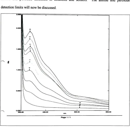
cuvettes.3.4.2 Influence ofHydrogen Peroxide Concentration
The
nextstep
of experimentationincluded making
solutionsthat
contain1M
aniline and
2 M
hydrogen
peroxidein 25
mL of acetonitrile.One
solutioncontained100
mg CNT
and one control solution withoutCNT.
These
solutions were stirred at roomtemperature
for
three
hours.
The
solution withoutCNT
became
alight
yellowcolor andthe
solution withCNT
became
adark
red color at the end ofthe three
hours.
The
solutions were
then
analyzedby
GC/MS
andit
wasdetermined
thataniline, acetonitrile,
carbon
dioxide,
nitrobenzeneandnitrosobenzenewerepresentin both
samples;
however,
the
solutionwithCNT
producedboth
more nitrobenzene and more nitrosobenzenethan
the
solutionwithoutCNT
whencomparing
peakareas.Solutions containing 1 M
anilineand
3 M hydrogen
peroxide werethen
madein 25
mLacetonitrile,
onecontaining 100
mg
ofCNT
and onewithout.The
solution withoutCNT
againturned
alight
yellow colorFigure


Related documents
Product Name: PT Radiant Utama Interinsco Tbk Company Profile - Business Description, Strategies and SWOT Analysis. Web
It was previously reported that high milk yield (11,443 kg fat and protein-corrected milk in preceding 305 d lactation) and associated assumed large energy deficits ( − 82 MJ in
Quantification and localization of contrast agents using delta relaxation enhanced magnetic resonance at 1.5 T. Magn Reson Mater Physics, Biol
RABORAL V‑RG ® is an oral rabies vaccine bait that contains an attenuated (“modified‑live”) recombinant vaccinia virus vector vaccine expressing the rabies virus glycoprotein
Parameter identification based on lag synchronization via hybrid feedback control in uncertain drive response dynamical networks Liu et al Advances in Difference Equations (2017) 2017
The present work demonstrated an efficient strategy of exploiting wheat DDGS as raw material for polymer (poly-D-lactic acid, PDLA) production. The process
In Europe only the species belonging to the genus Rickettsia are responsible for Rickettsiosis, and typically fall into two general groups: the spotted fever group
APHL: Association of Public Health Laboratories; CDC: US Centers for Disease Control and Prevention; CRHRL: Central Public Health Reference Laboratory; DHMT: District Health
