University of Southampton Research Repository
ePrints Soton
Copyright © and Moral Rights for this thesis are retained by the author and/or other copyright owners. A copy can be downloaded for personal non-commercial
research or study, without prior permission or charge. This thesis cannot be
reproduced or quoted extensively from without first obtaining permission in writing from the copyright holder/s. The content must not be changed in any way or sold commercially in any format or medium without the formal permission of the
copyright holders.
When referring to this work, full bibliographic details including the author, title, awarding institution and date of the thesis must be given e.g.
AUTHOR (year of submission) "Full thesis title", University of Southampton, name of the University School or Department, PhD Thesis, pagination
FACULTY OF ENGINEERING, SCIENCE AND
MATHEMATICS
SCHOOL OF ENGINEERING SCIENCES
MATERIALS RESEARCH GROUP
MICROSTRUCTURAL MODELLING OF
FATIGUE IN LAYERED BEARING
ARCHITECTURES
BY
Muhammad Sarfraz Ali
Thesis for the degree of Doctor of Philosophy
UNIVERSITY OF SOUTHAMPTON
ABSTRACT
FACULTY OF ENGINEERING, SCIENCE & MATHEMATICS
SCHOOL OF ENGINEERING SCIENCE
MATERIALS RESEARCH GROUP
Doctor of Philosophy
MICROSTRUCTURAL MODELLING OF FATIGUE IN
LAYERED BEARING ARCHITECTURES
BY
Muhammad Sarfraz Ali
Small automotive plain engine bearings are used to provide the relative motion between the engine block and the crankshaft via the connecting rod. Under rapidly changing engine loads, these bearings may suffer fatigue damage during service. In modern multilayered bearing designs, fatigue resistance is a complex function of engine loading coupled with the layer architecture and a multiphase lining alloy. This research has mostly focussed upon micro-scale fatigue damage initiation on thin (0.2-0.3mm thickness) lining surface and its subsequent growth leading towards gross failure. The systems examined comprise Al alloys and sintered bronze as relatively soft and conformable lining layers. The weight percent composition of Al
lining alloy was Al-6.5Sn-2.5Si-1Cu-1Ni-0.25Mn roll bonded to a stiffer and thicker backing steel layer (1.5-1.8mm thick) via an even thinner Al foil (0.04mm) as an interlayer. The other system comprised an Al lining (Al-20Sn–1Cu) alloy spray coated on to a medium carbon steel layer in the form of a flat bar. All these systems were compared with the previously investigated
Al based designs with lining compositions: Al-12Sn-4Si-1Cu and Al-20Sn-1Cu-0.25Mn
In the previous research, the coarser Si particles in the Al-12Sn-4Si-1Cu lining and
Sn particles in the Al-20Sn-1Cu-0.25Mn alloys were identified as potential crack initiation sites, though the relationship between particle geometry and arrangement/clustering was found to be important. The newly developed Al-6.5Sn-2.5Si-1Cu-1Ni-0.25Mn lining alloy with finer and fewer Sn and Si particles showed a delayed initiation of short fatigue cracks compared to the previous systems. However, a large number of widely scattered intermetallics in the new linings were observed to fracture causing early fatigue initiation at the micro-scale level with some more complex processes of detaching Sn layers from harder intermetallics and Si particles. Using the mechanical property data for bulk lining and secondary phase particles obtained from tensile testing and instrumented hardness testing, stress fields were investigated within the hard particles (intermetallics), surrounding thin layers and the matrix on the basis of the analytical and numerical modelling. On the basis of these modelling results, optimum particle shapes were defined to minimize tensile stresses (within the particles) and hydrostatic stresses (at the particle matrix interfaces). The experimental growth data of a dominant crack when combined with a
Hobson type growth model based upon measured particle distributions and experimental crack growth rates, helped in predicting fatigue life of a similar component at different stress levels. Surface crack driving force reduces considerably when subsurface crack deflection occurred within softer Al interlayer. Replacing this interlayer with a harder brazed sheet did not give any significant difference in the observed fatigue life. In the HVOF systems, crack initiation was observed to be from the weaker interface between a harder matrix and softer circular unmelts as well as from various scattered pores. The overall fatigue life of the HVOF systems was comparable to the previous roll bonded systems; however subsurface deflection of crack at the lining-backing interface resulted in the debonding of the lining and hence the observed lining fatigue resistance may not be a good indication of the overall performance in a bearing system.
At similar lining surface plastic strain levels, the bronze bearing with very thin Sn
and Ni as overlay layers (~7 microns each) showed comparable fatigue resistance to the currently investigated RB Al based designs. However annealing this system resulted in the formation of hard Ni3Sn intermetallics at the Sn-Ni interface, and the observed fatigue resistance of this system was higher than the RB systems. This has been linked to very fine scale local crack deflection in the overlay layers (although these have not been observed clearly).
DECLARATION OF AUTHORSHIP
I, _Muhammad Sarfraz Ali, declare that the thesis entitled _Microstructural
modelling of fatigue in layered bearing architecture and the work presented in the thesis are
both my own and have been generated by me as the result of my own original research. I
confirm that:
• this work was done wholly or mainly while in candidature for a research degree at this
University;
• where I have consulted the published work of others, this is always clearly attributed;
• where I have quoted from the work of others, the source is always given. With the
exception of such quotations, this thesis is entirely my own work;
• I have acknowledged all main sources of help;
• where the thesis is based on work done by myself jointly with others, I have made clear
exactly what was done by others and what I have contributed myself;
• parts of this work have been published as journal/conference proceedings:
• M.C. Mwanza1, M.S. Ali1, S. Syngellakis1, C. Perrin2 and P.A.S. Reed1, Fatigue evaluation of novel HVOF spray coated Al bearing alloys, Al alloy conference ICAA9,
(2004), Australia.
• M.S.Ali1, P.A.S. Reed1, S.Syngellakis2, A comparison of fatigue performance of conventional roll bonded and HVOF spray coated Al bearing alloys, 9th international Fatigue Congress (2006), Atlanta, USA.
• M.S. Ali1, a, P.A.S. Reed1, b, S. Syngellakis2,c, Carl Perrin3,d, Microstructural factors affecting fatigue initiation in various Al based bearing alloys, Mat. Sc. Forum, Vol
519-521 (2006), pp1071-1076
Signed: Muhammad Sarfraz Ali
Acknowledgement
The completion of this research was not possible without the support of a number of people
from Materials Research Group; however, my supervisors Professor Philippa Reed and Dr.
Stavrous Syngellakis made the most important contribution in this regard. I am extremely
grateful for their dedicated supervision, constant encouragement and helpful discussions during
the course of this work.
I would like to acknowledge the financial and materials support of Dana Glacier Vandervell
Bearings, UK and School of Engineering Sciences, University of Southampton, UK. Dr. Carl
Perrin (Director R & D DGV) deserves special gratitude for his participation in technical
discussions and providing necessary data.
I am also grateful to Dr. Mathew Mwanza for his assistance during initial experimental work
and providing me some of his experimental data.
I would like to acknowledge Dr Sunchai Wang and my colleague Andrew Moffat for their
assistance in using some equipment.
I also acknowledge the support of technical and clerical staff; Dave Beckett, Eric Bonner, Bob
Barnes and Gwyneth Skiller. Apart from that, I am also equally grateful to all other colleagues
who provided me an amiable environment for the successful completion of this research.
At last but not least, I am grateful to my parents (Shamim Akhtar and M. Ali), siblings and my
wife Dr. Saima for their constant support and encouragement.
LIST OF SYMBOLS
A Area
Af Area fraction
a Half the length of a crack (µm)
c Subsurface length of crack (µ m)
C Paris constant
dCTOD Crack tip opening displacement
D Deflected length
dmean Mean neighbour distance
E Elastic modulus (MPa)
Hn Nano-hardness number (GPa)
K Stress intensity factor (MPa (m)1/2)
Keff Effective stress intensity factor
N Number of cycles
Nf Number of cycles to failure
Ni Crack initiation life
P Load (in Kgs or Newtons)
ra Aspect ratio
UTS Ultimate tensile strength (MPa)
Vf Volume fraction
σe Engineering stress (MPa)
σtrue True stress (MPa)
σy Yield stress (MPa)
σ0.2 0.2% proof stress (MPa)
σmax Maximum tensile stress at the lining surface (MPa)
σgrad Stress gradient (MPa/mm)
σh Hydrostatic pressure
σt Tensile stress
εe Engineering strain
εtrue True strain
εt Total strain at the lining surface
εs Plastic shear strain intensity
∆εp Plastic strain range
∆K Stress intensity factor
LIST OF ACRONYMS
BEI Back scattered electron image
EBSD Electron back scattered diffraction
EDX Energy dispersive X-rays
FBT Finite body tessellation
FEA Finite element analysis
FEG SEM Field emission gun SEM
HCF High cycle fatigue
HVOF High velocity oxy-fuel
LEFM Linear elastic fracture mechanics
L.A.F Local area fraction
LCF Low cycle fatigue
MSC Microstructurally short fatigue cracks
OM Optical microscopy
PSB Persistent slip bands
PSC Physically short fatigue cracks
RB Roll bonding
SEI Secondary electron image
SEM Scanning electron microscope/microscopy
TABLE OF CONTENTS
1 INTRODUCTION... 1
1.1. BACKGROUND... 1
1.2. OBJECTIVES... 2
1.3. THESIS STRUCTURE... 3
2 LITERATURE REVIEW ... 7
2.1. BEARING MATERIALS... 7
2.1.1. Historical evolution of bearing materials... 7
2.1.2. Bearing materials properties ... 8
2.1.3. Al bearing alloys ... 10
2.1.4. Bronze bearings ... 13
2.1.5. Manufacturing processes... 13
2.1.6. Summary of materials... 15
2.2. FATIGUE OF MATERIALS... 16
2.2.1. Basic definitions... 16
2.2.2. Nucleation and growth of fatigue cracks in ductile materials... 17
2.2.3. Total fatigue life approaches ... 19
2.2.4. Damage tolerant approach to fatigue... 22
2.2.5. Short fatigue cracks... 30
2.2.6. Short crack growth modelling... 34
2.2.7. Fatigue crack deflection ... 36
2.2.8. Effect of external environment on crack growth behaviour ... 38
2.2.9. Summary of fatigue literature ... 40
2.3. TECHNICAL ASPECTS OF ENGINE BEARINGS... 40
2.3.1. Load Cycles in plain bearings... 41
2.3.2. Fatigue behaviour of engine bearings... 42
2.3.3. Summary of bearings fatigue literature ... 45
3 MATERIALS AND EXPERIMENTAL TECHNIQUES... 66
3.1. MATERIALS... 66
3.2. MANUFACTURING PROCESSES... 68
3.2.1. Roll bonding process... 68
3.2.2. Manufacture of Bronze bearing ... 68
3.3. MATERIALS CHARACTERIZATION... 70
3.3.1. Microstructural characterization ... 70
3.3.2. Mechanical testing ... 75
3.3.3. Fatigue test ... 78
3.3.4. Measurement of total strain at the lining surface... 81
4 MATERIALS CHARACTERIZATION ... 96
4.1. MICROSTRUCTURAL AND COMPOSITIONAL ANALYSIS... 96
4.1.1. Microstructural view of the layered architecture of different systems... 96
4.1.2. Detailed microstructural and compositional analysis of Al-based systems ... 98
4.1.3. Detailed microstructural analysis of Cu based bearing systems... 108
4.1.4. Discussion-microstructural characterization results ... 111
4.2. MECHANICAL PROPERTIES... 115
4.2.1. Bulk mechanical properties ... 115
4.2.2. Nano-hardness indentation... 118
4.2.3. Discussion-mechanical properties ... 122
4.3. SUMMARY... 126
5 FATIGUE TEST RESULTS AND POST FAILURE ANALYSIS... 154
5.1. STRESSES AND STRAINS DEVELOPED IN A 3-POINT BEND TEST... 154
5.1.1. Basic assumptions of the FE model... 155
5.1.2. Layer thickness sensitivity study ... 156
5.1.3. Effect of layer mechanical properties... 158
5.1.4. Summary of the sensitivity analysis... 161
5.1.5. Experimental validation of FE strain predictions ... 162
5.1.6. Estimation of correct surface plastic strains... 166
5.1.7. Summary of the strain analysis results ... 166
5.2. FATIGUE TEST RESULTS... 167
5.2.1. Lifetime results... 167
5.2.2. Effect of specimen geometry on fatigue life ... 172
5.2.3. Behaviour of short fatigue cracks ... 172
5.2.4. Short crack initiation... 173
5.2.5. Short crack propagation behaviour... 175
5.3. SUBSURFACE CRACK GROWTH IN THE LAYERED SYSTEMS... 180
5.4. SUMMARY OF THE RESULTS... 181
6 FURTHER ANALYSIS AND DISCUSSION ... 215
6.1. MICROSTRUCTURAL FATIGUE DAMAGE INITIATION... 215
6.1.2. Particles observed in the AS20S lining... 216
6.2. MICROMECHANICAL STUDY OF INITIATION... 219
6.2.1. Analytical approach ... 220
6.2.2. Numerical Modelling... 222
6.2.3. Optimum geometry for maximum fatigue resistance ... 228
6.3. SURFACE SHORT CRACK GROWTH BEHAVIOUR... 229
6.3.1. Crack tip characterization ... 229
6.3.2. Plastic zone calculation, crack coalescence and shielding... 230
6.3.3. Crack growth modelling and fatigue life prediction... 232
6.4. SUBSURFACE CRACK GROWTH... 239
6.4.1. Effect of interlayer... 239
6.5. PERFORMANCE OF RB AND HVOF SYSTEMS... 240
6.6. BRONZE BEARINGS... 241
7 SUMMARY, CONCLUSIONS AND FUTURE WORK ... 269
7.1. SUMMARY OF KEY RESULTS AND CONCLUSIONS... 269
7.1.1. Microstructural and mechanical characteristics ... 269
7.1.2. Microscale fatigue damage initiation and growth... 270
7.1.3. Layer architecture... 271
7.1.4. Fatigue life... 271
7.1.5. Bearing tests for in-service performance... 272
7.2. FUTURE WORK... 273
7.2.1. Experimental work ... 273
LIST OF TABLES
Table 3.1: Materials and geometrical thicknesses of various layers used in different multilayered systems investigated during current and previous research. The thickness values highlighted are those related
to the flat bar specimens. ... 67
Table 3.2 Grinding and polishing routes adopted for different systems. ... 72
Table 4.1: Composition of different materials measured via EDX analysis... 101
Table 4.2: Compositional results of brazed sheet. ... 102
Table 4.3: Average grain size and orientation results for Al obtained via EBSD ... 103
Table 4.4: Result of the FBT analysis of AS20S lining surface ... 106
Table 4.5: Estimation of % age Volume fraction based upon FBT analysis... 107
Table 4.6: EDX compositional results for the RB168 systems... 111
Table 4.7: Comparison of various features of different particles measured by FBT for current and previous lining alloys. ... 113
Table 4.8: Tensile test results for different materials. Data for AS1241 and AS16 systems was obtained from previous work... 116
Table 4.9: Microhardness test results for various materials measured at a load of 50g... 118
Table 4.10: Nano-indentation test results. The unit of all measured values are GPa ... 121
Table 4.11: Nanohardness results for various particles. The unit of all measured values are GPa... 122
Table 5.1: Test matrix for the layer mechanical properties sensitivity analysis ... 160
Table 5.2: Effect of changing mechanical properties of different layers on the maximum lining surface stress and strain. A negative sign indicates a decrease in the quantity. ... 161
Table 5.3: Fatigue lifetime test results of multilayered bearings... 170
Table 5.4: Fatigue lifetime test results of multilayered flat bars... 171
Table 5.5: Measured values of crack tip tortuosity ... 180
Table 6.1: FBT measured feature for various short crack initiating particles in the AS20S lining (number of particles in brackets)... 218
Figure 1.1: A view of 4 stroke car engine (After1) showing the location of plain bearings. ... 5
Figure 1.2: (a) Connecting rod-crank shaft assembly. (b) Hydrodynamic stress concentrations along the lining of bearing (courtesy DGV)... 5
Figure 1.3: A multilayered bearing system showing various layers in an Al based bearing design... 6
Figure 2.1. (a) Al-Si phase diagram (b) Al-Cu phase diagram (After8). ... 52
Figure 2.2: Microstructure of (a) Al-0.5Si-1Cu (b) Al-1.5Si-0.5Cu. Si and globular CuAl2 is denoted by 5 and Al( ) is denoted by 1. These are modified with 0.002%Sr. (After Garcia7)... 53
Figure 2.3: (a) Al–7Si–0.5Ni and (b) Al–7Si–1.0Ni both of them modified. α (Al) solid solution is denoted by 1, globular-fibrous Si of the eutectic phase is marked with 2, and NiAl3 block particles are denoted by 4 (After Garcia7). ... 53
Figure 2.4: Al-Sn phase diagram (After Braithwaite2). ... 54
Figure 2.5: The unfolded ternary diagram and projection of liquid phases face for Al–Sn–Si system. (After Yuan12). ... 54
Figure 2.6: SEM morphology of Al–10Sn–4Si-0.8Cu alloy after homogenization (a) back-scattering electronic image (b) secondary electronic image (After Yuan12). ... 55
Figure 2.7: Fatigue crack initiation sites: fracture of brittle Al7Cu2Fe intermetallic (Optical micrograph) in 7010 alloy (After9). ... 55
Figure 2.8:(a) Binary phase diagram of Cu-Sn systems (b) ternary diagram of Cu-Sn-Ni systems (After14).. 56
Figure 2.9: (a) A schematic of commercially adopted roll bonding processes for Al and Cu based bearings (b). A modelled spray coating gun used for HVOF process (After18)... 57
Figure 2.10: (a) Schematic of hysteresis loop developed during cyclic deformation. (b) Cyclic stress strain curve obtained from hysteresis loops (After22). ... 58
Figure 2.11: Persistent slip bands in cycled polycrystalline Cu (After22). ... 58
Figure 2.12:Development of a crack along slip planes (After Benham34). ... 59
Figure 2.13: (a) Intrusions and (b) extrusions on Cu surface fatigued at -183oC (After60). ... 59
Figure 2.14: (a) Effect of mean stress on fatigue life. (b) Constant life curves for fatigue loading. ... 60
Figure 2.15: An elliptical crack in an infinite slab under far field applied stress (After Suresh60)... 60
Figure 2.16: Crack opening modes (mode I-tensile opening, mode II, in-plane sliding, mode III anti-plane shear (After60). ... 61
Figure 2.17: Components of stress in the crack tip stress field. (After Suresh60)... 61
Figure 2.18: Stress distribution at a crack tip due to local yielding (After Benham34). ... 62
Figure 2.19: Different regimes of stable fatigue crack growth (After Suresh60). ... 62
Figure 2.20: A schematic illustration of the plasticity induced crack closure... 63
Figure 2.21: Difference between growth behaviour of short and long fatigue cracks (After). ... 63
Figure 2.23: Schematic of fatigue crack initiation near a free surface by the synergistic effect of single slip and environmental effect60... 64 Figure 2.24: Development of pressures during hydrodynamic action ... 65 Figure 2.25: Schematic diagram showing different operating regimes for a journal bearing with fluid film
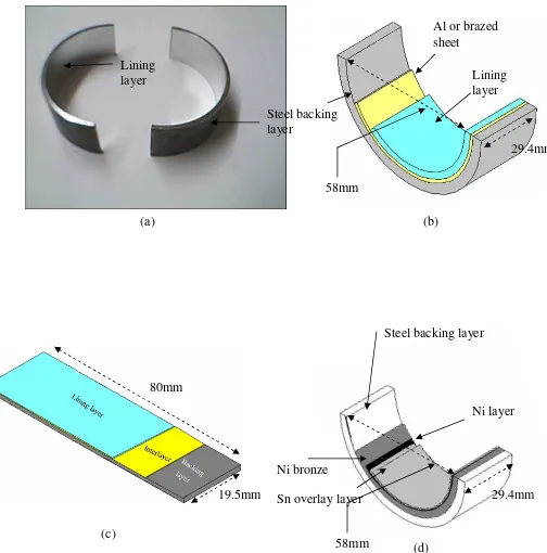
lubrication ((After) ... 65 Figure 3.1: (a) A view of the actual finished bearings. (b) Schematic of half shell AS20S/AS20 bearing. (c)
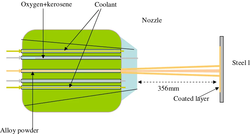
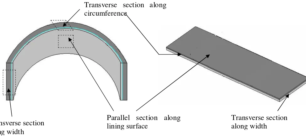
Flat bar specimen of AS20S/AS20 systems (d) RB168 bearing showing different layers. ... 84 Figure 3.2:A schematic of the RB process for manufacture of Al alloy plain bearing half shells... 85 Figure 3.3: A schematic of manufacturing of bimetal strip used for the bronze bearing (courtesy DGV) ... 86 Figure 3.4:A schematic of the HVOF spray coating process used for coating Al alloy lining on flat steel strips (After4). ... 86 Figure 3.5: Specimen sectioning method for finished bearing and flat bar specimens to be used for
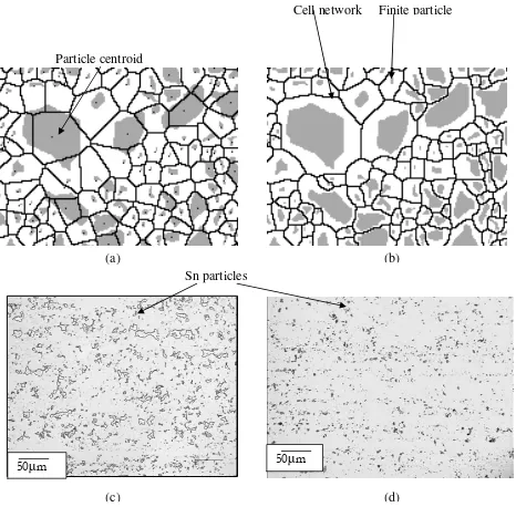
metallography. ... 87 Figure 3.6: (a) A Dirichlet tessellated image. (b) An FBT image (c) Optical image of AS16 lining material (d) Optical image of AS20S lining material... 88 Figure 3.7:.Feature measurements obtained by FBT (After Joyce13) ... 89 Figure 3.8: Methodology of microhardness indentation (a) Constant load micro-indentation. (b) Variable
load micro-indentation within layers... 90 Figure 3.9: A schematic of (a) nanohardness-tester (After Micromaterials) (b) loading/unloading process of
the indenter. ... 91 Figure 3.10: A schematic of the loading and unloading curve obtained from one load cycle during
Nanoindentation... 92 Figure 3.11: Tensile test specimen geometry (a) Monolithic lining and interlayers (b) Steel layer ... 92 Figure 3.12: A schematic of accelerated rig test used for fatigue testing of bearings adopted by DGV
(Courtesy DGV). ... 93 Figure 3.13. Three point bend fatigue test configuration for (a) bearings and (b) flat bars. ... 94 Figure 3.14:Strain gauge attachment to the top lining surface of (a) flat bars and (b) finished bearings... 95 Figure 4.1: Schematics of various surfaces of (a) bearing (b) flat bar specimens subjected to microstructural
analysis... 128 Figure 4.2: Three dimensional optical micrographs of Al based systems: (a) AS20S bearing (b) AS20 bearing (c) monolithic brazed sheet and (d) HVOF specimens. ... 129 Figure 4.3: Three dimensional optical micrographs of Cu based bearing systems (a) RB168 non-heat treated (b) RB168 heat treated bearing specimens (c) An optical image of the HT specimen showing top layers. ... 130 Figure 4.4: AS20S lining (a) SEM image of AS20S/AS20 bearing lining (b) AS20S lining showing as cast
Figure 4.5: (a-c) Results of the EDX smart area mapping of AS20 bearing interlayer. The white regions in each image shows abundance of the element mentioned below the image. (d) BEI image of the original
monolithic brazed sheet. ... 132
Figure 4.6: Backing steel layers of the (a) AS20S and (b) AS20 systems... 133
Figure 4.7: Microstructure of the HVOF lining (a) BEI image of the lining surface (b) TEM image after .. 133
Figure 4.8:(a) BEI image of the interface between the lining and the backing steel layer (b) Optical image of the backing steel layer of the HVOF system... 134
Figure 4.9: EBSD map of the Al matrix of the LW plane of RB systems linings (a) AS20S (b) AS20 (c) AS16 (d) AS1241 systems. ... 135
Figure 4.10: Distribution of grain size in the LW plane of the lining surface of (a) AS20S (b) AS20 (c) AS16 (d) AS1241 bearings... 136
Figure 4.11: Distribution of misorientation angle in the LW plane of the lining surface of (a) AS16 (b) AS1241 (c) AS20S (d) AS20 bearings... 137
Figure 4.12: Finite body tessellation analysis for AS20S lining: (a) SEI (b) BEI image of lining surface. Binary images showing (c) Sn and (d) intermetallic particles. ... 138
Figure 4.13: Histogram of Sn,Si and Intermetallics showing (a) object area (b) cell area... 139
Figure 4.14: Histogram of Sn, Si and Intermetallics showing (a) object aspect ratio (b) cell aspect ratio. ... 140
Figure 4.15: Histogram of Sn, Si and Intermetallics showing (a) object angle (b) cell angle... 141
Figure 4.16: Histogram of Sn, Si and Intermetallics showing (a) L.A.F (b) No of Nearest neighbours... 142
Figure 4.17: Histogram of Sn and Intermetallics showing Mean Near Neighbour Distance. ... 143
Figure 4.18: FBT analysis of unmelt region in the HVOF surface (a) original image (b) binary images... 144
Figure 4.19: Distribution of FBT measured (a) object area (b) object AR and (c) mean near neighbour distance for the circular unmelts observed in the HVOF lining... 145
Figure 4.20: SEI images of (a) heat treated and (b) as plated RB168 bearing cross-section showing Ni and Sn overlay layers electroplated on the surface of Cu-Sn-Ni lining layer... 146
Figure 4.21: Microstructure of the cross-section of RB168 bearing specimen heat treated at different times and temperatures. ... 146
Figure 4.22: Growth behaviour of Ni-Sn interfacial compound layer at 190 and 200Co... 147
Figure 4.23 (a) Binary phase diagram of Cu-Sn systems (b) ternary diagram of Cu-Sn-Ni systems (After). 147 Figure 4.24: RB168 bearing lining etched surface showing Cu grains of (a) heat treated specimen (b) non-heat treated specimen ... 148
Figure 4.25: Optical micrographs of the lining surfaces of the (a) AS1241 and (b) AS20S bearings. ... 148
Figure 4.26: True stress vs. true strain curves for the monolithic layers of different systems. Data for the AS1241, AS16 systems and cast Sn was obtained from the previous work4... 149
Figure 4.27: Load vs. indent diagonal data for various layers of different systems. Data for AS1241 and AS16 was obtained form previous work4. ... 150
Figure 4.29: Some targeted secondary phase particles during nano-indentation (a) AS20S lining (b) HVOF lining (c) RB168 overlay layers... 152 Figure 4.30: A schematic of secondary phase region being targeted by nano-indenter in (a) AS20S lining (b)
RB168 interfacial layers between Sn and Ni overlay layers. ... 153 Figure 5.1: FE simulated stress strain profiles through different layers developed under three point static
bend test for the AS20S (a) bearing tensile stresses (b) bearing plastic strains (c) flat bar tensile stresses (d) flat bar plastic strains... 184 Figure 5.2: Effect of lining layer thickness on maximum lining surface tensile stress and plastic strain for (a) bearing and (b) flat bar specimen. AS20S monolithic lining, Al and AS20S flat bar steel elasto-plastic properties have been used for lining, inter (0.04mm thick) and backing layers (1.5mm thick)
respectively... 185 Figure 5.3: Effect of backing layer thickness on maximum lining surface tensile stress and plastic strain for
(a) bearing and (b) flat bar specimen. AS20S lining, Al foil and AS20S flat bar steel elasto-plastic properties have been used for lining (0.3mm thick), inter (0.04mm) and backing layers respectively. 186 Figure 5.4: Effect of variation of lining layer tensile properties on the lining surface stresses and plastic
strains for (a) bearing (b) flat bar specimens. AS20S flat bar steel (1.5mm thick) and Al foil (0.04mm thick) were used as backing and interlayers respectively (lining = 0.2mm thick)... 187 Figure 5.5: Effect of variation of backing layer tensile properties on the lining surface stresses and strains for
(a) bearing (b) flat bar specimens. AS20S monolithic lining (0.2mm thick) and Al foil (0.04mm thick) were used as lining and interlayers respectively (backing =1.5mm thick). ... 188 Figure 5.6: Effect of varying (a) lining σ0.2% (AS20S steel as backing layer) and (b) steel backing E (AS20S
monolithic as lining layer) upon lining surface stresses and strains. Thicknesses of lining, inter (Al foil) and backing layer are 0.2, 0.04 and 1.5mm respectively. ... 189 Figure 5.7: Load vs. total strain curves for flat bars/strips (a) current flat bar systems (b) previous flat bar
systems. ... 190 Figure 5.8: (a) Geometrical representation of the possible sliding of the roller during the lining strain
measurement experiment. (b) Cracks developed in the vicinity of the attached strain gauge on the lining surface of the HVOF flat bar specimen... 191 Figure 5.9. (a) Experimental total strain data vs. FE predicted total strain data for flat bar (b)
Experimentally predicted vs. corrected values of the maximum lining total strains. ... 192 Figure 5.10: Load vs. experimental and FE based total strain data for all previous and current bearings. . 193 Figure 5.11: Bearing end in the specimen jig during three point load (a) FE based bearing model showing
fully constrained end... 193 Figure 5.12:(a) Experimental vs. FE predicted total strain values for bearing systems (b) Load vs.
experimental and corrected values of maximum lining surface total strains... 194 Figure 5.13: Comparison of the FE predicted and corrected values of max lining εp for (a) finished bearings
Figure 5.14: (a) Loading roller-bearing contact area at the backing layer of the bearing (b) Fatigue life of AS20S and AS20 bearing specimens in the form of S-N and Pav –N compared with the fatigue data from accelerated rig test. ... 196 Figure 5.15: Fatigue life of all current and previous bearing specimens in the form of εp-N under ambient
and engine oil environment. Plastic strain amplitude values are FE based validated by experimental strain results... 197 Figure 5.16: Fatigue life of all previous and new Al based flat bar specimens compared with the spray coated
flat bar specimens in the form of εp/2-N. Data for the AS1241 and AS16 some of the HVOF systems
was obtained from previous research. ... 198 Figure 5.17: A comparison of fatigue lifetime results for the RB168 and AS20S bearing systems in air. Plastic
strains amplitude values were based upon elastoplastic FE model validated through the experimental strain measurement at the bearing lining surface. ... 198 Figure 5.18: A comparison of fatigue life of RB bearing and flat bar specimens. All data for the AS16 and
AS1241 was obtained from previous research... 199 Figure 5.19. Method of defining a two dimensional coordinates systems on the flat bar lining surface to study the crack fields. ... 200 Figure 5.20: Optical micrograph of the surface replicas of (a) AS20S (b) AS20. BEI images (c) AS20S (d)
AS20 lining surface (e) BEI image from larger area of AS20S lining surface. ... 201 Figure 5.21: (a) Optical image of the replica from HVOF flat bar (b) BEI and (d) SEI images of crack
initiating from unmelt. (c) Crack initiating from pores surrounding unmelts. ... 202 Figure 5.22: Lining surface crack growth behaviour. Optical images of surface replicas of (a) AS20S (b)
AS20 (c) HVOF lining at different life time intervals. Typical crack shown by red marks... 203 Figure 5.23: Lining surface crack growth behaviour of AS20S, AS20 and HVOF flat bar systems at a
constant maximum εp of 0.0064±0.003. da/dN vs. Crack length data was produced from optical images
of the lining surface replicas during interrupted fatigue tests. ... 204 Figure 5.24: Optical micrograph of the HVOF replica showing instant emergence of very long cracks. ... 204 Figure 5.25 (a) Crack geometry used for short crack ∆K calculations from Scott and Thorpe equation (b)
Increase in a/c value with coalescence of cracks... 205 Figure 5.26:(a) da/dN vs ∆K of various cracks in the high strain region of the flat bar specimens of all three
systems (b) A geometrical representation of subsurface retardation of crack due to a harder backing layer... 206 Figure 5.27: (a) Variation of da/dN surface cracks at different locations of (a) AS20S and (b) HVOF lining
Figure 5.32: Surface morphology of cracks in RB168 (a and b) non-heat treated (c and d) heat treated specimen... 212 Figure 5.33: Micrographs showing subsurface penetration of fatigue cracks in (a) AS20S ... 213 Figure 5.34: Subsurface crack trajectory in the RB168 (a) heat treated (b) non-heat treated specimen. (c)
Crack penetrating into the steel backing. Both specimens tested at maximum estimated lining plastic strain of 0.003... 214 Figure 6.1: (a) A comparison of fatigue initiation and growth lifetimes of different systems. Fatigue initiation in (b & c) AS20S (d) AS1241 and (e) AS16 lining5... 244 Figure 6.2: FBT measured (a) object area (b) aspect ratio of short crack initiating particles... 245 Figure 6.3: FBT measured (a) object angle (b) and dmean of short crack initiating particles. ... 246
Figure 6.4: A schematic of the geometry of (a) bi-material model used in analytical and numerical modelling (b) elasto-plastic tri-material model used for numerical modelling. ... 247 Figure 6.5:Variation of particle and matrix stresses calculated by Eshelby analysis for the bimaterial model
used for (a)AS20S lining and (b) for HVOF lining with the particle ra... 248 Figure 6.6: A 2-D meshed geometrtrical model of (a) a simple intermetallic and (b) a layered intermetallic
particle embedded in Al matrix. ... 249 Figure 6.7: FE predicted (a) tensile and (b) hydrostatic stresses in a bimaterial linear elastic model for the
AS20S type lining... 250 Figure 6.8: FE and Eshelby predictions of maximum tensile stresses in a bimaterial linear elastic model... 250 Figure 6.9: General σ-ε behaviour of all layers used. Data for AS1241, AS16 systems and Sn was obtained
from previous work at Southampton... 251 Figure 6.10: Effect of variation of elastic modulus of the embedded intermetallic particle on the resultant σ-ε
in the intermetallic particle and the matrix of AS20S lining simulated by elastoplastic bimaterial FE model... 252 Figure 6.11: Effect of variation of volume fraction of the embedded intermetallic particle on the resultant σ-ε
in the intermetallic particle and the matrix of AS20S lining simulated by elastoplastic bimaterial FE model... 252 Figure 6.12: Disribution of (a) tensile stress (b) hydrostatic stress and (c) plastic shear strain in a tri-material
FE model representing hard intermetallic encapsulated within soft Sn layer and embedded in Al core. ... 253 Figure 6.13: Variation of critical (a) stresses and (b) plastic shear strains with the change in Sn layer
thickness around intermetallic particle. ... 254 Figure 6.14: Variation of critical (a) stresses and (b) plastic shear strains with the change in orientation of
intermetallic particle... 255 Figure 6.15: Variation of (a) tensile stresses (b) hydrostatic stress (c) plastic shear strain as a function of
particle (intermetallic) orientation (θ) and Sn layer thickness at ra=3. ... 256
Figure 6.17: Variation of (a) tensile stresses (b) hydrostatic stress (c) plastic shear strain as a function of
particle (intermetallic) ra and Sn layer thickness. ... 258
Figure 6.18: Schematic of the crack interaction definitions approach used by Joyce10. ... 259
Figure 6.19 Short fatigue crack interactions at different life time fractions for AS20S lining. ... 260
Figure 6.20: Short fatigue crack interactions at different life time fractions for AS20 lining. ... 261
Figure 6.21: Short fatigue crack interactions at different life time fractions for HVOF lining... 263
Figure 6.22: (a) A scaled schematic view of the AS20S flat bar lining loading span.(b) a magnified view of the central narrow width where microstructurally observed particle distribution is shown on the basis of FBT measured dm... 263
Figure 6.23: Experimentally measured and fitted upper and lower bounds of the crack growth curves. .... 264
Figure 6.24: A schematic of assumed crack growth behaviour to a surface length of 5mm indicating the implementation of upper and lower growth bounds. ... 265
Figure 6.25: Fatigue life of AS20S flat bar specimens measured experimentally compared to the estimated life time data... 265
Figure 6.26: (a) A comparison of fatigue initiation life of the AS20S flat bars at different plastic strain amplitudes. (b) A comparison of the fatigue initiation life of the AS20S flat bar with the previous RB systems at the same plastic strain levels. ... 267
Plain automotive journal bearings form an important part of the internal combustion
engine and may suffer a complex combination of various types of failures under normal engine
operating conditions. The premature causes of failure are fatigue, sliding surface wear and
erosion due to cavitation phenomena. ‘Fatigue failure’ of engine bearings is the subject of this
research. This problem may hamper the life of the component and the continued functioning of
the automotive engine. As engine designs are modified and more stringent performance targets
are set for bearings, there is a growing potential for research in optimizing the fatigue resistance
of such components.
1.1.
Background
Competition between automobile manufacturers in achieving the best engine
performance during the past few decades has resulted in sophisticated designs of automobile
engines, which are lightweight, compact and have high output power. The high specific output
power must be transferred from the piston-connecting rod assembly to the crankshaft via the
plain bearings at the big end of the connecting rod. Location of bearings in a four-stroke car
engine is shown in Figure 1.1. A simplified view of plain bearings present at the connecting rod
big end and crankshaft periphery1 is shown in Figure 1.2 (a). Innovations in the design of automobile engines push bearing manufacturers to search for new bearing materials that can
withstand high output engine power and a more severe engine operating environment (such as
high temperature and hydrodynamic pressures). The advent of new bearing materials,
especially those used as linings has a great impact upon production techniques for bearings. The
latest trend is to optimize the selection criteria of a manufacturing route based upon economic
feasibility and the best possible use of the material’s specific characteristics.
During engine operation, the bearing assembly is usually designed to operate with
hydrodynamic lubrication i.e. the use of separating forces that are generated in a film of oil,
which is dragged by a journal into a diminishing clearance space. These plain bearings consist
of two half shells clamped together within a housing to support the journal. Since the function
of the bearing is to transmit the engine load between the connecting rod and the crank pin while
both have a relative movement with respect to each other, the former should therefore be able to
hydrodynamic action of the lubricating oil present in the form of a thin film between the
surfaces of the plain bearing and the crank pin2. Figure 1.2 (b) shows the schematic of distribution of the hydrodynamic pressure along the lining surface of bearing.
The presence of a hydrodynamic oil layer with high pulsating load levels gives
rise to complex fatigue failure mechanisms. The need for a bearing system that provides good
sliding properties as well as mechanical strength has led to the use of multilayered bearing
architectures. The layer architecture of bearing systems is equally important with regard to the
loads encountered during functioning of the engine and the design integrity. Figure 1.3 shows
the architecture of a modern bearing with different layers. The lining layer is typically a
multiphase alloy in which hard and soft particles are combined to incorporate good tribological
properties such as wear resistance, strength and low coefficient of friction together with good
seizure resistance properties such as conformability. The stiffer and thicker steel backing layer
provides the constraint to the bearing shell. The thin interlayer used in the Al based designs
assures a strong bond between the lining and the backing layer as well as retarding any reaction
of Al and Fe to form brittle intermetallic compounds in the steel3. The layer architecture of bronze bearings is more complex. A relatively harder lining layer (compared to the Al alloy
lining) contributes to wear resistance and overall constraint, whereas a soft and thin Sn layer
together with a harder Ni layer (underneath) used as an overlay provides the specific bearing
lubrication characteristics. Since the main concern of this research is the fatigue performance
evaluation of half shell plain bearings consisting of several layers of different types of materials,
a strong micromechanistic understanding to fatigue failure will be developed on a metallurgical
basis. A precise knowledge of specific microstructural characteristics of a material is essential to
quantify the damage mechanisms under cyclic loading.
Gross fatigue failure of automobile engine bearings during service is far less likely
than smaller scale fatigue damage that occurs at the lining surface giving rise to lining pitting or
local lining decohesion.
1.2.
Objectives
The fundamental objective of this research is to investigate fatigue behaviour of
various multilayered bearing designs as a function of multiphase lining microstructures coupled
with a layer architecture comprising materials of different mechanical properties. The total
initiation and (2) growth of microstructurally short fatigue cracks. The focus of this work,
building on previous research at Southampton, was to understand the micro-scale fatigue
initiation phase and its subsequent growth through complex multilayered bearing designs and to
define the optimum fatigue resistant microstructure and layer design. Specific aims of the
current work could be described as follows:
• Understand the effects of modifications of the microstructure due to compositional or
manufacturing alterations in the bearing-lining alloy.
• Identify the microstructure that is more resistant to fatigue initiation. Using analytical and
numerical modelling, establish micromechanical approaches that may help in defining the
optimum microstructures resistant to fatigue damage initiation.
• Establish approaches to predict the life of similar components at various stress levels.
• Assess the role of subsurface and overlay layers in providing resistance to crack growth and
overall fatigue resistance.
In addition to the major objectives mentioned above, this research also aims to focus
upon the contribution of the mesoscopic properties of different layers used in different
subsystems to the overall fatigue response and hence performance of the system.
1.3.
Thesis structure
After a brief introduction to the current research background and objectives, Chapter
2 comprises the literature review. Section 2.1 introduces bearing materials in general based on
their historical evolution, characteristics required, most common Al and Cu based bearing alloys
used as lining materials and various manufacturing routes. Section 2.2 briefly introduces fatigue
and concepts including the behaviour of materials under cyclic loads, fatigue failure
mechanisms and various appropriate modelling approaches. Section 2.3 describes the fatigue
process in relation to engine bearings and hydrodynamic action occurring during engine
operation.
Chapter 3 describes the materials assessed and the experimental methodology used
to investigate various bearing systems based on their microstructural, mechanical and fatigue
characteristics. Chapter 4 presents a detailed characterization of the various layers in each
system based on their microstructure and local mechanical properties. Chapter 5 (Section 5.1)
starts with a detailed analysis of the stresses and strains developed in the 3-point bend test (used
modelling results validated through experimentally obtained strain gauge results. Section 5.2
describes the fatigue test results based on total life and short crack initiation and growth.
Chapter 6 presents further analysis of the fatigue initiation process with a discussion of the
micromechanical approaches adopted to explain fatigue initiation and growth together with
further discussion on surface growth of short cracks and subsurface penetration. Chapter 7
summarizes the key results and conclusions as well as important areas of future research.
The references for each chapter are given at the end of the chapter followed by
corresponding figures.
1
Lorenz. Ratke, Bearing materials, Homepage research group polyphase solidification, 2(1999)
(www.kp.dlr.de/Erstarrung/web_eng/lager_eng.html)
2
Gyde, N. (1969). PhD. Thesis, Technical university of Denmark, Copenhagen.
3
Braithwaite, E. R.(1967). Lubrications and Lubricants. European. Managegr of Chemical.
Figure 1.1: A view of 4 stroke car engine (After1) showing the location of plain bearings.
Figure 1.2: (a) Connecting rod-crank shaft assembly. (b) Hydrodynamic stress concentrations
along the lining of bearing (courtesy DGV).
Plain
bearings
Journal Connecting
rod
Plain bearing
Crank shaft
[image:25.612.62.566.374.663.2]Figure 1.3: A multilayered bearing system showing various layers in an Al based bearing design. Steel backing
layer
Interlayer
2
LITERATURE REVIEW
The literature review related to this research encompasses three major topics (i)
bearing materials (ii) fatigue failure and (iii) technical aspects of plain engine bearings. These
are followed by various subheadings to explain the classical background and current relevent
research.
2.1.
Bearing materials
This section is concerned with historical evolution of bearing materials,
characteristics required for bearing materials, phases present in different bearing alloys as well
as effect of alloying elements on their mechanical properties and important manufacturing
techniques. The main focus is Al lining alloys; however, a part of this literature is also
dedicated to bronze lining materials.
2.1.1. Historical evolution of bearing materials
Bearings have been in use in the rotating parts of virtually all machines including
automobile engines. The automobile industry is a major user of bearings and all moving parts in
an engine must be supported by some kind of bearing. Since the purpose of the bearing is to
transmit a load through two elements moving relative to each other, the friction characteristics
of the bearing lining material are of immense importance. Development of bearing materials
dates back to the emergence of tribology as a field of research as surface friction and wear
together with conformability were the key aspects fundamental to the selection criterion of
bearings1.
Sn and Pb being soft and easily castable first attracted the attention of bearing
manufacturers in the 19th century. However, their low strength and inability to carry
appreciable loads pushed the manufacturers to search for means of improving their strength
while maintaining their conformable characteristics. This led to the addition of alloying
elements such as Sb and Cu to Sn (Cu and Sb improve strength and corrosion resistance
respectively), which resulted in Babbit metal, the historical bearing alloy2. Since the invention
of Babbitmetal (Sn-11Sb-6Cu) by Isaac Babbit in 1839, further improvements in bearing alloys
metal has now been replaced by Cu-Pb and Al based systems. Cu-Pb alloys were introduced in
1920 and consisted of a two-phase system and had much higher strength than any of the Sn or
Pb based alloys. Recent developments in automobile engines to increase the engine power and
to reduce the fuel consumption, size and weight of engines have added to the total stress to be
carried by the bearings at crankshaft and connecting rods. The Cu-Pb bearing systems therefore
experience wear, corrosion and seizure problems when subjected to these higher stresses, via the
lubricating oil film and high temperature environments (Mihara)3. Hydrodynamic loading action
will be discussed further in Section 2.3. Moreover, Pb being chemically hazardous to human
life, was also considered a risk to the environment.
The requirement to achieve the best bearing properties along with strength, wear
and corrosion resistance resulted in the large scale use of Al-Sn alloys in 1950. The Al alloy
lining is suitable for corrosion resistance, but the cyclic loads that arise during the operation of
the engine may result in early fatigue failure. Modifications in Al alloy compositions have been
made in order to improve their fatigue resistance at higher temperatures4. The addition of
elements such as hard Si and soft Sn improves the antiscoring and antifrictional properties of Al
whilst addition of small amounts of Cu, Ni and Mn improves the strength and hardness of the
bearings.
2.1.2. Bearing materials properties
The efficient and sustained functioning of bearings during the operation of an
engine is sensitive to the design as well as the structural and mechanical characteristics of all the
materials of the bearing system in general and the lining material in particular. The combination
of multilayered bearing systems with the multiphase lining that may come in contact with the
shaft or journal in the presence of hydrodynamic pressures gives rise to conflicting demands
upon the materials properties.
The most important materials properties required by finished bearings are briefly
summarized under the following subheadings2,5:
2.1.2.1.Load carrying properties
The bearing materials must possess enough strength and stiffness to withstand the
load being transmitted between the journal and the housing. The level of strength required
damage due to stresses which arise during operation of the automobile engine. In addition to
these, local load concentrations may arise due to shaft misalignment or vibrations.
2.1.2.1.1 Fatigue resistance: Plain bearings are located at the connecting rod-crank shaft
assembly where they experience cyclic engine-piston loads. Thus bearing lining is subjected to
cyclic loads (acting through hydrodynamic oil layer) which give rise to cyclic stresses varying
in intensity along the lining periphery as well through various layers of a multilayered bearing.
The bearing lining material should be able to withstand these cyclic stresses and resist the
initiation and growth of fatigue cracks that ultimately lead to catastrophic failure.
2.1.2.1.2 Toughness: Toughness of the bulk bearing is an important mechanical property that
resists the accumulation of micro-cracks because the latter may result in catastrophic damage
under cyclic loading. The toughness level in a finished component depends upon the post
fabrication heat treatments.
2.1.2.1.3 Cavitation erosion resistance: Localized reduction in the oil pressure may cause the
formation of bubbles. These bubbles upon further implosion may result in concentrated impact
loading at the bearing surface. The bearing material must have sufficient resistance to bear such
impact loads.
2.1.2.1.4 Shock Resistance: The bearing surface may also come across shock loads while in
operation and must be capable of absorbing them in order to minimize damage to the lining.
2.1.2.2.Wear resistance
Where a strict control of the bearing clearance is required, the dimensional stability of
the system is one of the key issues. During operation of the bearing, the thin oil film may lose
its continuity and direct contact between the mating surfaces may result in severe wear of the
bearing functional surface. While choosing the lining materials for the bearing, the wear
resistance of the material is always one of the most important factors to be considered. Wear of
the bearing lining may result from dirt particles in the lubricant or excessive wear debris. The
ideal bearing lining must have the ability to absorb these contaminants.
2.1.2.2.1 Embeddability: The clearance between the bearing surface and the surface of shaft or
journal may encounter contaminations such as local or foreign particles that may circulate with
the lubricant. These particles must be absorbed by the bearing surface in order to reduce the
2.1.2.3.Miscellaneous properties
2.1.2.3.1 Compatibility: The bearing material must have resistance to welding or joining to its
mating surface under conditions of rubbing and friction.
2.1.2.3.2 Conformability: The bearing is usually in contact with the shaft and its housing.
Therefore minor irregularities or misalignments may cause load concentrations or localized
overloading and inadequate oil films that may cause wear. The bearing surface should be
conformable to accommodate this.
2.1.2.3.3 High thermal conductivity: High thermal conductivity of the bearing could facilitate
the dissipation of frictional heat if produced during operation.
2.1.2.3.4 Corrosion resistance: The lubricant between the bearing surface and the journal may
be decomposed or degraded. Such degraded lubricant could result in chemical attack on the
bearing lining if the latter does not have sufficient resistance to chemical attack. The lining
material of the bearing surface must therefore possess the ability to withstand such occasional
chemical attacks.
The aforementioned properties have been explained explicitly as independent of
each other. However, to optimize all of them in one system is a challenging matter. For example
the load carrying capacity could be enhanced but at the cost of a high rate of wear of the shaft or
journal. Similarly low strength and hardness encourage deep embedding and so reduce wear but
also encourage the release of entrapped particles. The bearing manufacturers therefore try to
achieve the best compromise between the properties required taking into account the maximum
load to which the bearing is to be subjected during operation.
2.1.3. Al bearing alloys
Al alloys are now being used extensively as bearing lining and interlayer materials
(as mentioned earlier). The most commonly used alloys are Al-Sn, Al-Si, Al-Sn-Si with or
without small additions of Cu, Ni and Mn. Manufacturers of bearing materials use various
combinations of different alloying elements in order to achieve desired properties and for
complete understanding of each alloy, full multi component phase diagrams of these complex
alloys are required. However, a general view of the effect of different alloying elements based
upon simpler already established phase diagrams is quite helpful to understand the nature of
Al-Si systems show some solubility of Si in Al that forms α phase. The Al-Si binary phase
diagram for slowly cooled alloys is shown in Figure 2.1 (a). It is evident from the diagram that Si
also exists as a distinct phase in the alloy.
The high castability and low expansion coefficient of this alloy is useful in many
applications such as casting of complex shaped engine pistons using gravity casting techniques.
In bearing linings, the Si content is usually less than 5 %, under such conditions, the primary α
is present in large proportions. A fine and uniform grain size is often required in many Al-Si
alloys to have good mechanical properties such as tensile strength, ductility and fatigue
resistance. Sr in amounts 0.03-0.05 % is used as a modifier for Si refinement. Other elements
such as Zr, Ti and V seem to be effective in α grain refinement. Edward et al6 carried out a detailed study on the effects of small additions of V, Ti, and Zr to quantify the grain refinement
based upon a grain refinement parameter.
The effects of small additions of Cu (0.5-1.5%) and Ni (0.1-1%) along with Sr (as grain
refiner) in a hypoeutectic Al-7Si alloy have been reported by Garcia7. The purpose of Cu is to improve mechanical properties such as strength (but at the cost of ductility). An Al-Cu phase
diagram is shown separately in Figure 2.1 (b). Cu forms the compound CuAl2 (θ phase) 8 which is fully incoherent with the matrix and appears as fine eutectic colonies if Sr (0.02-0.03) is
added (Figure 2.2 and Figure 2.3). Ni usually forms intermetallics such as AlNi and AlNi3, the exact formation of which is still not understood9. The addition of Sr as modifier seemed to be more effective in refining Si and CuAl2 eutectic. The mechanical properties such as yield strength and UTS (by Cu addition compared to Ni) were improved to a greater extent because
the grain refiner Sr had little effect on AlNi3 morphologies (that actually remain coarse).
2.1.3.1.Aluminium-Tin System
Sn containing aluminium systems are replacing conventional copper-based bearing
alloys and a variety of such alloys are being developed by bearing materials manufacturers. The
Sn content in these systems varies from 5 to 20%, but improvements in the microstructures and
hence the mechanical properties are usually carried out by adding some other elements. An
Al-Sn phase diagram2 is shown in Figure 2.4. Al and Sn show no solubility in each other and remain as distinct phases in all proportions depending upon the rate of cooling. Alloys containing more
than 10% Sn have a structure in which primary Al grains are surrounded by envelopes of Sn.
both Sn and Pb base alloys) at room temperatures but remarkably improved at higher
temperatures. Sn is also corrosion resistant and Al-Sn alloys are therefore superior in corrosion
resistance to other bearing materials such as Al-Pb alloys. The strength of Al-Sn alloys can be
greatly improved by the addition of up to 1% Cu that brings about solid solution hardening of
the Al phase. The roll bonding process typically used for the manufacture of bearings is
accompanied by cold working and annealing during which the Al grains recrystallize and Sn
being molten at the annealing temperature redistributes it in such a manner that it no longer
isolates the Al grains from each other. This gives rise to the reticular structure of the Sn phase.
2.1.3.2. Aluminium-Tin-Silicon Systems
Both Al-Si and Al-Sn alloys have excellent tribological and mechanical properties
and find extensive use in many engineering applications the most important of which is the
plain bearings, internal combustion engine pistons and cylinder liners10. Al-Sn alloys have good resistance to seizure but poor resistance to fatigue under high engine loads. Al-Si alloys on the
other hand are excellent against wear but are less resistant to seizure under poor lubricating
conditions11. A combination of both of these alloy systems provides the best combination of properties required for bearing materials. A detailed study of crystallization behaviour and
microstructure of Al-Sn-Si systems has been carried out by Yuan et al12 using X-Ray diffraction as well as optical and scanning electron microscope. An unfolded Al-Sn-Si ternary phase
diagram is shown in Figure 2.5. Alloys varying in Sn content from 10-20% and Si content from
0-8% were cast and assessed with the aforementioned analytical techniques. The solidified
structure consisted of Al, Si and Sn in which the Sn phase is present as a network and attached
mostly to eutectic Si. Homogenization brings about the spheroidization of Sn and Si particles
(Figure 2.6) where the Sn phases gather around the Si phase. The presence of Mn, Ni and Cu
produces complex intermetallics (as mentioned for Al-Si systems) which add to the strength and
hardness of the component. These intermetallic compounds form a class of materials, which has
properties lying between metals and ceramics, and their bond is a mixture of metallic and
covalent. The intermetallics such as NiAl, NiAl3 and CuAl2 expected to be present in various bearing materials have Young’s moduli in the range of 200-400 GPa but very low ductility13. However, it is hard to predict the exact mechanical properties of the complex mixtures of
fatigue cracks in some alloys. Figure 2.7 shows for example the cracking of Al7Cu2Fe intermetallic in a 7010 alloy.
2.1.4. Bronze bearings
The term ‘bronze’ is used for a wide variety of Cu-Sn systems (sometimes with
small amounts of Zn). The content of Sn may vary from 5-40%. Some other terms relevant to
bronze are phosphor bronzes14 (phosphorous content not less than 0.05%) and leaded bronze
(lead over 0.5% and Sn less than 10%). Leaded bronzes are used for special bearing
applications. Another term is nickel bronze, in which Sn is less than 10% and Ni over 10%.
The bronze bearings investigated in the current work are a modified form of bronzes
in which Ni was up to 1 %. In order to understand the presence of various phases in these
alloys14, a phase diagram of Cu-Sn system is given in Figure 2.8 (a). The type and nature of various phases present at various percentages of Sn shows a series of complex intermetallic
compounds of Cu with Sn. However, considering only the lower portion of the diagram (room
temperature), the phases expected to be present were α (solid solution) and ε (intermetallic
compound: Cu3Sn). The alloy studied in this work is a low Sn bronze and hence expected to be principally a Cu-Sn solid solution. The amount of Ni in this alloy was only 1%. It is evident
from the ternary diagram of the Cu-Sn-Ni systems that most of the added Ni forms a solid
solution with Cu.
2.1.5. Manufacturing processes
2.1.5.1.Roll bonding techniques
The roll bonding technique is popular in the manufacture of bi- and tri-metal
strips. In the manufacture of bearings, the lining layer is cladded to the backing steel layer by
the application of pressure through the rolls.
A typical lay out of the roll bonding process has been given in the “Glacier
Vandervell Engine Bearings Materials and Design” brochure. In this particular example, starting
from a continuous casting plant, the Al alloy lining layer after passing through the billet
reduction, welding and heat treatment units is cladded to an Al foil (used as an interlayer
between steel backing and the lining layer). This bimetal strip is further bonded to a steel layer
through different steps of rolling and heat treatment and the multilayered strip is subsequently