Modelling human-computer interaction
H.R
YUInstitute of Information & Mathematical Sciences Massey University at Albany, Auckland, New Zealand
Human-computer interaction (HCI) can effectively be understood as a continuous process of cyclic interaction between the user and the environment. The action the user takes leads to changes to the system or the environment. These are evaluated by the user, and then this evaluation results in changes to goals, and then the user takes another action based on the changes to goals. In order to effectively describe the continuous process of cyclic interaction, a notation that a user interface designer could reason about the interactivity is needed. This paper claims that a cyclic notation is able to account for the intimate connection between goal, action and the environment, allowing a user interface designer to make explicit what a process achieves, as well as what triggers that process. It is thus possible for designers to build interactive versions of the designs so as to assess the assumptions made or being made regarding the interaction between the user and the system.
1 Introduction
Successful interaction design in user interface design presents many challenges. Interaction design is complex because it requires many different considerations that are difficult to make predictions about at an early stage of design. This has driven the user interface (UI) specialist to make considerable efforts regarding how a usable design can be obtained.
The practical design process has often been dealt with at several levels. For example, Rasmussen (1986) and Vicente (1999) have concentrated on the job or task level, or the work environment of human-computer interaction. In contrast, Card, Moran, and Newell’s study (1983) focuses on system users and their activities. Consequently, the general design process is usually considered as a phased structure that distinguishes logically separate activities. Different stages may employ different methods or
representations for each phase. Monk (1998b) suggests a general design process as shown in Figure 1. The process starts with by obtaining an understanding of the general context for the work environment. In this stage, a description of the work environment relevant to interaction design is obtained for the intended user population. Interviews and focus groups provide ways of gathering data on users’ preferences and specific work constraints and so on, whereas the designer can observe how the user employs the technology in their own work environment. A rich picture allows the designer to represent the work context in a more concrete style with some degree of abstraction. It also provides a flexible technique for systematic reviewing of the work environment and its control structure.
In the second stage, an understanding of the work environment results in a description of current major tasks or tasks to be redesigned. These will be used to design tasks to be evaluated in the third stage. In contrast with the first stage, several task analysis methods and use-case analyses can be used to identify critical tasks in the work environment. For instance, hierarchical task analysis (HTA) is one of the most well known forms of task analysis. It generally uses a graphical representation of a
decomposition of a task into subtasks and operations, or actions. Whilst HTA is concerned with presenting a description of the steps that are required in order to achieve a task, cognitive task analysis (CTA) captures some representation of the knowledge that the user has or that they need to have in order to achieve a task.
Finally, in the last stage, the conceptual designs arising from the third stage are evaluated and modified through iterative evaluation techniques such as formal usability testing, in which representative users attempt to perform representative tasks with minimal training and intervention. This stage and the third stage are conducted in iterative cycles until all major tasks in the interface are covered.
This paper will give attention to the third stage, in particular, a conceptual model for evaluating a proposed design against understanding of the work. Early human-computer interaction (HCI) models have been successful for the third stage. For example, GOMS (Card et al, 1983) predicts well the goal-directed behavior of users where there are predefined goal structures. TAG (Payne & Green, 1986) can be used, if the designer is able to understand the task features that must be in the mind of the user. Cognitive Walkthrough (CW; Polson et al, 1992) can evaluate hidden issues behind a design. For example, system effects that are insufficient to signal the completion of current goals.
However, the assumptions made by the early HCI models are neither explicit enough nor usable enough for user interface designers with no background in HCI. Although we agree with the general findings from the HCI models if available, a main emphasis in this paper is given to assess interactions by conceptual modelling approaches.
Stage 1: Understanding the work context
Methods: Focus groups, Interviews, and Observation. Representations: Rich pictures
Stage 2: Understanding the work
Methods: Focus groups, Interviews, and Observation.
Representations: Hierarchical Task Analysis (HTA), Cognitive Task Analysis (CTA) Stage 3: Evaluating a proposed design against understanding the work
Methods: Scenario walkthrough, Cognitive Walkthrough (CW), Formal or semi- formal models
Representations: Story board, some modelling approaches, Dialogue modelling Stage 4: Testing more detailed design
Methods: Usability laboratory, Cooperative evaluation Representations: Paper prototypes, Simulations
Figure 1. A general design process – adapted from Monk (1998b).
1.1 What is cyclic interaction?
Most user-centred design approaches have concentrated on how the task set can be realized in the physical domain in which the user is engaged. To this end, most conceptual models of the user are concerned with how user's goals are translated into actions on the system (goal-action paths). Several dialogue models (e.g., action-effect rules; Monk, 1990) are concerned with how user’s actions effect the system (action-effect paths).
Consider a common task in editing a document on Microsoft Word™, ‘Save a document’. GOMS notation may envision saving work on a PC as shown in Figure 2. It describes how user’s goal will be decomposed into subgoals, and then mapped onto each action on the system.
Goal: Save the Current Document Subgoal: Find Save option on Screen Specify Save option Method:
Step: Accomplish goal of selecting a save option in File tab Action 1: Move cursor to File tab on Screen
Action 2: Hold mouse button down Action 3: Move cursor to Save on Screen Action 4: Release mouse button
[image:3.595.133.493.111.231.2]Action 5: Return with goal accomplished
Figure 2. GOMS notation for a task ‘Save the current document’ on a PC – extended from GOMS notation (Card et al, 1983).
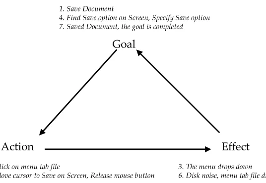
Cyclic interaction theory (Monk, 1998a) may describe the saving task in a relatively comprehensive way for average designers. Here, the overall goal “save document” leads the user to take some action. As this is a GUI the user can scan the screen for something that might do this. The user recognizes the “File“ menu tab. The user can click on it. We can describe that as taking the action “click on menu tab file”. Clicking on the menu tab makes the display change, the menu drops down. This can be described as an effect. The visible effects of the user’s action lead the user to change their goals. The goal “Save the Current Document” leads the user to generate the subgoal “Find Save option on Screen”. The effect “File menu drops down” can lead the user to replace this subgoal with another subgoal “Specify Save option”. The new goal set and new display state lead to a new action and the cycle continues. Figure 3 depicts a simplified mechanism of cyclic interaction. It characterizes these cyclic processes.
Yet, a critical factor, which will determine whether cyclic interaction theory achieves the uptake from average designers, is the effort required by the designers to apply cyclic interaction theory to a practical design. In short, a useful notation and methods make cyclic interaction theory be more usable in designing interactions.
As a way of effectively handling the interaction modelling from the viewpoint of the designer, we introduce an interaction model called the ‘Interaction Unit’ to accommodate the perspectives above. Throughout this paper, we will refer to two features of the conceptual model, the mechanism that the model employs and the benefit it provides in the design domain.
Goal
Action Effect
1. Save Document
4. Find Save option on Screen, Specify Save option 7. Saved Document, the goal is completed
2. Click on menu tab file
5. Move cursor to Save on Screen, Release mouse button
3. The menu drops down
6. Disk noise, menu tab file disappear
[image:3.595.147.415.490.675.2]2 How cyclic interaction can be described?
Some HCI theorists (e.g., Howes, 1994; Howes & Payne, 1990; Kitajima & Polson, 1995; Monk, 1998a; Norman, 1988) have claimed that cyclic interaction models are able to depict how a user interacts with a system in terms of a continuous cycle with goals, actions, effects, and recognition. It can account for the intimate connection between goal, action and the environment. Goals in conjunction with some
perception of the state of the environment lead to actions having some effects on the environment. These effects lead to changes in what is perceived and to new goals leading to new actions and so on.
Yet, some existing notations for cyclic interaction theory are less effective in representing the nature of cyclic interaction; for instance, either there is no notational scheme (e.g., Norman’s seven stages model, 1988), or there are implicit notations concerning how system effects modify user’s goals (e.g., D-TAG, Howes et al, 1990; Kitajima’s theory, 1995).
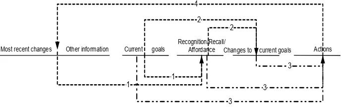
Combining the ideas addressed above, Ryu and Monk (Ryu & Monk, 2004) envisage cyclic interaction as shown in Figure 4, in order to model interactions explicitly with a more elaborated and conceptual manner. The general mechanism for the description of cyclic interaction in Figure 4 is as follows:
Arrow 1 [Perception]: The user processes most recent changes, along with other unchanged information available about the system; this processing is conditioned by the current goals.
Arrow 2 [Goal reorganization process]: The processing results in changes to the current goals; this is also conditioned by the current goals.
Arrow 3 [Goal-Action matching]: The new goal stack obtained by adding the goal changes to the current goals leads to another action; the choice of action also depends on the processing in Recognition/Recall/ Affordance.
Arrow 4: Some action by the user leads to some changes on the system, and the cycle continues.
One way of realizing this idea is also portrayed in Figure 5 in a standard tabular format. It depicts how the cyclic interaction model can model the task “Save a file” which has been described with GOMS in Figure 2. How this works is explained in the next section.
Most recent changes Other information Current goals Recognition/Recall/Affordance Changes to current goals Actions
1 1
2 2
3
3 3
4
[image:4.595.63.408.473.581.2]
Figure 4. Capturing cyclic interaction in our interaction design framework. 1: Perception (Recognition/
Recall/Affordance), 2: Goal reorganization process, 3: Goal-Action matching, 4: An action leads to the changes on the environment.
3 Interaction Unit (IU) model
3.1. Interaction Unit (IU)
In the analysis and design of interaction, the three key elements are the user (or human), the system (or the computer), and the interaction which takes place (Monk, 1998a; Norman, 1988). The purpose of the model proposed here is to relate the three key components to interaction design with a range of theoretical modelling and analytic techniques. We believe this will be accomplished by the detailed description of both what triggers the interaction and what the interaction achieves.
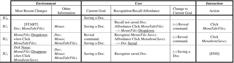
Each interaction unit (IU), which encompasses both the description of goals and the inspectable states of the system, accounts for how the user will take each action. See Figure 5. The task ‘Save a Doc’ on Microsoft Word™ is achieved by two actions: ‘Click MenuTab(File)’ and ‘Click MenuItem(Save)’. Consequently, there are three interaction units to describe the task, including the two actions (IU1 and IU2) and the last interaction (IU3) to check whether the task has been completed or not.
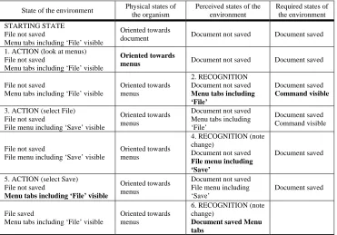
The development of an IU owes much to the works of Monk (1998a; 1999), who has claimed that cyclic interaction can be described in terms of both states and transitions. In his state transition framework for representing cyclic interaction, goals and effects are described as ‘states’ at the user and the environment respectively; action and recognition are described as ‘transitions’ (see Figure 6). Each transition describes interactions, beginning from a transition to trigger subsequent interactions and changing the state
variables to define each interaction.
Environment User Interaction
Most Recent Changes Other
Information Current Goal Recognition/Recall/Affordance
Change to
Current Goal Action
IU0 Saving a Doc.
IU1
[START]
Doc; MenuTab(File). Mouse. Saving a Doc.
Recall not saved Doc; Affordance Click MenuTab(File)
--> Menu(File) Dropdown.
(+) Reveal command.
Click
MenuTab(File).
IU2
Menu(File) Dropdown; when Click
MenuTab(File).
Doc; Mouse; MenuTab(File).
Reveal command; Saving a Doc.
Recognize Menu(File-Save); Affordance Click MenuItem(Save)
--> Doc Saved.
(-) Reveal command.
Click
MenuItem(Save).
IU3
Disk Noise; Menu(File) Disappear; when Click MenuItem(Save).
Doc; Mouse; MenuTab(File).
Saving a Doc. Recognize saved Doc. (-) Saving a
[image:5.595.100.548.346.468.2]Doc. [END]
Figure 5. An IU scenario for ‘saving a file’ example that has been described with GOMS in Figure 2.
Another crucial philosophy behind the development of the state transition framework is that a cycle of activity starts with the state of the world and recent system responses with the user acting on the world in response to the current state. Consequently, the environment is described before the other descriptions are represented.
These two principles of the State-Transition Scenario (STS) are still the basis for an informal understanding of the interaction unit. In short, the concept of interaction unit (IU) is similar to the descriptive unit of the state transition framework, but provides a comprehensive account of the
interaction. Consider both Figure 5 and 6 that model the same task ‘Saving a file’ in a different way. The first thing to notice is that the IU model is much more compact. This is because STS describes the two state-transitions, i.e., action and recognition. We argue that action is the more obvious focus for design than recognition, and recognition has to be considered as one of the cues for decision-making leading to the next user action.
The description using interaction units begins from the details of environments. See Figure 5. The first two columns in IU1 (IU0 describes the initial condition, indicating the overall goal of the task)
specify the inspectable part of the system state relevant to the action specified in the last column which is to “Click MenuTab(File)”. This can be thought of as a model of how the environment prompts a user to take some action. Inserted into this system model is a user component that specifies how the environment relates to the user’s goals.
State of the environment Physical states of the organism
Perceived states of the environment
Required states of the environment
STARTING STATE File not saved
Menu tabs including ‘File’ visible
Oriented towards
document Document not saved Document saved
1. ACTION (look at menus) File not saved
Menu tabs including ‘File’ visible
Oriented towards
menus Document not saved Document saved
File not saved
Menu tabs including ‘File’ visible
Oriented towards menus
2. RECOGNITION Document not saved
Menu tabs including ‘File’
Document saved
Command visible
3. ACTION (select File) File not saved
File menu including ‘Save’ visible
Oriented towards menus
Document not saved Menu tabs including ‘File’
Document saved Command visible
File not saved
File menu including ‘Save’ visible
Oriented towards menus
4. RECOGNITION (note change)
Document not saved
File menu including ‘Save’
Document saved
5. ACTION (select Save) File not saved
Menu tabs including ‘File’ visible
Oriented towards menus
Document not saved File menu including ‘Save’
Document saved
File saved
Menu tabs including ‘File’ visible
Oriented towards menus
6. RECOGNITION (note change)
[image:6.595.86.457.113.372.2]Document saved Menu tabs
Figure 6. State-transition scenario (STS) for ‘saving a file’ example. The changed states are given in bold – adapted from Monk (1999).
3.2. Modelling cyclic interaction with IUs
We have discussed how the interaction unit can be used to represent interactions, and now it is time to turn our attention to how the designer can use interaction units in a practical design process.
The environment part of an IU is broken down into two parts: Most Recent Changes and Other Information (see Figure 5). These are changes as a result of the last action taken by the user or previous system states that can describe the environment. Interaction units are arranged in sequences to describe a scenario of use. Thus the first column ‘Most Recent Changes’ generally specifies the changes that resulted from the last action. IU1 is the first IU in the scenario in Figure 5. As there is no most recent
change the designer must specify what elements of the standing system state the user will use to prompt the appropriate action. For example, the most recent change ‘Doc; MenuTab(File)’ in IU1 includes the
initial information prompting the user; yet the most recent change ‘MenuTab(File) Dropdown’ in IU2 is
generated by the last action ‘Click MenuTab(File)’. While we assume that most IU will be triggered by a change in the environment there are occasions where unchanged inspectable effects influence user behaviour. These are listed in the column ‘Other Information’. These may be previous effects that condition the current IU. This concept refers to restricting user interactions that can take place at each interaction unit. This is a key aspect of understanding what the users will be doing when carrying out their tasks. For instance, ‘Mouse’ defines an input device or interaction style with which the user has to interact.
Viewing Figure 5 as a whole one can run down the last column (Interaction/Action) to see actions that form the scenario. The first two columns (Environment) describe the primary responses of the system to these actions. The other columns (User) flesh out the implicit assumptions of the designer about how the user comes to take their part in this interaction in terms of goal changes and processing the display.
Changes to goals are prefixed with a plus (+) sign that means newly generated goals or a minus (–) sign that indicates elimination of goals. Take IU2 in Figure 5, the initial goal stack is ‘Reveal command’
and ‘Saving a Doc’. Recognition of the new display causes change to these goals, eliminating ‘Reveal command’. The new goal stack is thus ‘Saving a Doc’. An action following from this and the affordance presented by MenuItem(Save) on the keypad is to “Click MenuItem(Save)”.
How goals would be modified entirely depends on the user’s cognitive process. Consequently, to create a complete interaction model for average designers, it is necessary to describe these processes in a simple way for practical design decisions. IUs consider three cognitive attributes regarding how a user can proceed their interaction generating new goals or some actions taken. In other words, the IU notation focuses on the different roles of the three cognitive attributes: Affordance, Recall, and Recognition.
Objects in the system have affordance (Djajadiningrat et al, 2002; Gibson, 1979; Norman, 1999), which directly guides users’ expectations of what actions can be taken on the object and what effects these actions will have. In this paper, affordance is considered as recognition of an object that can be used to take some action and the effects that will result. For instance, in IU1 of Figure 5, the recognition of
‘MenuTab(File)’ on Microsoft Word allows a user to push it. Also, ‘Affordance Click MenuTab(File)’ allows the user to expect that a desired effect will be accomplished, i.e., ‘Menu(File) Dropdown’.
In contrast, Recognition refers to the understanding of the meaning of the object. From the viewpoint of designers, it is necessary to distinguish affordance from recognition in that the affordance of an object strongly suggests the next action rather than recognition. Recall is considered as remembrance of an event occurred in the past. This has been less considered in the previous work such as display-based interaction models (e.g., D-TAG; Howes & Payne, 1990). Consequently there is no account of the interaction history used as a resource (Wright et al, 2000) which may characterize the selection of an action. These efforts to distinguish the three cognitive attributes emphasize how the designer’s expectation of the user’s behaviour can be encoded in objects and how the user can translate or notice the designer’s idea. These psychological considerations in the IU model do not require the average HCI designer to describe how this process can be achieved in greater detail as has been suggested for most user models. Rather, the designer describes what cognitive process of the three cognitive processes may be involved in performing interactions. These simplified cognitive processes detect differences between the current goals, the overall goals and the perceived state of the world, and thus trigger changes to the current goals. For example, the environment in IU3 has ‘Disk Noise; Menu(File) Disappear’. When users
recognize the effect and evaluate this with the current goal stack, they can see that the overall goal has been achieved. In effect, the designer can simulate how the user will react or think in performing tasks using their proposed design. By asking the designer to conceptually describe just one way the user may complete the task, rather than a model that can cope with all contingencies, we further simplifies the task. Figure 7 depicts general steps for describing interactions with interaction units.
In this section, we have seen how the IU model can describe cyclic interaction. The next section will discuss how the IU model can highlight some interaction problems in developing a user interface.
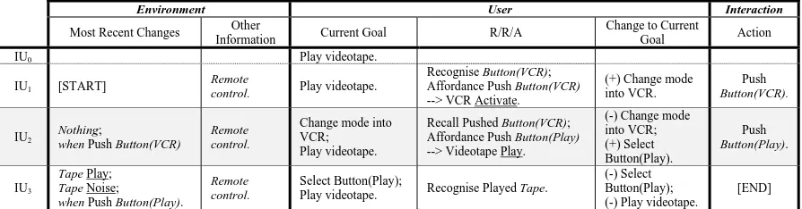
4 A case study: predicting mode problems with IUs
Consider for example a computer system where the effect of the actions taken depends on what mode it is in. The classic example is the text editor where in one mode keystrokes are interpreted as commands and in another as inserted text. Unless mode is clearly signalled people will make mode errors.
Modes give rise to two problems. The first is that a system may not immediately provide a user with the affordance to do what they want to do. This kind of mode problem is commonly observed when users interact with complex systems. Ryu and Monk (2004) claimed that this kind of mode presence could be detected by examining the Most Recent Change columns in all IUs looking for different effects arising from the same action.
pressed last. If someone else has used the remote control since you did, even this is impossible, resulting in much confusion. This is represented in IU2 of Figure 8. That is, in order to figure out the current mode
the user have to remember which button was pressed last. Such notations with recall, “Recall Pushed Button(VCR)”, will allow the previous action to change the perception of the environment and the current goal set at a given IU. In effect, one should then examine the Recognition/Recall/Affordance columns in the IUs immediately preceding the IUs thus identified to check that a mode change is made.
In this way, having written a complete IU modelling for some parts of a system the designer is asked to examine for IUs where the same action has a different effect indicating that the system has modes or the mode change has to be recalled.
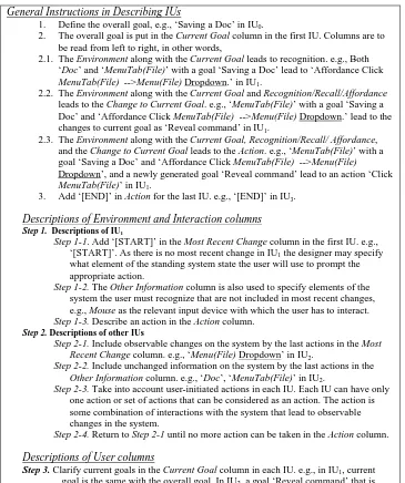
General Instructions in Describing IUs
1. Define the overall goal, e.g., ‘Saving a Doc’ in IU0.
2. The overall goal is put in the Current Goal column in the first IU. Columns are to be read from left to right, in other words,
2.1. The Environment along with the Current Goal leads to recognition. e.g., Both ‘Doc’ and ‘MenuTab(File)’ with a goal ‘Saving a Doc’ lead to ‘Affordance Click MenuTab(File) -->Menu(File) Dropdown.’ in IU1.
2.2. The Environment along with the Current Goal and Recognition/Recall/Affordance leads to the Change to Current Goal. e.g., ‘MenuTab(File)’ with a goal ‘Saving a Doc’ and ‘Affordance Click MenuTab(File) -->Menu(File) Dropdown.’ lead to the changes to current goal as ‘Reveal command’ in IU1.
2.3. The Environment along with the Current Goal, Recognition/Recall/ Affordance, and the Change to Current Goal leads to the Action. e.g., ‘MenuTab(File)’ with a goal ‘Saving a Doc’ and ‘Affordance Click MenuTab(File) -->Menu(File) Dropdown’, and a newly generated goal ‘Reveal command’ lead to an action ‘Click MenuTab(File)’ in IU1.
3. Add ‘[END]’ in Action for the last IU. e.g., ‘[END]’ in IU3.
Descriptions of Environment and Interaction columns
Step 1. Descriptions of IU1
Step 1-1. Add ‘[START]’ in the Most Recent Change column in the first IU. e.g., ‘[START]’. As there is no most recent change in IU1 the designer may specify what element of the standing system state the user will use to prompt the appropriate action.
Step 1-2. The Other Information column is also used to specify elements of the system the user must recognize that are not included in most recent changes, e.g., Mouse as the relevant input device with which the user has to interact. Step 1-3. Describe an action in the Action column.
Step 2. Descriptions of other IUs
Step 2-1. Include observable changes on the system by the last actions in the Most Recent Change column. e.g., ‘Menu(File) Dropdown’ in IU2.
Step 2-2. Include unchanged information on the system by the last actions in the Other Information column. e.g., ‘Doc’, ‘MenuTab(File)’ in IU2.
Step 2-3. Take into account user-initiated actions in each IU. Each IU can have only one action or set of actions that can be considered as an action. The action is some combination of interactions with the system that lead to observable changes in the system.
Step 2-4. Return to Step 2-1 until no more action can be taken in the Action column.
Descriptions of User columns
Step 3. Clarify current goals in the Current Goal column in each IU. e.g., in IU1, current goal is the same with the overall goal. In IU2, a goal ‘Reveal command’ that is generated in IU1 is put in the Current Goal column in IU2.
Step 4. Define the possible recognition/recall/affordance in the R/R/A column in each IU. Step 5. Specify the process of goal construction-elimination in the Change to Current Goal
column. e.g., the goal ‘Reveal command’ is popped out in IU2.
[image:8.595.51.416.224.660.2]Step 6. Return to Step 3 until overall goal is completed.
Figure 7. General procedures to present an interaction scenario using the IU model – refer to Figure 5.
Environment User Interaction
Most Recent Changes Other
Information Current Goal R/R/A
Change to Current
Goal Action
IU0 Play videotape.
IU1 [START]
Remote
control. Play videotape.
Recognise Button(VCR); Affordance Push Button(VCR) --> VCR Activate.
(+) Change mode into VCR.
Push
Button(VCR).
IU2
Nothing;
when Push Button(VCR)
Remote control.
Change mode into VCR; Play videotape.
Recall Pushed Button(VCR); Affordance Push Button(Play) --> Videotape Play.
(-) Change mode into VCR; (+) Select Button(Play).
Push
Button(Play).
IU3
Tape Play; Tape Noise;
when Push Button(Play).
Remote control.
Select Button(Play);
Play videotape. Recognise Played Tape.
(-) Select Button(Play); (-) Play videotape.
[image:9.595.108.555.114.231.2][END]
Figure 8. An IU model including recall. If someone wants to play a videotape, s/he has to recall button ‘VCR’ was pressed last.
5 Conclusion
In this paper, we have presented a model for the description of interaction, which is expected to be suited to a practical design process. Having introduced the interaction model, the IU model, we have identified differences between it and other HCI models from various stances. This has highlighted the advantages and limitations of the IU model in designing an interface. We have also seen that there are two bodies of work behind the interaction unit model. Firstly, the theoretical background of the IU model owes much to cyclic interaction theory. Second, the way of describing interactions is closely related to the principles of STS. It can also be seen that the IU model has advanced STS in order to provide a better ease-of-use model for designers with a more elaborated method.
Also, we demonstrated how the IU model could detect mode situations in a user interface. Similar procedures can be used to check other aspects of interaction units, for example, that the system prompts the user to establish and eliminate subgoals appropriately or that affordances prompt the right actions given a particular goal (Ryu, 2003). In this way, a designer can make fully explicit the
assumptions made about why the user should interact in a particular way. In this process the design is refined and made mode usable.
In conclusion, a user interface designer is not able to find guidelines that cover every new technology. This paper may shed light on the theoretical approach within the cyclic interaction design framework, which intends to support the designer in developing new interfaces. This provides an opportunity to reduce the development time of the new kind of interface rather than establishing all relevant design guidelines.
6 References
Card, S. K., Moran, T. P., & Newell, A. (1983). The Psychology of Human-Computer Interaction. Hillsdale, NJ: Erlbaum.
Djajadiningrat, T., Overbeeke, K., & Wensveen, S. (2002). But how, Donald, tell us how? on the creation of meaning in interaction design through feedforward and inherent feedback. Paper presented at the DIS 2002, London.
Gibson, J. J. (1979). The ecological approach to visual perception. Boston, MA: Houghton-Mifflin. Howes, A. (1994). A model of the acquisition of menu knowledge by exploration. Paper presented at the
Howes, A., & Payne, S. J. (1990). Display-based competence - towards user models for menu-driven interfaces. International Journal of Man-Machine Studies, 33(6), 637-655.
Kitajima, M., & Polson, P. G. (1995). A comprehension-based model of correct performance and errors in skilled, display-based, human-computer interaction. International Journal of Human-Computer Studies, 43(1), 65-99.
Monk, A. (1990). Action-Effect Rules - a Technique For Evaluating an Informal Specification Against Principles. Behaviour & Information Technology, 9(2), 147-155.
Monk, A. (1998a). Cyclic interaction: a unitary approach to intention, action and the environment. Cognition, 68(2), 95-110.
Monk, A. (1998b). Lightweight techniques to encourage innovative user interface design. In L. Wood (Ed.), User Interface Design: Bridging the Gap from User Requirements to Design (pp. 109-129): CRC Press.
Monk, A. (1999). Modelling cyclic interaction. Behaviour & Information Technology, 18(2), 127-139. Norman, D. A. (1988). The Psychology of Everyday Things: Basic Books.
Norman, D. A. (1999). Affordance, conventions, and design. ACM Interactions, 38-42.
Payne, S. J., & Green, T. R. G. (1986). Task-action grammars: a model of the mental representation of task languages. Human-Computer Interaction, 2, 93-133.
Polson, P. G., Lewis, C., Rieman, J., & Wharton, C. (1992). Cognitive walkthroughs - a method for theory-based evaluation of user interfaces. International Journal of Man-Machine Studies, 36(5), 741-773.
Rasmussen, J. (1986). Information Processing and Human-Machine Interaction: An Approach to Cognitive Engineering. New York: North-Holland.
Ryu, H. (2003). Modelling cyclic interaction: an account of goal-elimination process. Paper presented at the CHI 2003, Ft. Lauderdale, FL.
Ryu, H., & Monk, A. (2004). Will it be a capital letter: signalling case mode in mobile devices. Interacting with Computers, Revised.
Vicente, K. J. (1999). Cognitive Work Analysis: Towards Safe, Productive and Healthy Computer-Based Work. Mahwah, NJ.: Erlbaum.