Modeling and Assessment of an Experimental Combined
Evacuated-Tubes-Direct-Flat-Plate Solar Heater
Fouad Kamel Abdalla
Advanced Energy Centre, 96 Aorangi Road, Bryndwr, Christchurch, New Zealand
Ph.: (+64) 3 3515213 e-mail: fouadmk@xtra.co.nz
Abstract
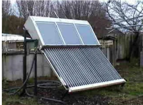
This research aims at investigating and assessing the performance of a solar heater combining the flat-plate collector and the evacuated-tube technologies. The flat 430-liter tank is working as manifold for the 1530 mm-long 47mm-external-diameter evacuated tubes as well as a direct receiver of heat supplied by three flat-plate double-glass collectors 0.5m2-aperture-area each as shown in Figure 1. Experimental investigation was carried out where the system was subjected to normal outdoor meteorological conditions and specifically defined operating conditions. The main goal of the testing procedure is to quantify the system's physical parameters and to allow modeling the system enabling a reliable prediction of long-term system performance under any set of meteorological and operating conditions.
Keywords
Evacuated tubes Flat-plate solar water heaters
1. INTRODUCTION
The Evacuated Tubes Collectors (ETCs) of the direct heating type - water in glass - usually use a manifold to collect the water being heated in the tubes. Normally, a storage tank is fulfilling the role as a manifold for hot water as well. Morrison et al (2001) have investigated these collectors for operation as a solar pre-heater for a range of locations. Daily test results showing useful energy gain vs. irradiation and the annual performance for different locations in Australia, China and Europe using a correlation model have been presented. They concluded ETC have been shown to operate effectively in a range of climate conditions. An ETC can easily achieve during its operation relatively high water temperature levels approaching 100 oC. Operating the collector at such high temperatures induce considerable losses in form of latent heat working to evaporate the water into steam and excessive heat losses due to the wide difference to the ambient temperature. Previous investigations by F. K. Abdalla, et. al. (2001) have shown that in case of ETCs, tanks with limited water capacity excessively high water temperatures, close to boiling point, might easily occur. This can effectively cause considerable heat losses mainly by radiation. In order to allow a higher heat capacity and lower average water temperature, a large tank volume of 430 litre has been designed for the present prototype. The tank is flat-shaped - in contrast to usually circular cylindrical tanks - to better fit architectural features in a building as shown in Figure 1.
[image:1.595.206.439.561.732.2]
As a result, the tank surface facing the sun became an attractive source of receiving a considerable amount of solar radiation, which is falling anyway on this surface. By transforming this surface into a flat-plate collector, heating directly the water in the tank an energy gain is guaranteed against reasonable additional investment.
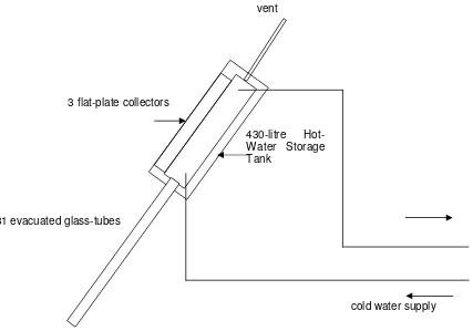
[image:2.595.68.495.211.510.2]This research aims at investigating and assessing the performance of a solar heater combining the flat-plate collector and the evacuated-tube technologies. The flat 430-litre tank is working as manifold for the 31 evacuated tubes, each 1530 mm-long, 47mm-external-diameter. The total aperture area of the evacuated-tubes collector (ETC) is 3.374 m2. The sun facing side of the tank has three aperture areas forming direct flat-plate collectors (FPC) of 0.5m2 each totaling 1.5m2. The FPCs are fitted with double-glass to improve thermal insulation and general performance. The physical system is shown in Figure 1 and represented schematically in Figure 2.
Figure 2. Schematic representation of the combined SWH.
2. THE MODEL
Generally, the heat gain in a SWH collector may be described by a modified Hottel-Whillier-Bliss, (1955) equation:
Qc = AcFR[(τα)G-UL(Tci-Tca)] (1)
where:
Qc heat gained by collector kJ
Ac collector aperture area, m 2
FR heat removal factor regarding inletcollector temperature
τα optical efficiency of collector-average transmittance-absorptance product including incident angle modifier
G irradiance, W/m2
UL overall heat loss coefficient of the collector, W/(Km 2
)
T collector inlet temperature, oC
cold water supply 3 flat-plate collectors
31 evacuated glass-tubes
vent
Tca collector ambient temperature, o
C
The model takes into account:
1. heat losses to the environment
2. thermal interaction of the storage with the collector (heat gain or extraction through directly connected inlet and outlet)
3. extraction of heat to the user
4. internal conduction and mixing effect between the layers (mixing is mainly caused by turbulence but also could be induced by thermal bridges and storage wall conduction)
With inlet Tci and outlet Tco water temperatures, the useful energy Qu is generally given by:
Qu = mcp (Tco-Tci) (2)
where
cp the specific heat of water and
m mass flow rate of water
The instantaneous energy gain in the system may be described as:
Qc = CdTs/dt + mdcpTs (3)
where:
C mscp
C heat capacity of storage (kJ/K)
md demand flow rate, kg/s
ms storage water mass kg
Ts water temperature of well-mixed storage ( o
C)
An integrated collector storage system may be described by a single differential equation combining eqs. (1) and (3):
Ac Fm [(τα) G - UL (Ts-Tca)] = C dTs/dt + mdcpTs (4)
where: Fm heat removal factor regarding meancollector temperature
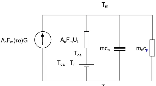
The differential equation (4) describes thermal networks may be represented by electrical analogies as described by M. Bosanac (1990) and depicted in Figure 3 where temperature differences are represented by potential differences and heat source by an electrical source. The conductivity mdcp represents the flow capacity rate of load and mcp the storage heat capacity (kJ/K), Tr reference (main) temperature (oC) and Tm mean temperature of the water in storage.
In this model the following pattern was assumed for the water replacement: the incoming water from the mains replaces the water in the bottom layer of the tank, the water in this layer in its turn replaces the water of the layer above, and so on.
The collector and storage performance are analyzed jointly, because of the feedback effect of the storage degree of stratification on the collector conversion efficiency.
Figure 3 Thermal network for operating period of the ICS system
Ac Fm [(τα) ∫op Gdt - UL ∫op (Tm - Tca) dt ] = mdcp∫op(Tm - Tr) dt + Qsop (5)
Where Qsop is the heat stored in the storage during operating period, kJ.
By rearranging the equation (5) we resolve to:
Ac Fm [(τα) ∫opGdt + UL ∫op (Tca- Tr)dt-UL ∫op(Tm-Tr)dt] = mdcp∫op(Tm-Tr)dt + Qsop (6)
Qsop = Ac Fm (τα) Hg + Ac Fm UL ϑac - (mdcp + Ac Fm UL) ϑm (7)
where:
Hg = ∫op Gdt
ϑac = ∫op (Tca - Tr) dt
ϑm = ∫op(Tm - Tr) dt
The heat extracted from the storage Qsol, kJ is calculated according to equation (2):
Qsol = mdcpϑm (8)
and by substituting ϑm from eq.(7) into eq.(8):
Qsol = mdcp (Ac Fm (τα) Hg + Ac Fm UL ϑac - Qsop) / (mdcp + Ac Fm UL) (9)
The instantaneous collector efficiency (η) which is defined as the ratio between the useful energy and the total radiation (G) incident on the collector surface area (Ac) can be expressed in the form:
η = FR [(τα)av - UL(Tci-Tca)/G] (10)
where (τα)av is the average transmittance-absorptance product. mdcp
mcp
Tr Tm
AcFmUL AcFm(τα)G
η = Qu/ Ac G (11)
η = ms cp (To- Ti) / Ac G (12)
The effective conversion efficiency η of the collector over operating period and To* the effective value of reduced temperature constant over operating period can be described in the following:
η = Fo(τα) - To*FoUL (13)
and
η = (Qsol + Qsop )/ AcHg (14)
where
Qsol heat extracted from the storage, kJ
Fo heat removal factor regarding outlet collector temperature and
To* = ∫op (Tco - Tca) dt / Hg (15)
3. TESTING PROCEDURE
The aim of the proposed testing is to identify the system parameters necessary for long term performance prediction.
The testing methodology includes:
1. The collector heat loss coefficient
2. The optical efficiency of the collector
This test encompasses a number of single-day measurements consisting of two main sequences:
1. Monitoring the energy flow during active conversion of solar energy.
2. Measuring the carry-over energy in the system at the end of the day.
Operating conditions:
1. Continuous load flow rate
2. Inlet storage temperature from the mains can be selected for daily measurement
In selection of these conditions we assume that design parameters of a system under the test are independent on the operating conditions.
The average value of air speed should be in the range 0-2 m/s (or 3-5 m/s if more site-specific) on the collector plane during the measurement in order to reduce data scattering due to the wind effect.
It is suggested that withdrawal flow rates in the range higher than 1.5 storage volume per hour.
The collector parameters may be identified by the least square fitting method. The closed loop mathematical models for identification of the parameters are given by eqn. (10).The parameters to be identified are the optical efficiency of the collector and the heat loss coefficient.
4. EXPERIMENTAL RESULTS
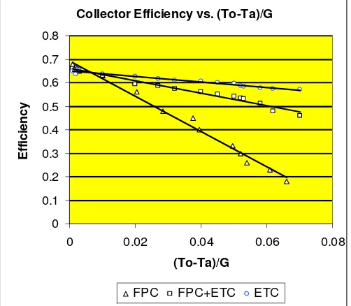
respectively, while in global radiation is +20W/m2. Figure 4 presents the variations of collector efficiency versus the reduced temperature parameter (To-Ta)/G.
Figure 4. Efficiency versus (To-Ta)/G for the solar collector in three configuration, i) flat-plate+ETC, ii) ETC and iii) flat-plate collector.
The scatter of the data is mainly attributed to the angle of incidence, wind speed and the dependence of UL on plate temperature. Also, the variations of the proportions of beam, diffuse and ground reflective components of solar radiation are participating in the data scattering. The collector is usually characterized by the line intercept FR(τα) and the slope - FRUL. The experimental data are fitted with linear equations to provide the characteristic parameters of the collector in order to allow a comparison for different configurations. The comparison with equation (3) results in FR(τα) = 0.66 and FRUL=4.47.
The data were fitted with linear regression and the intercepts and slopes of the linear equations are presented in Table 1 for the three tested cases. The Table depicts that the intercepts FR(τα) vary from to 0.68 for case i) flat-plate collector operated without the evacuated tubes to 0.65 for case ii) ETC operated without the flat-plate collector and further to 0.66 in case iii) for the complete unit ETC and flat-plate collector operating together, i.e. the optical efficiency of the collector is slightly independent on the configuration.
[image:6.595.182.433.112.331.2]The values of the heat losses FRUL listed in Table 1 are changing from 7.57, 1.14 to 2.71 for the three cases respectively. This indicated the strong dependence of FRUL on the configuration as expected.
Table 1 Characteristic parameters of the Solar Water Heater
Case FR(τα) FRUL R
2
i) FPC 0.68 7.57 0.971
ii) ETC 0.65 1.14 0.984
iii) FPC+ETC 0.66 2.71 0.992
5. DISCUSSION
In order to conclude the effect of the combination of the two technologies, evacuated Tubes Collector (ETC) and the flat-plate collector (FPC) on the collector performance three configurations have been compared. Figure 3 shows the efficiency variations versus reduced temperature parameter (To-Ta)/G. The solar collector with just the double-glass flat-plat collector shows a conventional optical efficiency FR(τα) of 0.68. The ETC operated separately achieves an FR(τα) of 0.65, while the combined system,
Collector Efficiency vs. (To-Ta)/G
0 0.1 0.2 0.3 0.4 0.5 0.6 0.7 0.8
0 0.02 0.04 0.06 0.08
(To-Ta)/G
E
ff
ic
ie
n
c
y
[image:6.595.71.495.590.666.2]ETC+FPC, achieves 0.66. On the other hand, the combined system is increasing the heat loss coefficient (UL) from 1.14 to 2.71 although achieving by far less (UL) than a separate FPC, i.e. improving (UL) from 7.57 down to 2.71. The combined effect of these two factors changes the intercept and slope of the efficiency curves. The effect of optical efficiency is dominant at low temperature difference, whereas the effect of heat loss in relevant at high temperature difference.
Thus, the efficiency of the compound ETC+FPC is generally less than the ETC separately. However, the energy gain achieved by adding the FPC aperture is giving advantage to the entire system, an energy which otherwise could be lost.
6. CONCLUSION
Opening windows forming direct flat-plate collectors (FPC) in the tank surface facing the sun, creating thus a compound system of ETC+FPC the following conclusions can be drawn:
- Increase in total energy gain of the system
- The total efficiency of the device will be generally reduced in contrast to a sole ETC system.
- Efficiency decline will be particularly sensitive to high temperature operation
- Efficiency of the combined ETC/FPC is generally improved compared to a sole FPC although
less than the sole ETC.
- By adding the FPC aperture additional energy gain is achieved giving advantage to the entire
system, an energy which otherwise will be lost.
7. REFERENCES
Abdalla Fouad Kamel and Wilson Paul (2001), Assessment of Domestic Evacuated Tube Direct Solar Water Heater, ISES Solar World Congress 2001, Adelaide, Australia 25 Nov. -2 Dec. 2001
Abdalla Fouad Kamel and Wilson Paul (2002), Optimum Operating Temperature for Evacuated Tube Solar Collectors, ANZSES Conference 2002, Newcastle, Australia 27-30 Nov. 2002
ASHRAE, Standard 93-86 (1986), American Society of Heating, Refrigeration and Air Conditioning Engineers, Methods of Testing to Determine the Thermal Performance of Solar Collectors, Atlanta, Georgia, USA, 1986
Bosanac M. (1990), A Test Method for Solar Water Heaters Characterization, Scientific Series of the international Bureau, Forschungszentrum Juelich GmbH, German Yugoslav Cooperation in scientific Research and Technological Development
Hottel-Whillier, evaluation of Flat-Plate Collector Performance, transactions of the conference on the Use of Solar Energy: the scientific basis, vol.II; part I, section A, p.p.74-104 (1955)