Aaron J. Parry
0050025590
ENG4112 Research Project Part 2 90323
PROJECT PERFORMANCE 29-OCT-2009
Faculty of Engineeri
*5056027*
*5056027*Student ID: Course: Class:
Assessment: Due Date: Submitted To:
Mark Given (Office use only): Marker Signature:
Tutor Name:
Tutorial Group Number: Room:
Day: Time:
Campus:
STUDENT DECLARATION:
I hold a copy of this assignment which I can produce if the original is lost or damaged.
I hereby certify that no part of this assignment has been copied from any other student’s work or from any other source except where due acknowledgement is made in the assignment. No part of this assignment has been written for me by any other person except where such collaboration has been authorised by the Course Team Leader or the examiner concerned.
Signature: Date:
Notes: 1. An Examiner or a Course Team Leader has, and may exercise, the right not to mark this assignment if the above declaration has not been signed.
Faculty of Engineering and Surveying
ENG4111 Research Project Part 1 & ENG4112 Research Project Part 2 DISSERTATION SUBMISSION FORM
STUDENT USE ONLY:
Student Name:
Aaron Parry
Student Number:
W0050025590
Program:
Bachelor of Engineering-- Electrical and Electronics
Mode:
On Campus
Project Title:
Remote Aerial Data Acquisition Concept -- RADAC
Supervisor/s:
Mr. Kerry Nufer and Dr. Alexander Kist
1 printed and soft bound assessment copy x
Inclusion of a Title page x
Inclusion of a Disclaimer page (it should be titled Limitations of Use) x
Inclusion of a signed Certification page x
Inclusion of Appendix A - Project Specification x
2 CDs containing a single PDF file identical to the printed copy (refer Project Reference Book section 11.11) x
I declare that I have submitted (Student to sign): Date:
Assignment Label Date Stamp Library Copy
Does the Supervisor give permission for a copy to be forwarded to the Library?*
* If a formal undertaking of Confidentiality has been given, then both CD copies will remain with the Supervisor (refer 6.4 of the Project Reference Book).
USQ collects personal information to assist the University in providing tertiary education and related ancillary services and to be able to contact you regarding enrolment, assessment and associated USQ services. Personal information will not be disclosed to third parties without your consent unless required by law.
USQ collects personal information to assist the University in providing tertiary education and related ancillary services and to be able to contact you regarding enrolment, assessment and associated USQ services. Personal information will not be disclosed to third parties without your consent unless required by law.
University of Southern Queensland
Faculty of Engineering & Surveying
Remote Aerial Data Acquisition & Capture Project
Remote Aerial Data Acquisition & Capture Project
Remote Aerial Data Acquisition & Capture Project
Remote Aerial Data Acquisition & Capture Project
(RADAC)
(RADAC)
(RADAC)
(RADAC)
A dissertation submitted by
Aaron Parry
In fulfillment of the requirements of
ENG4111/2 Research ENG4111/2 Research ENG4111/2 Research ENG4111/2 Research
Project ProjectProject Project
Towards the degree of
Bachelor of Electrical and Electronic Bachelor of Electrical and ElectronicBachelor of Electrical and Electronic
Bachelor of Electrical and Electronic EngineeringEngineeringEngineeringEngineering
ii
Abstract
The RADAC Project encompasses the design and prototype
implementation of a system for low-cost aerial data sensor
acquisition. It includes a Ground Transponder Unit (GTU), and Aerial
Interrogation System (AIS) mounted under an aircraft. The GTU
captures and transmits water-meter readings; the AIS initiates’
measurements and processes and displays the results. The proposed
system is based on RF devices in association with a small low-cost
single chip camera and microcontrollers.
During a consultancy to a large Queensland government authority
which has approximately 8000 water meters in regional and remote
parts of the state. It was realised that considerable savings could be
made in the management of water resources and human resources
needed to read these at three month intervals.
This project will calculate the RF subsystem performance in terms of
gain, beamwidth, return loss, bandwidth, and matching of the
antenna into the RF transceiver device Design Executive Data
Acquisition System and Design and implement Interrogation
Microcontroller and Design PCB for RF Transceiver and Design and
calculate power usage and Power Supply design and calculate
High-Gain Helical Antenna.
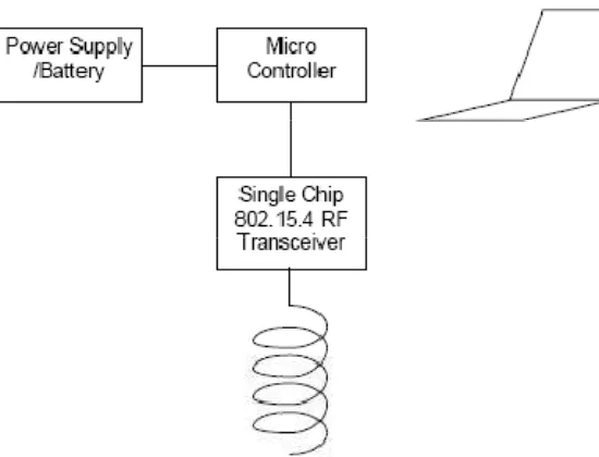
The solution based on using RF devices based on IEEE802.15.4 (IEEE
2006) in association with a small low cost single chip camera and
microcontroller. Figure 1 shows the Block Diagram of the Ground
Transponder Unit and symbolic AIS.
The potential saving in maintenance costs to industry by remotely
taking measurements is significant enough to warrant further
investigation with industry. There is the potential for its adaption in
University of Southern
Queensland Faculty of
Engineering and Surveying
ENG4111/2
Research Project
Limitations of Use Limitations of Use Limitations of Use Limitations of Use
The Council of the University of Southern Queensland, its Faculty of
Engineering and Surveying, and the staff of the University of Southern
Queensland, do not accept any responsibility for the truth, accuracy or
completeness of material contained within or associated with this
dissertation.
Persons using all or any part of this material do so at their own risk,
and not at the risk of the Council of the University of Southern
Queensland, its Faculty of Engineering and Surveying or the staff of the
University of Southern Queensland.
This dissertation reports an educational exercise and has no purpose or
validity beyond this exercise. The sole purpose of the course pair
entitled "Research Project" is to contribute to the overall education
within the student's chosen degree program. This document, the
associated hardware, software, drawings, and other material set out
in the associated appendices should not be used for any other purpose:
if they are so used, it is entirely at the risk of the user.
Prof F Bulle Prof F Bulle Prof F Bulle Prof F Bullennnn
iv 29/10/2009
Certification
Certification
Certification
Certification
I certify that the ideas, designs and experimental work, results, analysis and conclusions set out in this dissertation are entirely my own effort, except where otherwise indicated and acknowledged.
I further certify that the work is original and has not been previously submitted for assessment in any other course or institution, except where specifically stated.
Aaron Parry
Student Number: 0050025590
Signature
Acknowledgments
I would like to acknowledge the efforts of my project supervisors, Mr.
Kerry Nufer and Dr Alexander Kist, for their support and direction in
working through this project.
My wife Sarah for her understanding and support, my children
Storm, Skye, Kiara, and Ethan deserves thanks as well for putting up
vi
Table of Contents
Abstract ... ii
Acknowledgments ... v
Table of Contents ... vi
Table of Figures ... ix
List of Tables ... x
Glossary of Terms & Definitions ... xi
Chapter 1 Introduction ... 1-1
1.1 Project Description ... 1-1
1.2 Intellectual Property ... 1-1
1.3 Scope of Project ... 1-1
1.5 Project Methodology ... 1-2
1.6 Background ... 1-2
1.7 The Problem ... 1-3
1.8 A Possible Solution ... 1-3
1.9 Project Goals ... 1-3
1.10 Dissertation Outline ... 1-5
Chapter 2 Description ... 2-1
2.1 Literature Review ... 2-1
2.2 Consequential effects/implications/ethics ... 2-2
2.3 Risk Assessment ... 2-2
2.4 Resource Planning ... 2-2
2.5 Conclusion ... 2-3
Chapter 3 RADAC DESIGN ... 3-1
3.1 RADAC Block Diagram ... 3-1
3.2 Aerial Interrogation System (AIS) ... 3-1
3.3 Ground Transponder Unit ... 3-2
3.5 RADAC GTU Implementation Options ... 3-6
3.6 Dedicated Terrestrial Applications ... 3-6
Chapter 4 General Design ... 4-1
4.1 Simplicity ... 4-1
4.2 Adaptability ... 4-1
4.3 Cost ... 4-1
4.4 Ground Transponder Unit (GTU) Assembly ... 4-2
4.5 Printed Circuit Board ... 4-2
4.6 Microcontroller Unit (MCU) ... 4-2
4.7 Memory ... 4-5
4.8 Wireless Transceiver Module ... 4-6
4.9 Camera Module ... 4-7
4.10 Antenna ... 4-9
4.11 Radome ... 4-15
4.12 Radome Enclosure Adaptor... 4-16
4.13 Installation ... 4-16
4.14 Aerial Interrogation System... 4-17
4.15 Flooding Routing Protocol ... 4-18
4.16 Operating System ... 4-19
4.17 Software Architecture ... 4-20
4.18 Sensor ... 4-21
4.19 Network ... 4-23
Chapter 5 Specification ... 5-1
5.1 Common Specification ... 5-1
5.2 Ground Transponder Unit (GTU) ... 5-3
5.3 Aerial Interrogator Unit (AIS) ... 5-4
Chapter 6 Conclusions ... 6-1
Further work to be Completed ... 6-2
viii
Project Specification ... ii
Appendix B ... i
Calculations ... i
Electrical Current Usage of Circuit ... i
Solar Panel Calculations ... i
Beam Width and Gain Calculations ... ii
Antenna Calculations and Losses ... vi
Component Analysis ... xi
Appendix C ... i
Camera Code ... i
Appendix D ... i
Datasheets ... i
C328R Datasheet ... Pg 88-91i
C328R User Manual ... Pg 92-104i
C328-EV232 EV BOARD ... Pg 105i
Zigbee Applications Framework Whitepaper ... Pg 106-112i
AT45DB321D Datasheet ... Pg 113-166i
ATMEGA644PV Datasheet ... Pg 167-194i
Helical_Feed_Antennas Datasheet ... Pg 195-217i
Survey of Helical Antennas Datasheet ... Pg 218-240i
The Axial Mode Helix _etd_CH2 Datasheet ... Pg 241-254i
XbeeProZB Datasheet ... Pg 255-392i
Table of Figures
Figure 1 Aerial Interrogation System –Block Diagram ... 3-2
Figure 2 Ground Transponder Unit –Block Diagram ... 3-4
Figure 3 MCU ... 4-3
Figure 4 ATmega644PV microcontroller ... 4-4
Figure 5 Master/Slave Mode Communication ... 4-5
Figure 6 Pin Configuration of Data Flash Module ... 4-6
Figure 7 Data Flow in UART Interface Environment ... 4-7
Figure 8 Wireless Transceiver Module ... 4-7
Figure 9 Block Diagram of Camera Module ... 4-8
Figure 10 Camera ... 4-8
Figure 11 Overview of materials used and dimensions. ... 4-11
Figure 12 Stub Mounting ... 4-12
Figure 13 Almost finished helix antenna. ... 4-12
Figure 14 Finished 12 turn 2.4 GHz helix antenna ... 4-13
Figure 15 Return loss (dB) from 2300 - 2500 MHz ... 4-13
Figure 16 Smith chart 2300 - 2500 MHz ... 4-14
Figure 17 Ground Transponder Unit (GTU) Assembly ... 4-15
Figure 18 Aerial Interrogation System ... 4-17
Figure 19 Layering Structure of the Operating System ... 4-19
Figure 20 Data Flow ... 4-21
Figure 21 Modules Involve In Sensor Part ... 4-21
Figure 22 Format of Image Data Package ... 4-23
Figure 23 Modules Involve In Network Part ... 4-24
Figure 24 Format of Network Packet ... 4-24
Figure 25 Format of UART Data Frame ... 4-25
Figure 26 Flow Chart of the Receiving Data Mechanism ... 4-26
Figure 27 Risk Assessment ... xii
x
List of Tables
Table 1 Command Lists of the Camera Module ... 4-22
Table 2 Electrical current requirements of hardware ... i
Table 3 Antenna Calculations and Losses ... vi
Glossary of Terms & Definitions
AIS Aerial Interrogation System
GTU Ground Transponder Unit
POC Proof of Concept
RADAC Remote Aerial Data Acquisition &
Capture
RF Radio Frequency
UAV Unmanned Aerial Vehicles
JPEG Joint Photographic Experts Group; Also
the name of the imaging standard they
created.
PSNR Peak Signal-to-Noise Ratio, a common
measure of image quality, measured in
dB.
SNR Signal-to-Noise Ratio, a ratio of a signal
to the underlying noise, measured in dB.
dB Decibels, a measure of ratios.
ISO International Standards Organization
Baud rate The rate at which data flows
BCD Binary Coded Decimal
Binary Number system consisting of zeros and
ones only
Bit Binary Digit- smallest unit of storage in
a computer
Byte A group of eight data bits
CASA Civil Aviation Safety Authority
CASR Civil Aviation Safety Regulations
RTS/CTS Request to send/ clear to send
1-1
Chapter 1
Introduction
1.1
Project Description
The RADAC Project encompasses the design and prototype
implementation of a system for low-cost aerial sensor data
acquisition. It includes a Ground Transponder Unit (GTU), and
Aerial Interrogation System (AIS). The proposed system is based on
RF devices in association with a small low-cost single chip camera and
microcontrollers. The GTU captures and transmits water-meter
readings; the AIS initiates’ measurements and processes and displays
the results.
1.2
Intellectual Property
The concepts, design specifications, functionality and operation of
RADAC are the property of NUFER & Associates (Aust) Pty Ltd, and
the acceptance of these IP rights is necessary.
1.3
Scope of Project
The scope is limited to Proof of Concept (POC) in which the general
philosophy of the design is proven to work, as a first step to the
development of a commercial design by others. To this extent, the
POC shall focus on specific aspects of the design which are identified
1.5
Project Methodology
Since the project at this time is a ‘Proof-of-Concept’ the following
methodologies are used:
The hardware components in relation to the actual antennas, main
PCB, and mounting brackets are to be determined such that these
enable the manufacturability of these components to be evaluated as
a precursor to a final design – particularly in cost.
The actual electronics modules for the RF transceivers, camera
module, and microcontrollers, are to be off-the-shelf modules, which
utilise standard industry interfaces and allow the system functionality
and algorithms to be developed in the ‘basic’ language.
Once the parameters for the air-segment link are determined, the
antennas will be developed on an identical two-off basis so that these
can be tested into each other on a range, and then testing confirmed
using a standard dipole against each unit individually.
All hardware components for the proof-of-concept design will be able
to be sourced across the counter at any hardware retail outlet.
1.6
Background
It was realised recently during a consultancy to a large Queensland
government authority that the potential existed for considerable
savings in the management of water resources, through the
1-3
1.7
The Problem
The organisation in question has somewhere in the vicinity of 8000
water meters in regional and remote parts of the state as shown in
the photograph below. The units represent a considerable cost in
terms of replacement and the human resource needed to read these
at approximately three month intervals.
Further to this the replacement of the meters with digital units would
not necessarily result in many savings due to the ongoing cost of
reading the devices. Fitting the units with (RF) radio frequency
modules to interface into terrestrial radio network (where within
range) would also comprise a significant cost – both in terms of initial
capital cost and ongoing operational costs
1.8
A Possible Solution
Based on the continued evolution of low-cost RF devices and
associated technologies, NUFER & Associates (Aust) Pty Ltd have
determined that a possible solution based on IEEE802.15.4 RF based
devices (Zigbee, XBee) in association with a small low cost single chip
camera and microcontroller.
1.9
Project Goals
The goals of the Project, which shall be reflected in the deliverables,
shall comprise of the following –
Confirmation of the specifications by which a temporary radio link for
the transmission of data at a particular speed may be achieved
between a ground sensor (the GTU) and an overhead interrogation
altitude and antenna gain for the AIS to acquire, upload, and close
down the connection with the GTU:
Demonstration of the RF subsystem performance in terms of gain,
beamwidth, return loss, beamwidth, bandwidth, and matching of the
antenna into the RF transceiver device:
Demonstration of the required software algorithms for this process to
occur in a reliable and stable manner whereby:
The AIS is able to initiate and obtain contact with the GTU based on
the fact it is within the target area determined under part (a);
The AIS is able to confirm that the established connection with the
GTU is unique (based on the identification of the GTU), stable and
secure;
The AIS is able to, via the GTU, supervise the capture of an image
from the in-built camera system of the water supply gauge;
The AIS is able to, via the GTU, supervise the successful upload of
the image data captured from the step described above;
The AIS is able to, via the GTU, upload extraneous data including
battery status and temperature from the GTU;
The AIS is able to close down the connection with the GTU in a
controlled manner at the end of the upload process so that it can be
reinitialised at any subsequent time.
The GTU is able to carry out routine background tasks including
in-built integrity analysis interspersed with ‘sleep’ processes that
minimise power consumption to the utmost minimum:
Demonstration of an in-built power scavenging process which uses
1-5 Demonstration of RADAC functionality through the remote capture
and display of a water-meter dial display on a computer screen under
the MS Windows XP system, as a result of the user initiating the
capture process.
1.10
Dissertation Outline
This Dissertation comprises of six chapters. The first chapter briefly
describe about background, problem statement, objectives and
scope of the project.
The second chapter reviews previous related research that had been
conducted. This chapter states the information which helps to
develop the project.
The third chapter is about RADAC design. This chapter provides
information about the components used to prepare the RADAC
design of the project and why such components are chosen for this
project.
The fourth chapter reviews the General Design. The detailed
explanation about the hardware including the mechanism
involved, and the function of every component.
The fifth chapter describes the specifications set out at the
outset of the project, including the needs and wants for the
project.
The last chapter which is chapter six is the conclusion. There are
Chapter 2
Description
2.1
Literature Review
Research has been conducted into various other methods of remote
data acquisition. Of the available techniques RADAC fulfils all
requirements set out in the achievable outcomes. Factors have been
mentioned earlier in the report detailing project outcomes and how
these need to be implemented to achieve these goals.
Remote Data Acquisition through Internet Based Telemetry- This
experiment is to develop and implement an Internet Based Telemetry
system. Telemetry is science of automatically measuring or recording
data from one or more instruments and transmitting them over a
distance. This study researched the transmission of data remotely
acquisitioned over the internet. (See References)
Meter Readout System –
A method is presented for remote meter reading that addresses
upgrade needs for automatic periodical readout of meters lacking
electrical output signals. The solution embodied in the invention is a
self contained, fully enclosed, low energy solution with provisions for
onsite visual meter inspections. It can be implemented in various
applications, such as but not limited to, water meters, electricity
meters, gas meters, tachometers, and other meters. Methods are
incorporated that enables the user full control over the timing and
rate of the data acquisition, and control over system performance and
power consumption. (See References)
2-2 of counts presented to a display, which is used to calculate the
monthly bill. It has applications within the electricity, gas and water
utility industries for domestic, commercial and industrial applications.
Sub metering is often used within a building, retail or industrial
facility where it is desirable to measure power consumption for
specific equipment, locations or sub-level accounts. (See References)
2.2
Consequential effects/implications/ethics
If RADAC were to be implemented within the industry the
consequential effects on the industry would increase productivity,
decrease running costs and possibly increase technical knowledge of
the maintenance employees. Implementing RADAC could allow for
reduction in labour costs therefore allowing maintenance staff to be
invested in other areas of the industry.
2.3
Risk Assessment
RADAC has been designed with many factors in mind regarding safety
issues. One of the issues which have been assessed as a high risk is
the use of light aircraft given the possibility of and probability of an
aircraft incident. Even though this was deemed unlikely the
consequences of this were fatal. Other risks which were identified
include manual handling, strain injury, and abrasions. (See Risk
Assessment Matrix in Appendix B)
2.4
Resource Planning
The resources required for RADAC have been sourced off the shelf
where possible. Sources for the material used in the radon have been
sourced from the local hardware store. The microcontroller was
sourced from a local electronics store. The enclosure is off the shelf
project was born out of the realisation of possible savings in the
capture of information from legacy water meters.
2.5
Conclusion
The alternatives to RADAC are too cumbersome, technically unviable,
reliant on further technology, unadaptable to various applications.
The alternatives do not offer compatibility to all types of water meters
regardless of location and size. They also are unadaptable to given
climate and accessibility issues. The alternative remote meter reading
technologies biggest drawbacks is the costs to implement in
comparison to RADAC. The companies offer some comparison to
RADAC but do not fulfil all of the achievable outcomes with the
budget constraints of this project and deliver the outcomes specified.
There have been many projects encompassing the use of the many
separate components which are used in this project but these do not
use these technologies to perform the allotted tasks set out in this
3-1
Chapter 3
RADAC DESIGN
3.1
RADAC Block Diagram
In order to achieve the required functionality, the RADAC design
brings a number of components together in a low-cost housing and
associated antenna as described below. Essentially it comprises two
parts – an Aerial Interrogation System (AIS), and Ground
Transponder Unit (GTU).
3.2
Aerial Interrogation System (AIS)
As shown in Figure 1, the Aerial Interrogation System comprises four
components –
Executive Data Acquisition System – Typically running on a laptop or
similar computer platform with an integrated database which contains
the executive program responsible for supervising data acquisition
and storing same into a database.
Interrogation Microcontroller – For detailed supervision of the RF
transceiver device including acquisition and release of the
transponder along with responding with the lap-top serial link.
Single-Chip RF Transceiver – For actual implementation of the
interrogation process and data acquisition into the microcontroller.
Power Supply/ Battery – For independent powering of the AIS – Note
High-Gain Helical Antenna – For direction of the RF energy towards
the transponder using a circularly polarised RF signal and therefore
removing any potential effects of depolarisation between transceiver
[image:23.595.181.456.253.463.2]antennas and therefore optimising gain over the resulting link.
Figure Figure Figure
Figure 1111 Aerial Interrogation Aerial Interrogation Aerial Interrogation System Aerial Interrogation System System System –––Block Diagram–Block DiagramBlock DiagramBlock Diagram
Following a session of water-meter message captures, the database
would be processed to automatically generate evidentiary information
for billing of water supply usage, and could include the actual image
of the water meter concerned including the time and date of image
capture as well as other information.
3.3
Ground Transponder Unit
A block diagram of the Ground Transponder Unit (GTU) is shown in
3-3 A High-Gain Helical Antenna – For direction of the RF energy towards
the transponder using a circularly polarised RF signal and therefore
removing any potential effects of depolarisation between transceiver
antennas and therefore optimising gain over the resulting link.
Single Chip RF Transceiver – For communications and reception of
commands from, and streaming of data back to the AIS; ZigBee,
XBee uses IEEE 802.15.4 MAC and PHY layers aimed at simple,
low-cost wireless communication networks, and lower power consumption
than other wireless protocols such as Bluetooth due to its small size
stack (about 28Kb). It also supports ease of installation, reliable data
transfer, and short-range operation. Depending on the application, a
system network can be designed as either a star or peer-to-peer
topology which can be implemented as a mesh networking topology.
They are determined by the controller, called the PAN coordinator.
Transponder Microcontroller – For Interpretation of AIS command
data and subsequent supervision of response data stream following
communications with the CMOS camera; it consists of a
microcontroller unit - ATmega644PV is capable to operate with low
power consumption. The MCU is active with 398uA current, 0.027uA
in power-down mode, and 0.5uA in power-save mode. The
operating voltage is from 1.8V to 5.5V. The sensor node operates
with 3.3 V supply which is in the range of the MCU operating voltage.
CMOS Camera & Flash – Actual illumination and imaging of the meter
display back to the supervising microcontroller. A C328 CMOS camera
module was used for capturing an image. This component is designed
for low cost, and low power solutions for high resolution image
capture. It supports VGA/CIF/SIF/QCIF/ 160x128/80x64/3- 20x240
image resolutions. It also controlled with an RS-232 interface for
setup and data transfer. The unit has 115.2Kbps bandwidth for
0.75-6 fps. It is operated using 3.3V, 60mA, and low standby current
100 µA.
Battery & Solar Cell – For ongoing float charging of the built-in
battery and powering of the active electronic components contained
there-in.
[image:25.595.262.427.196.447.2]Figure
Figure Figure
Figure 2222 Ground Transponder Unit Ground Transponder Unit Ground Transponder Unit –Ground Transponder Unit –––Block DiagramBlock DiagramBlock DiagramBlock Diagram
In actual operation the AIS is therefore able to interrogate GTUs and
therefore obtain imaging of the water supply meter face, which is
stored into the database of the supervising computer on-board the
aircraft.
3.4
RADAC Method of Operation
Since water meters are scattered over large areas and are often
difficult to access from the ground due to their location through
locked gates and creek gullies etc. the use of an aerial vehicle for
3-5 In actual operation the following method of operation is therefore
envisaged.
An aircraft would be fitted with an AIS and the coordinates of GTUs
used as the basis for programming a flight path which incorporated a
number of way points for the purpose of tracking over and uploading
meter information.
In flight, the AIS would know where it was relative to each GTU based
on independent information being obtained from a GPS receiver
incorporated in the AIS.
On approaching the location of the GTUs the AIS would commence
transmission of a ‘wake-up’ signal which would bring the GTU out of
hibernation and ready for it to take a picture of the water meter dial.
On command, a picture would be taken of the water meter dial and
the data uploaded to the AIS where the image would be stored in the
database of the associated laptop computer.
Associated with this could be other information relating to the
state-of-health of the GTU and any other information associated with the
installation2 which may include temperature and weather records
over the period since the last reading.
Once the information capture had been completed, the GTU is put
back into hibernation, and the data saved into the data base of the
laptop for analysis and report.
On completion of the information upload the aircraft is then able to
track rapidly to the next site, or loiter in a holding pattern to recover
An extension to the GTU design would allow one transponder to
become a ground mounted router, for capture of information from
adjacent water meters using a local mesh, and therefore lower the
cost of GTUs in a cluster situation.
3.5
RADAC GTU Implementation Options
The design of the RADAC GTU is not restricted to aerial information
retrieval but may also be used for terrestrial applications or a mixture
of both. In these cases a combination of antennas oriented in the
required direction may be used to implement the design.
3.6
Dedicated Terrestrial Applications
In a dedicated terrestrial application Yagi antennas may be used to
connect the site to a point of information collection in the vicinity of
the site. Alternatively a combination of aerial space or helical
antennas and local ground based communications antennas may be
used for low-cost networking of data with a single router unit which is
responsible for relaying data between an overhead AIS and the GTU
4-1
Chapter 4
General Design
It is important that the design take into account appropriate
technologies and methodology of construction as part of
manufacturing and installation on-site.
4.1
Simplicity
It is essential that the design be as outwardly simple as possible in
that it comprises easily assembled structures and is easy to fit, and
maintain in the field.
4.2
Adaptability
In addition the design must allow fitment to the large range of water
meters in terms of host water pipe diameter, and gauge positioning
so that a common kit-of-parts can be used for a significant part or
the entire product.
4.3
Cost
The manufacturing cost must be low to leverage the increasingly low
cost of electronic devices and make the product viable in the business
case. At this time a manufacturing cost of $AUD50 is seen as the
target for the Ground Transponder Unit (GTU) in large quantities.
In the case of the Aerial Interrogator System (AIS), the cost may be
somewhat higher at around $AUD500 in recognition of the need to
attain compliance for aviation installation.
4.4
Ground Transponder Unit (GTU) Assembly
At this time the GTU is seen as comprising 100mm PVC tube which
contains the helical antenna for its entire length – connected at one
end to a PCB within the lower end of the tube. (Possible change of
enclosure material)
4.5
Printed Circuit Board
The upper side of the PCB will include the matching components and
connection to the feed-point of the antenna. This feed point will
extend through the PCB to the lower side which will be fitted with the
RF transceiver chip and associated electronic components as well as
the camera.
4.6
Microcontroller Unit (MCU)
MCU is the core component in every single sensor node. The
functions of this component is to control the activity of the sensor
node including data processing, serial communication which is
controlling other devices through several processes including
hardware interface, collecting data from devices or send data to
the devices, acknowledgement and so on.
ATmega644PV, produced by Atmel Corporation is chosen as the MCU
of the sensor node. It consists of two programmable serial USART
required for interfacing with camera module and wireless transceiver
module. Basically, USART operates by taking bytes of data and
transmit it to another USART bit by bit sequentially. Another
USART receives bits and reconstructs the bits to form complete
4-3 ATmega644PV is capable to operate with low power consumption.
The MCU is active with 398uA current, 0.027uA in power-down
mode, and 0.5uA in power-save mode. The operating voltage is
from 1.8V to 5.5V. The sensor node operates with 3.3 V supply
which is in the range of the MCU operating voltage.
Figure Figure Figure Figure 3333 MCUMCUMCUMCU
In addition, based on the device datasheet, the MCU consists of
64kbytes of In-System Self-Programmable Flash which compatible
for higher demand of the RAM size especially for the uses of an
operating system. The following Figure 4 shows the photo of
ATmega644PV and showing the pin configuration of ATmega644PV
4-5
4.7
Memory
The requirement of larger memory spaces to store temporary data
from MCU is solved using AT45DB321D data flash produced by
Atmel Corporation. The device operates with single supply from 2.7V
to 3.6V. The 3.3V supply of the sensor node is in the range of the
operating voltage of the data flash. The device also operates with
low power dissipation where 7mA active read current, 25KA
standby current and 5KA deep powers down.
The data flash communicates with MCU via full duplex synchronous
serial data link known as Serial Peripheral Interface (SPI). The
communications include input/output, device selection and clock is
done through four pins connected to MCU which are Serial Input
(SI), Serial Output (SO), Chip Select (CS) and Serial Clock (SCK).
The communication is in Master/Slave mode where MCU function as
the master while the data flash function as slave as shown in Figure
5 below.
Figure Figure Figure
Figure 5555 Master/Slave Mode CommunicationMaster/Slave Mode CommunicationMaster/Slave Mode CommunicationMaster/Slave Mode Communication
The capacity of AT45DB321D data flash is 32 megabit or equal to 4
Mbytes. The device has user configurable page size whether 512
bytes per or 528 bytes per page. Based on the device datasheet, it
consists of 34,603,008 bits of memory which are organized as
size configuration. The following figure, Figure 6 shows the pin
configuration of AT45DB321D data flash.
Figure Figure Figure
Figure 6666 Pin Configuration of Data Flash ModulePin Configuration of Data Flash ModulePin Configuration of Data Flash Module Pin Configuration of Data Flash Module
4.8
Wireless Transceiver Module
Communication between sensors node is done through the Zigbee,
XBee OEM RF modules manufactured by Maxstream. It is
manufactured to operate in compliance with IEEE 802.15.4
standard with several features in order to obtain low cost and low
power sensor node specifications. Transmitting and receiving data
are done within ISM 2.4GHz frequency band with 250kbps data rate.
The transceiver is able to operate in 4 modes which is transmit
mode, receive mode, idle mode and sleep mode which lead to
power saving. Furthermore, it operates at 3.3V with 45mA TX
current, 50mA RX current and less than 10uA power down current.
The transmitted power is 1mW which is equal to 0dBm. The signal
coverage radius is up to 30m at urban or indoor and up to 100m at
outdoor line-of-sight.
As stated previously, the wireless transceiver module
communicates with MCU through USART. Figure 7 illustrates the
4-7
Figure Figure Figure
Figure 777 Data Flow in UART Interface Environment7Data Flow in UART Interface EnvironmentData Flow in UART Interface EnvironmentData Flow in UART Interface Environment
environment. From the Figure, DI stand for Data In, DO stand for
Data Out while both CTS and RTS are Hardware Flow Control. Figure
8 shows the photo of XBee Module.
Figure Figure Figure
Figure 888 Wireless Transceiver Module8Wireless Transceiver ModuleWireless Transceiver ModuleWireless Transceiver Module
4.9
Camera Module
In order to retrieve graphical information in the sensor field, C328R
JPEG Camera Module is used. This camera is VGA camera module
consists of JPEG compression engine or JPEG CODEC which called
OV528 Serial Bridge. This module also has built-in serial type
program memory to store a set of command interfacing to MCU.
When the camera receives snapshot command from MCU, a
single-frame still picture with VGA resolution will be captured. Then the
picture will be compress by JPEG CODEC and it is sent to MCU
The features of C328R includes small in size where its dimension is
20x28mm, operation with 3.3V operating voltage and low power
consumption which is 60mA. The UART interface speed can be up to
115.2kbps and able to generate several size of JPEG compression
images from 80x64 pixels up to 640x480 pixels. Figure 9 illustrate
the block diagram of the camera module and follow by Figure 10
showing the photo of C328R.
Figure Figure Figure
4-9
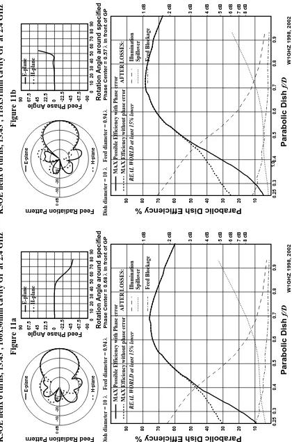
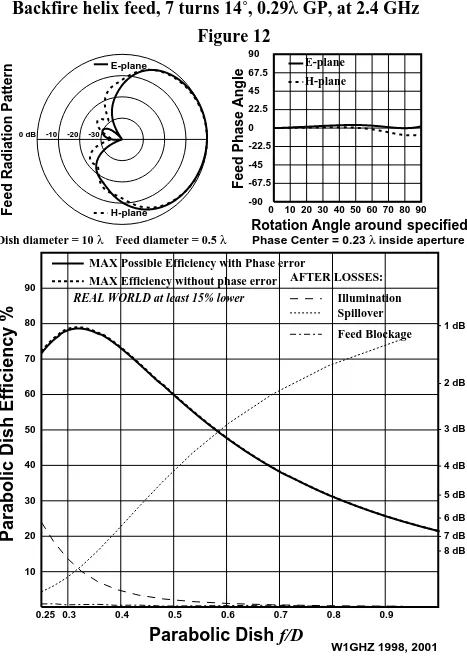
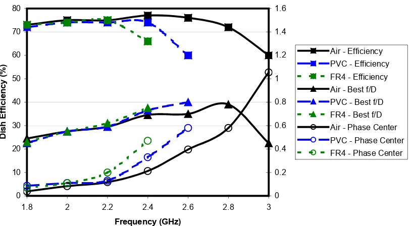
4.10
Antenna
A helical antenna has been identified as the most appropriate for the
design, owing to the fact that a reproducible gain device is required
for manufacturing purposes. As an option a 4 x patch array would be
an alternative suggestion, however, it is thought that this may be too
costly and required too-large an area to achieve the same gain as the
helical.
The helix antenna, invented in the late forties by John Kraus (W8JK),
can be considered as the genius ultimate simplicity as far as antenna
design is concerned. Especially for frequencies in the range 2 - 5 GHz
this design is very easy, practical, and, non critical. This contribution
describes how to produce a helix antenna for frequencies around 2.4
GHz which can be used for e.g. high speed packet radio (S5-PSK,
1.288 Mbit/s), 2.4 GHz wavelengths, and, amateur satellite (AO40).
Developments in wavelengths equipment result in easy possibilities
for high speed wireless internet access using the 802.11b (aka WiFi)
standard. The helix antenna can be considered as a spring with
N
N
N
N
turns with a reflector. The circumference (
C
C
C
C))))
of a turn isapproximately one wavelength (
llll))))
, and, the distance (d
d))))
d
d
between theturns is approx. 0.25
C
. The size of the reflector (R
R))))
R
R
is equal toC
orl
,and can be a circle or a square. The design yields circular polarization
(CP), which can be either 'right hand' or 'left hand' (RHCP or LHCP
respectively), depending upon how the helix is wound. To have
maximum transfer of energy, both ends of the link must use the
same polarization, unless you use a (passive) reflector in the radio
path.
The gain (
G
G
G
G
) of the antenna, relative to an isotropic (dBi), can beestimated by:
According to Dr. Darrel Emerson of the National Radio Astronomy
Observatory, the results from [1], also known as the 'Kraus
formula', are 4 - 5 dB too optimistic. Dr. Ray Cross inserted the
results from Emerson in an antenna analysis program called 'ASAP'.
The characteristic impedance (
Z
Z
Z
Z))))
of the resulting 'transmission line'empirically seems to be:
(2)
Practical design for 2.43 GHz
!
" #$
(3)
%&'&(&)*+,&(-), . /
(4)
Standard PVC sewer pipe with an outer diameter of 40 mm is perfect
for the job and can be obtained easily from a 'do it yourself' shop or a
plumber. The helix will be wound with standard wire used to
interconnect 240V AC outlets households. This wire has a colourized
PVC isolation and a 1.5 mm thick copper core. Winding it around the
PVC pipe will result in
D
= ca. 42 mm, due to the thickness of theisolation.
0(* 1 . 2$3!
(5)
2
(6)
For distances ranging from 100 m - 2.5 km with line of sightwith line of sightwith line of sightwith line of sight, 12
turns (
N
= 12) are sufficient. The length of the PVC pipe therefore will4-11
Figure Figure Figure
Figure 11111111 Overview of materials used and dimensions.Overview of materials used and dimensions.Overview of materials used and dimensions.Overview of materials used and dimensions.
The impedance of the antenna, which is:
.
(7)
It requires a matching network in order to apply standard 50 Ohm
UHF/SHF coax and connectors.
The use of a 1/4-wave matching stub with an impedance (
Zs
Zs
Zs
Zs
) of:3 34)( 34)( !
(8)
is very common. Due to the helix design, this equals 1/4 turn. My
first thoughts were to empirically decrease
d
for the first and secondturn and match the helix using the 'trial and error'-method, while
measuring the results with a directional coupler, and signal
Figure Figure Figure
Figure 12121212 Stub MountingStub MountingStub MountingStub Mounting
Figure Figure Figure
4-13
Figure Figure Figure
Figure 14141414 Finished 12 turn 2.4 GHz helix antennaFinished 12 turn 2.4 GHz helix antennaFinished 12 turn 2.4 GHz helix antennaFinished 12 turn 2.4 GHz helix antenna
The antenna was swept and measured. The results are given below
Figure Figure Figure
Figure
Figure Figure
4-15
4.11
Radome
The antenna is enclosed in the PCB tube which not only supports the
antenna but also provides the main package of the product, and is
effectively the objective of the manufacturing process. A nominal
length of 500 mm has been identified for the length of this housing;
however shorter housings may be possible with lower gain. This
aspect of the proposal must be checked during the design and
correlated against the benefits – especially altitude or free-space loss
and system gain.
Figure Figure Figure
4.12
Radome Enclosure Adaptor
The radome package together with the end-cap and electronics
package at the bottom, is located into a radome enclosure adaptor,
and fitted at a height and in such a direction as to facilitate
illumination of the solar cell (not shown).
Generally, any installation would proceed with the installation of the
mounting plate on the pipe above the water meter to produce a
working platform for installation of the adaptor and subsequent
antenna/PCB package.
4.13
Installation
When installed correctly the mounting plate is allowed to descend
down and around the water meter dial assembly. To stop the ingress
of vermin, a coiled spiral of high-density foam is placed around the
meter dial, to create the seal.
With the adaptor secured, the combination radome /electronics
module is then lowered over the coiled tape which is compacted to
increase the resilience to outside vermin. The radome assemble is
now lowered down and to an appropriate height for the camera to
operate correctly. At this point the assembly is sealed, and put into
operation. As discussed earlier, the radome may able to be shortened
however this will depend heavily on the link budget objective, which
4-17
4.14
Aerial Interrogation System
To a large extent the AIS is very similar to the GTU with the
exception that this device is located upside down as shown in Figure
18 Proposed AIS Assembly. As with the GTU the antenna is connected
directly to the PCB to minimise losses, but unlike the GTU, the whole
assembly is complete. The assembly shown in actual production and
for the prototype may comprise the antenna mounted on an enclosed
metal box, and mounting plate for subsequent attachment to the
under-belly of the aircraft, or internally where this the construction of
the aircraft is of fibreglass.
Figure Figure Figure
4.15
Flooding Routing Protocol
Flooding is one of the common routing protocols used in wireless
network. Basically the node in the network would have the ability to
examine the packet received in order to determine where the packet
should go. If the received packet is not destined to it, then the
packet will be rebroadcasted. The protocol also is designed to be
able to remember the packet that has been received so that when
the same packet is received again, it can be simply dropped. Based
on flooding routing protocol, the node will broadcast every single
packet received. Hence, how about the network traffic in a field
consists of large number of node where the nodes are broadcasting
a packet? The network traffic will be highly congested and this is
why the characteristic stated above must be acquired by the nodes
in the network.
The flooding routing protocol has several advantages. Firstly, it is
guaranteed that the packet sent reach at the destination because
based on the protocol, all possible routes between source and
destination will be tried. However, there should be at least one path
that connecting the source and destination. Secondly, since all
routes are tried, it is possible to find a minimum-hop route and
shortest route that can be used to setup the virtual circuit route.
Lastly, broadcast technique used will ensure that all nodes are
visited. This is a useful attribute when there is a case where
important information is need to be distributed to all nodes. The
drawback of this technique is that it is too exhaustive. The
retransmission occurred will greatly deplete the power source and
4-19
4.16
Operating System
Basically, OS in sensor node function as an interface between
application and hardware which offer several services related to the
applications of the sensor node. In this project, the OS developed by
TRG, UTM which is called as ANOS is used.
The applications software is designed base on ANOS. Services
provides by ANOS is accessed through application programming
interfaces (API). After receiving command from user, the interface
will be called by applications software to request certain services
from the OS. Then, certain parameters will be passed and the result
from related operation will be obtained. Figure 19 illustrates the
layer structure of the OS.
The interfacing between user and hardware is made through four
layers of the OS which are application layer, network layer,
presentation layer and abstraction layer.
Application layer basically is the nearest layer that connects the
end user to the system. Generally, there will be certain applications
software that enable user to communicate, give commands to the
sensor node and provide result to the user. In this project, the
data is received from presentation layer. The application layer
function is to provide the data to the end application software on
the computer known as Graphic User Interface (GUI). GUI will
process the received data, generate image from the data in JPEG
Figure Figure Figure
format which is stored in computer hard drive and finally display
the image at computer screen.
Network Layer in this project is designed for node-to-node and
end-to-end packet delivery. Here, flooding routing protocol is used.
Based on the conditions as stated in literature review, every sensor
node will rebroadcast the received data until the data is delivered at
the end node.
As stated before, information received by application layer came from
presentation layer. The information is actually being formatted by
presentation layer to a format recognized by application layer. In
short, presentation layer could be analogous as translator who will
translate the information received to something understood by
application layer. Generally, this layer is where the encryption data
(if any) is being read and reformatted for upper layer process.
The abstraction layer plays the role as a functions adapter between
hardware and presentation layer and it is hardware dependence.
Here, the presentation layer functions will fixed although the
hardware use is change. This is because the abstraction layer will
generalize the hardware functions to a specific command used by
presentation layer. The uses of the abstraction layer will simplify the
presentation layer functions and at the same time make the
presentation layer to be hardware independence.
4.17
Software Architecture
The operating system is built up by three parts including sensor
part, network part and application part as illustrated in Figure 20
below. Each part consists of several modules with certain function
which will be discussed later. In general, sensor part is the part
where the data is gathered, and network part is responsible for data
4-21
4.18
Sensor
Sensor part is responsible for image data collecting process which is
communication with hardware (C328R camera module). The
functions include issuing command, receiving data and passing data
from sensor part to application part. The modules involve in sensor
part are known as USART1, SERIAL1 and CAMERA. US ART 1 and
SERIAL 1 is the kernel of the operating system. Both of the kernel
functionality is basically to pass data from one module to another
through certain process. Figure 21 below shows how the modules in
sensor part are linked.
CAMERA module is the one that responsible for communication with
the hardware. Basically the OS will communicate with C328R using
6 bytes command set which is started with sync command. Table 1
shows the list of command set for C328R.
Figure Figure Figure
Figure 202020 Data Flow20Data FlowData FlowData Flow
Figure Figure Figure
Figure 21212121 Modules Involve In Sensor PartModules Involve In Sensor PartModules Involve In Sensor PartModules Involve In Sensor Part
Table Table Table
Table 1111 Command Lists of the Camera ModuleCommand Lists of the Camera ModuleCommand Lists of the Camera ModuleCommand Lists of the Camera Module
Command CommandCommand Command IDIDID ID
Number NumberNumber Number Parameter ParameterParameter Parameter 1 11 1 Parameter Parameter Parameter Parameter 2 2 2 2 Parameter ParameterParameter Parameter 3 33 3 Parameter ParameterParameter Parameter 4 44 4
Initial AA01h 00h Color
Type RAW Resolutio JPEG Resolution Get Picture
AA04h Picture
Type
00h 00h 00h
Snapshot AA05h Snapshot
Type Skip Frame Skip Frame 00h Set Package
AA06h 08h Package
Size Low Package Size High 00h Set Baud Rate
AA07h 1st Divider 2nd Divider 00h 00h
Reset AA08h Reset 00h 00h xxh*
Power Off AA09h 09h 09h 09h 09h
Data AA0Ah Data Type Length
Byte 0
Length
Byte 1
Length
Byte 2
SYNC AA0Dh 00h 00h 00h 00h
ACK AA0Eh Command
ID ACK Counter 00h / Package 00h / Package
NAK AA0Fh 00h NAK
Counter Error Number 00h Light Frequency
AA13h Frequency
Type
00h 00h 00h
The sync command will be sent repeatedly until acknowledgement is
received from C328R. After that, initial command consists of several
parameters which are Color Type, RAW Resolution and JPEG
Resolution, will be sent to C328R. Then, Set Package Size command
will be issued to C328R to set the size of packet that will be
generated by the camera before it is sent to MCU. Figure 22 below
4-23
Byte 0 Byte N
ID
(2 bytes)
Data Size
(2 bytes)
Image Data (Package
size - 6 bytes)
Verify Code
(2 bytes)
Figure Figure Figure
Figure 22222222 Format of Image Data PackageFormat of Image Data PackageFormat of Image Data PackageFormat of Image Data Package
After that, Get Picture command will be sent to the hardware.
Once Get Picture command is received, C328R will start capturing
image. The image data is passed to MCU byte by byte and the
module responsible to receive the data is USART1 module. The
byte data is received by USART1 through serial communication
and it is directly sent to SERIAL1 module. At SERIAL1 module, the
data will first be queued in buffer before it is collected by camera
module. Here, the data must be buffered due to multitasking
process where the MCU will only collect the data once the task that
instruct it to do so is reached. Otherwise, the data must be buffered
first. The data collected will be sent to CAMERA module and finally
the application part will collect the data to be processed. The same
process will be gone through by every single byte of data received
from C328R.
4.19
Network
Network part is responsible for data transmission path setup
which is referring to communication between nodes to the end node
which is done via hardware wireless transceiver module (XBee
OEM RF Module). The modules involve in network part are known
as USART2, SERIAL2, XBEE and NETWORK. USART2 and SERIAL2
are physically having the same function as USART1 and SERIAL 1 in
sensor part where they are kernel of the operating system that
will passing data from one module to another through certain
process. Figure 23 below shows how the modules in network part
As stated before, the protocol used in the network is flooding
protocol. Here XBEE and NETWORK modules will play their role in
order to establish the flooding protocol since the protocol mechanism
is apply in both modules. There are two data processing
mechanisms in network part which are transmitting data
mechanism and receiving data mechanism. Let's go through
transmitting data mechanism first.
Transmitting data mechanism is the processing algorithms that start
with collecting data from application part and send the data to
hardware wireless transceiver to be transmitted over the network.
Once a packet of data reaches at NETWORK module, it will be
processed by appending the data packet with network protocol data
unit (network PDU) as shows in Figure 24. After that, the packet will
be sent to XBEE module. At this module, the packet will be
appended with another PDU which is MAC PDU. Next, the packet
will be passed to SERIAL2 module follow by USART2 module and
finally the data packet will reach at hardware (XBee OEM) and it is
then being transmitted through the network.
Figure Figure Figure
Figure 23232323 Modules Involve In Network PartModules Involve In Network PartModules Involve In Network PartModules Involve In Network Part
Figure Figure Figure
4-25 At XBEE module, the data packet received from application part will
be appended with MAC PDU according UART Data Frame Structure as
illustrated in Figure 25. The frame structure is required for
communication purpose where the hardware wireless transceiver
(XBee OEM) is programmed to operate in Application Programming
Interface (API) mode.
Receiving data mechanism is the processing algorithms started at
USART2 module. When the transceiver of a node receives the data, it
will send the data to MCU through USART2 module. Through the
same process as discussed in sensor part for USART2 and SERIAL2,
the data is next delivered to XBEE module. Here the module will
examine the MAC destination address of the packet in order to
verify whether the address is the same as its address or not. If the
MAC destination address differs, then the packet will be dropped.
However, if it is the same, then the packet will be passed to
NETWORK module. At this module, the packet will be examined
again by duplicate checker mechanism to ensure that the packet
never reach at the node yet. If it does, then the packet will be
dropped. After duplicate checker, the network destination address of
the packet will be verified. If it is correct then the packet will be
passed to application part. However, if there is wrong network
destination address, then the packet will be rebroadcasted. Figure
26 shows the flow chart of the receiving data mechanism.
Figure Figure Figure
Figure Figure Figure
5-1
Chapter 5
Specification
The specification for RADAC units is as follows. Where a specification
is not found for the particular component please refer to the common
specification presented in Chapter 4.
5.1
Common Specification
Type: Type:Type:
Type: Remote RF data acquisition system incorporating low-power
environmental energy scavenging systems for use in the ISM bands.
Frequency Band: Frequency Band:Frequency Band:
Frequency Band: 2.4000 GHz to 2.4835 GHz
Operating Channel: Operating Channel:Operating Channel:
Operating Channel: To be selected based on site and potential for self
interference
Channel Bandwidth: Channel Bandwidth:Channel Bandwidth:
Channel Bandwidth: Nominally 5 MHz
Antennas AntennasAntennas Antennas
Type: Type:Type:
Type: Helical with integral radome
Gain GainGain
Gain:::: 14 dBi (nominal)
Beamwidth: Beamwidth:Beamwidth:
Beamwidth: To be determined
Bandwidth: Bandwidth:Bandwidth:
Bandwidth: 2.4000 GHz to 2.4835 GHz
Polarisation: Polarisation:Polarisation:
Polarisation: Left-Hand Circular
Impedance: Impedance:Impedance:
Return Loss: Return Loss:Return Loss:
Return Loss: 20 dB
Front FrontFront
Front----totototo----back Ratio:back Ratio:back Ratio:back Ratio: >30 dB
Protocol: Protocol:Protocol:
Protocol: Zigbee, XBee over IEEE802.15.4
Security: Security:Security:
Security: AES 128 Bit
Data Rate Data RateData Rate
Data Rate:::: 256 kbits/sec (simplex) minimum at maximum altitude
Altitude: Altitude:Altitude:
Altitude: 2,500 feet maximum (AGL) up to a maximum (AMSL) of
15,000 feet for AIS.
Environmental: Environmental:Environmental:
Environmental: Temperature: -10ºC to +65ºC
Humidity: Humidity:Humidity:
Humidity: Maximum of 98% non-condensing. Preferred due to the
5-3
5.2
Ground Transponder Unit (GTU)
Type: Type:Type:
Type: Integrated antenna, RF Transceiver, microcontroller and
imaging system with solar power supply, radome mounted data
acquisition transponder.
Electronics Subsystems Electronics SubsystemsElectronics Subsystems Electronics Subsystems
RF Transceiver RF TransceiverRF Transceiver
RF Transceiver:::: Zigbee, XBee
Microcontroller: Microcontroller:Microcontroller:
Microcontroller: ATMEGA644PV
Camera: Camera:Camera:
Camera: C328R still image Jpeg camera
Camera Manufacturer: Camera Manufacturer:Camera Manufacturer:
Camera Manufacturer: COMedia Ltd. http://www.comedia.com.hk/
Voltage: Voltage:Voltage:
Voltage: 3.6 Volts
Current: Current:Current:
Current: 25 mA max (Operation) 10 micro-amps (Sleep)
Dimensions DimensionsDimensions Dimensions
Integrated Radome Integrated RadomeIntegrated Radome
Integrated Radome Transponder:Transponder:Transponder:Transponder: 500 mm x 100 mm (Height x
Diameter)
Mounting Bracket Assembly: Mounting Bracket Assembly:Mounting Bracket Assembly:
Mounting Bracket Assembly: Water Meter Specific (to be determined)
Weight WeightWeight
Weight
Integrated Radome Integrated RadomeIntegrated Radome
Integrated Radome Transponder:Transponder:Transponder:Transponder: Maximum of 2.5 Kg
Mounting Bracket Assembly: Mounting Bracket Assembly:Mounting Bracket Assembly:
5.3
Aerial Interrogator Unit (AIS)
Type: Type:Type:
Type: Integrated antenna, RF Transceiver, microcontroller
communications management system, radome mounted transponder
interrogation system and computer serial interface.
Electronics Subsystems Electronics SubsystemsElectronics Subsystems Electronics Subsystems
RF RF RF
RF Transceiver:Transceiver:Transceiver: Zigbee, XBee Transceiver:
Microcontroller: Microcontroller:Microcontroller:
Microcontroller: ATMEGA644PV
Voltage: Voltage:Voltage:
Voltage: 3.6 Volts
Current: Current:Current:
Current: 25 mA max (Operation) 10 micro-amps (Sleep)
Dimensions DimensionsDimensions Dimensions
Integrated Radome Integrated RadomeIntegrated Radome
Integrated Radome Transponder:Transponder:Transponder:Transponder: 500 mm x 100 mm (Height x
Diameter)
Weight WeightWeight Weight
Integrated Radome Integrated RadomeIntegrated Radome
Integrated Radome Transponder:Transponder:Transponder:Transponder: Maximum of 2.5 Kg
Mounting Bracket Assembly: Mounting Bracket Assembly:Mounting Bracket Assembly:
6-1
Chapter 6
Conclusions
Confirmation of the specifications by which a temporary radio link for
the transmission of data at a particular speed may be achieved
between a ground sensor (the GTU) and an overhead interrogation
system (the AIS), including that the correlation of time versus
altitude and antenna gain for the AIS to acquire, upload, and close
down the connection with the GTU has not been explored at this
stage due to time constraints and circumstances out of my control.
Demonstration of the RF subsystem performance in terms of gain,
beamwidth, return loss, beamwidth, bandwidth, and matching of the
antenna into the RF transceiver device was conducted and explored
and found to be within controlled limitations.
Demonstration of the required software algorithms for this process to
occur in a reliable and stable manner whereby:
The AIS is able to initiate and obtain contact with the GTU based on
the fact it is within the target area determined. The AIS is able to
confirm that the established connection with the GTU is unique
(based on the identification of the GTU), stable and secure;
The AIS is able to, via the GTU, supervise the capture of an image
from the in-built camera system; The AIS is able to, via the GTU,
supervise the successful upload of the image data captured from the
step described above; The AIS is able to, via the GTU, upload
extraneous data including battery status and temperature from the
GTU was unable to be performed due unfinished coding. The AIS is
manner at the end of the upload process so that it can be reinitialised
at any subsequent time is unfinished and untested due to time
constraints but has been established to be viable and attainable.
The GTU is able to carry out routine background tasks including
in-built integrity analysis interspersed with ‘sleep’ processes that
minimise power consumption to the utmost minimum is unfinished
and untested due to time constraints but has been established to be
viable and attainable.
Demonstration of an in-built power scavenging process which uses
micro-solar cell (MSC) technology to float charge the inbuilt low-cost
Lithium Ion batteries is unfinished and untested due to time
constraints but has been established to be viable and attainable.
Demonstration of RADAC functionality through the remote capture
and display of a water-meter dial display on a computer screen under
the MS Windows XP system, as a result of the user initiating the
capture process is unfinished and untested due to time constraints
but has been established to be viable and attainable.
Further work to be Completed
Due to time constraints there is much further work to be completed
on this project.
Demonstration of RADAC functionality through the remote capture
and display of a water-meter dial display on a computer screen under
the MS Windows XP system, as a result of the user initiating the
capture process.
Data flow rates and low buffer capacity has been identified as future
work to investigated before actual implementation of this project.
Manufacturing the PCB to fit inside the Radome enclosure needs to be
completed.
References
NUFER & Associates (Aust) Pty Ltd, Consulting Radio, Electrical &
Electronics Engineers (2008)
http://www.nufer.com.au
http://www.perax.fr/en/images_en/p16xt.pdf
http://www.sutron.com/pdfs/LC