MORPHOMETRIC ANALYSIS OF AXIS
VERTEBRA AND ITS IMPLICATIONS FOR
INSTRUMENTATION
DISSERTATION SUBMITTED FOR
MASTER OF CHIRURGIE
BRANCH - II - NEURO SURGERY
5 YEARS DIRECT
THE TAMILNADU
DR.M.G.R. MEDICAL UNIVERSITY
CHENNAI, TAMILNADU
CERTIFICATE
This is to certify that this dissertation titled “MORPHOMETRIC ANALYSIS OF AXIS VERTEBRA AND ITS IMPLICATIONS FOR INSTRUMENTATION” submitted by DR. S. POONGODI to the faculty of Neuro Surgery, The Tamil Nadu Dr. M.G.R. Medical University, Chennai, in partial fulfillment of the requirement in the award of degree of MASTER OF CHIRURGIE IN NEURO SURGERY, for the August 2011 examination is a bonafide research work carried out by her under our direct supervision and guidance.
THE DEAN PROF. N.ASOKKUMAR, M.Ch.,
Madurai Medical College, Professor and Head of the Department Madurai Department of Neuro Surgery,
Madurai Medical College, Madurai.
DECLARATION
I, Dr. S. POONGODI solemnly declare that this dissertation “MORPHOMETRIC ANALYSIS OF AXIS VERTEBRA AND ITS IMPLICATIONS FOR INSTRUMENTATION” was prepared by me under the guidance and supervision of Professor and HOD, Department of Neurosurgery, Madurai Medical College and Government Rajaji Hospital, Madurai between 2007 and 2011.
This is submitted to The Tamil Nadu Dr. M.G.R. Medical University, Chennai, in partial fulfillment of the requirement for the award of MASTER OF CHIRURGIE, in NEURO SURGERY, degree Examination to be held in AUGUST 2011.
Place : Madurai
ACKNOWLEDGEMENT
My sincere thanks to The Dean, Madurai Medical College and
Government Rajaji Hospital, Madurai for permitting me to do this
dissertation.
I acknowledge with gratitude the dynamic guidance given to me by my
Prof .Dr N. Asokumar, Chief of Department of Neurosurgery.
I sincerely thank, Prof. Dr.N.Muthukumar, and Prof. Dr R.
Veerapandian, Department of Neurosurgery, for their persistent
encouragement.
I wish to thank the Assistant Professors, Department of Neurology and
Neuro Surgery, who were always ready to render help whenever needed.
With heartfelt gratitude I thank Prof Dr.A. Rajaram, Head of
Department of Anatomy, for permitting me to undertake the morphometric
analysis of axis in the department of Anatomy.
I also thank Prof. Dr. N. Sundari, HOD, Department of Radiology for
permitting me to undertake CT morphometric studies of axis vertebra in the
Department of Radiology.
I take this opportunity to express my respect to Prof. Dr.S.Manoharan
& Prof. Dr. D.Kailairajan for their untiring support.
I also express my sincere thanks to Mr.R. Selva Prakash for assisting
CONTENTS
S.No. Topic Page No.
1. INTRODUCTION 1
2. AIMS OF THE STUDY 2 3. MATERIALS AND METHODS 3 4. REVIEW OF LITERATURE 6 5. OBSERVATIONS AND RESULTS 47
6. DISCUSSION 50
7. CONCLUSION 53
INTRODUCTION
AIMS OF THE STUDY
1. To study the anatomical variations of the pedicle,the lateral mass, the vertebral artery groove and the transverse foramen parameters of axis vertebra in dry bone specimens of 25 individuals of the South Indian population with particular reference to the variations of the depth of groove for the vertebral artery and its implications in instrumentation.
2. To study the CT morphometry of axis vertebra in 25 individuals of the South Indian population with particular reference to the vertebral artery groove and its asymmetry.
MATERIALS AND METHODS
25 dry specimens of the second cervical vertebra were obtained from the Department of Anatomy, Madurai Medical College Madurai. Nine parameters were measured and all were linear dimensions. The anatomical measurements focussed on the pedicle, the lateral mass, the groove for the vertebral artery and the transverse foramen. Paired structures were measured bilaterally using an electronic caliper accurate to 0.01 mm. The mean, standard deviation and range were calculated for all 25 specimens amounting to a total of 50 measurements for each observation. Right to left asymmetry was also analyzed by student’s ‘t’ test and One way ANOVA test. All mean values were expressed as the mean with confidence intervals of 95%. The following measurements were made:
1. Height of pedicle was measured from its superior surface to inferior surface in the transverse foramen.
3. Length of the pedicle was measured from the posterior most point in pedicle axis (bounded by the junction of lamina pedicle medially and the junction of the lamina to the inferior articular process posterolaterally) to the anterior most part of the pedicle axis (bounded by the junction of the pedicle to the axis body anteromedially and the junction of the pedicle to the lateral mass laterally)
4. External height of the lateral mass was measured from the midpoint of the superior facet to the lowermost point on the inferior surface of the lateral mass
5. Depth of vertebral artery groove was measured from the upper most point within the vertebral artery groove to its base on the inferior surface of the lateral mass.
6. Internal height of lateral mass was measured by subtracting the depth of vertebral artery groove from the external height of the lateral mass.
8. Height of the transverse foramen was measured at its maximal vertical diameter
9. Width of the transverse foramen was measured at the maximal horizontal diameter of the foramen.
Radiologic technique :
REVIEW OF LITERATURE
The axis, the 2nd cervical vertebra is a component of the cranio vertebral junction along with the basi occiput, foramen magnum and atlas.
The occipito atlanto axial joints, in their role as a stable but functionally mobile transition zone between the the axial skeleton and skull, compose the most anatomically and kinematically complex articulations of the spinal axis. 9,10,11,12 The geometry of the articular surfaces provides mobility at the cost of stability. The latter is provided by the ligamentous structures as well as by the cervical musculature.
A complete knowledge of the bony anatomy, embryology and biomechanics of the cranio cervical junction is necessary to understand the etiology of abnormalities in this area and thus their treatment.
ANATOMY OF AXIS VERTEBRA:
atlantal arch. Posteriorly the dens has a groove formed by the Transverse Atlantal ligament. The dens is conical, about 1.5 cm long. . Its has a pointed apex and flat sides.
The body contains relatively less compact bone than the dens. It is obscured above by the dens and is flanked by two large oval facets, extending laterally onto adjoining pedicles and articulating with the inferior atlantal facets. The superior facets do not form a pillar with the inferior facets and are considerably anterior to these. In front the body is hollowed on each side by attachment of the vertical part of Longus colli.
The pedicles are thick with deep inferior vertebral notches, the superior being shallow. The laminae are thicker than in other cervical vertebra.They fuse posteriorly with the large spinous process which possesses an apical notch.
traverse the more widely separated atlantal foramina. The inferior articular facets are at the pediculo laminar junctions facing anteroinferiorly as in typical cervical vertebra. The vertebral foramen is large. 13
MUSCLES ATTACHED TO AXIS:
Longus colli(vertical part) is attached to the anterior surface of the body of axis.The inferior obliques arise from the lateral aspect of the spine and Rectus capitis posterior major is attached a little posterior to this.Semispinalis,Spinalis cervicis,Interspinalis and Multifidus are attached in the apical notch in the spine.Levator scapulae is attached to the tips of the transverse processes between Scalenus medius and Splenius cervicis.The intertransverse muscles are attached to the superior and inferior surfaces of the transverse processes.
The atlanto axial joints :
and synovial cavity. The anterior one is situated between the anterior surface of the dens and the posterior aspect of the anterior arch of the atlas. The posterior one has an even larger synovial cavity and lies between the cartilage covered anterior surface of the transverse ligament of the atlas and the posterior surface of the dens.
The atlas and axis are united by the cruciform ligament, the anterior and posterior longitudinal ligaments and the articular capsules surrounding the joints between the opposing articular facets on the lateral masses. The cruciform ligament has transverse and vertical parts that form a cross behind the dens. The transverse part called the transverse ligament is a thick strong band that arches across the ring of the atlas behind the dens and divides the vertebral canal into a large posterior compartment containing the dura and the spinal cord and a smaller anterior compartment containing the odontoid process.
Infront, the atlas and axis are connected by the anterior longitudinal ligament which is attached superiorly to the lower border of the anterior arch of the atlas and below to the front of the body of the axis. The posterior longitudinal ligament is attached below to the posterior surface of the body of the axis and above to the transverse part of the cruciform ligament and the clivus. Posterior to the spinal canal, the atlas and axis are joined by a broad, thin membrane in series with the ligamentum flavum that is attached above to the lower border of the posterior arch of the atlas, and below to the upper edges of the laminae of the axis. This membrane is paired laterally by the second cervical nerve.
Axis and Occipital bone :
The alar ligaments are two strong bands that arise on each side of the upper part of the dens and extend obliquely supero lateral to attach to the medial surface of the occipital condyles. The apical ligament of the odontoid process extends from the tip of the dens to the anterior margin of the foramen magnum and is situated between anterior atlanto occipital membrane and the superior prolongation of the cruciform ligament.
Vertebral Artery
The paired vertebral arteries arise from the subclavian arteries, ascend through the transverse processes of the upper 6 cervical vertebrae, pass behind the lateral masses of the axis, enter the dura mater behind the occipital condyles, ascend through the foramen magnum to the front of the medulla and join to form the basilar artery at the ponto medullary junction. Each artery is divided into intra and extra dural parts.
The extra dural part is divided into 3 segments. The 1st segment extends from the origin at the subclavian A to the entrance into the lowest transverse foramen usually at the C6 level.
This segment deviates laterally just above the axis to reach the laterally placed transverse foramen of the atlas.
The 3rd segment, the one most intimately related to the foramen magnum, extends from the foramen in the transverse process of the atlas to the site of passage through the dura mater. 14
Embryology of C2
The axis is developed from four primary ossification centres. The dens is formed from C1 sclerotome, the two neural arches and the body of the axis are formed from the C2 sclerotomes, and the tip of the dens develops from the proatlas. The body of the atlas as such disappears and gives origin to the dens. The tip of the dens is fused with the body by the age of 12 years. The remainder of the segments ossify and are fused by the age of 3 years. 15
ANATOMY AND BIOMECHANICS
anterior atlanto-occipital ligament is a continuation of the anterior longitudinal ligament, and the posterior atlanto occipital ligament spans the posterior border of the foramen magnum and the posterior atlantal arch. The cruciate ligament also contributes to the stability of this articulation.
Stability across the craniovertebral junction is provided primarily by the apical dental ligament, the alar ligaments, the tectorial membrane, and the ligamentum nuchae.
rotation across O-C1. To a lesser degree, the alar ligaments also limit lateral flexion. 16
The tectorial membrane also called the occipitoaxial ligament,resists hyperextension. If the tectorial membrane is incompetent, contact between the posterior arch of the atlas and the occiput will limit hyperextension. 19,20 Flexion is restricted by contact of the odontoid process with the anterior foramen magnum.
A variety of pathologic processes can compromise the structural integrity of the osseous elements, tethering ligaments or both, creating instability in this region as a consequence.
Method of approach :
The factors influencing specific treatment of instability of the craniocervical junction are the following:
1. Reducibility – whether the bony abnormality can be reduced to normal position and relieve compression of the cervicomedullary junction ; this implies restoration of anatomical relationships of the craniospinal axis.
3. The etiology of the lesion (eg. Basilar invagination, rheumatoid arthritis) ; vascular abnormalities, syrinx and Chiari malformations fall within this category and
4. The presence of ossification centres and epiphyseal growth plates in certain congenital anomalies
The primary treatment for reducible craniocervical lesions is stabilization. Surgical decompression is performed when patients with irreducible lesions are encountered and the decompression is performed in the manner in which the encroachment occurs. If a ventral encroachment is present a transoral transpharyngeal decompression is done ; with dorsal compression a posterior decompression is mandated. If instability exists following either situation, posterior fixation is essential. 22
Internal fixation of upper cervical spine:
1. Providing the optimal mechanical environment for neurologic recovery. 23,24
2. Facilitating early mobilization and avoiding adverse effects of prolonged bed rest.
3. Creating the opportunity for an earlier start of the rehabilitation process.
Practical applications of the biomechanics of spinal fixation :
White and Panjabi25 cited four basic indications for spinal stabilization.
1. Restoration of stability when stability is compromised by trauma or degenerative changes.
2. Maintenance of alignment after alignment correction. 3. Prevention of further alignment deformities and
4. Alleviation of pain related to instability or pathologic movement.
fusion. With continued repetitive loading in the absence of osseous fusion, all fixation methods eventually fatigue and fail.
Practical application of Bio mechanics of spinal fixation in the cervical spine:
Traditional C1 C2 fusion techniques use a posterior wiring technique(tension band)and an interspinous bone strut(simple distraction). The presence of an interpsinous bone strut counteracts the tendency for the posterior wiring technique to fail from narrowing of the inter anchor distance.
The interspinous bone strut also permits osseous fusion.The Gallie and Sonntag fusion techniques are examples.
The additional application of trans articular screws helps form a rigid construct that promotes osseous fusion by counteracting the system’s tendency to fail because of its susceptibility to rotional stresses.
Either transarticular screws or a halovest is required to stabilize C1-2 adequately for most types of injuries. 26
anticularis) of almost 20% of patients contraindicates placement of a transarticular screw on atleast one side. 27
If trans articular screw fixation is contemplated, the pre operative radiographic evaluation should include fine-cut computed tomographic images in the plane of the transarticular screw with sagittal reconstructions. 27
When bilateral screw placement is contraindicated, unilateral posterior trans articular screw placement can provide valuable fixation for the treatment of atlantoaxial instability. 28
An incompletely reduced AAD prevents transarticular screw placement because it is associated with a high risk of vertebral artery injury. 29
When trans articular screw placement is impossible, limiting the position of the screw to the pars interarticularis provides a ‘next best’ fixation point for occipito cervical fusion construct.
An absent anterior tubercle of atlas has been associated with screw mal position. So preserving as much of this landmark as possible is attempted during anterior decompressive procedures.
contraindicates placement of the contralateral trans articular screw but the alternative of pars interarticularis screw remains an option.
All screws are placed using imaging guidance (direct fluoroscopy or frameless stereotactic navigation).
Anterior vs posterior fixation:
Posterior fixation is used in cases where anterior odontoid fixation technique is contraindicated. The advantages of an anterior approach to C1 C2 stabilisation include immediate stabilisation via single screw placement, absence of bone graft requirement and no post operative halo immobilisation. In addition, anterior odontoid screw fixation is less technically demanding than C1 C2 transarticular screw placement.
Contraindications for surgery:
associated transverse ligament rupture, or fractures that need flexion for reduction. These patients are best treated with a posterior C1-C2 fixation technique.
Contraindications for posterior fixation :
Posterior transarticular fixation of C1 –C2, on the other hand is contraindicated in patients with thoracic kyphosis, aberrant or ectatic vertebral arteries, nonreducible subluxation or severely dysmorphic C1, C2 anatomy or previous vertebral artery injury or occlusion.
Use of neuronavigation:
Technique of posterior transarticular screw fixation:
cortex of the C1 ring. Screws are typically 34 to 44mm in length. The technique is repeated on the contralateral side. The ideal trajectory should cross the C1 - C2 joint and terminate at the anterior arch of C1. Screws that are misdirected can result in neurologic injury, inadequate fixation, vertebral artery injury and damage to pharynx. 29
C2 pars screw:
unicortical screw ,we prefer to use a 4.0mm diameter screw, which affords increased purchase.
C2 pedicle screw:
The C2 pedicle is the portion of the C2 vertebra connecting the dorsal elements with the vertebral body. The starting point for the C2 pedicle screw is typically 2mm superior and 2mm lateral to the starting point for the C2 pars screw. The screw is placed with 15 to 25 degrees of medial angulation and 20 degrees upward angulation.
CONDITIONS CAUSING OCCIPITOATLANTOAXIAL INSTABILITY :
A variety of abnormalities which may be developmental, genetic, neoplastic or traumatic in origin may lead onto instability of occipitoatlantoaxial joints requiring surgical management.
the distal ossification centres. The common pathophysiology that produces neurological deficit with agenesis or hypoplasia of the dens is the instability between atlas and axis that results from incompetence of the cruciate ligament.
Basilar invagination is a developmental defect implying prolapse of the vertebral column into the skull base.35,36,37 It is frequently associated with such developmental bony anomalies of the region such as occipitalization of the atlas, defective fusions of the spine, and blocked vertebral malformations. There is an increased incidence of neural dysgensis. The common neural malformations encountered are the Chiari malformation and syringohydromyelia. These have an incidence of 25 to 30 percent with basilar invagination.
and infection producing bone destruction with or without ligamentous instability. 34,38,39,40,41,42
Platybasia refers to an abnormal, obtuse basal angle formed by the clivus and the anterior skull base planes.
The tip of the dens should not exceed more than 10 mm rostral to the bimastoid line. 40 The tip of the odontoid process should not be more than 2.5 mm above Chamber lain’s line. Chamberlain’s line joins the hard palate to the anterior aspect of the posterior rim of foramen magnum.
Rheumatoid arthritis of the cervical spine was first described as a clinical entity by Garrod in 1890. One hundred and seventy eight of 500 patients had clinical involvement of the cervical spine. Subsequent investigators have found the cervical spine to be affected in 44 to 88 percent of patients with rheumatoid arthritis. 46,47 This ranges from minor degrees of subluxation without symptoms to total patient incapacitation secondary to cervical myelopathy or compression of the brainstem by a vertically subluxed odontoid peg. Mathews, 48 in a survey of 76 consecutive rheumatoid arthritis patients, found an abnormal separation between the odontoid process and the anterior arch of the atlas in 25 percent.
Odontoid Fractures :
5% to 15% of all cervical spine fractures are odontoid fractures. The most frequently used classification to describe this injury was that put forth by Anderson and D’ Alonzo in 1974, who classified odontoid fractures into three types based on the fracture line.49 Type I : fractures that occur through the tip of the dens
Type II : fractures that occur through the base of the odontoid process
Type III : fractures that occur through the body of C2.
Type IIa : described by Hadley and colleagues 50 involves a communition of the base of odontoid process.
Though posterior approaches have been proven to be effective in the management of acute type ii odontoid fractures, they usually require iliac crest graft and also lead to loss of C1, C2 axial rotation. C1-C2 wiring techniques as a sole treatment are not recommended , because patients must be immobilized in a halo to achieve an acceptable fusion rate.
Hangman’s Fractures :
A C2 traumatic spondylolisthesis or Hangman’s fracture involves a fracture of the isthmus or pars interarticularis of the C2 vertebra leading to varying degrees of instability depending on the nature and severity of injury. The most widely used classification of these injuries is that described by Levine and Edwards, 51 itself a modification of Effendi’s original classification.
Levine and Edwards Classification of Hangmans fracture:
Type I fractures:
Type II fractures:
These occur secondary to severe flexion in addition to hyperextension and axial loading. On radiographs ,there is significant angulation, significant displacement (>3mm),or both. These fractures require closed reduction followed by immobilisation with a halo vest.
Type IIa Hangman’s fractures represent a special class in which there is minimal displacement but severe angulation of C2. This type of injury is caused by flexion distraction and can sometimes be managed by gentle extension followed by halo vest immobilisation for extended periods of time. These fractures may require open reduction followed by posterior internal fixation in an uncooperative patient.
fixation. Because of the incompetence of the neural arch of C2, it may be necessary to perform an occiput to C3 fusion or C2-C3 fusion with lateral mass plates.
Late instability patterns resulting in kyphosis and translation at the C2-3 interspace may be managed by an anterior C2-3 discectomy and fusion with or without instrumentation.
Atlantoaxial Instability :
Combination of C1-C2 fractures:
Occipitocervical dislocation:
RESULTS
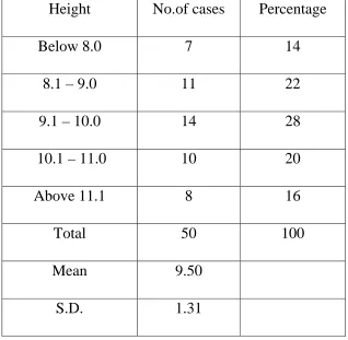
Table – 1
Height of the Pedicle
Height No.of cases Percentage
Below 8.0 7 14
8.1 – 9.0 11 22
9.1 – 10.0 14 28
10.1 – 11.0 10 20
Above 11.1 8 16
Total 50 100
Mean 9.50 S.D. 1.31
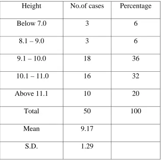
Table – 2
Width of the Pedicle
Height No.of cases Percentage
Below 7.0 3 6
8.1 – 9.0 3 6
9.1 – 10.0 18 36
10.1 – 11.0 16 32
Above 11.1 10 20
Total 50 100
Mean 9.17 S.D. 1.29
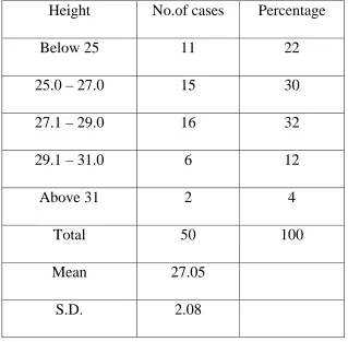
Table – 3
Length of Lateral Mass
Height No.of cases Percentage
Below 25 11 22
25.0 – 27.0 15 30
27.1 – 29.0 16 32
29.1 – 31.0 6 12
Above 31 2 4
Total 50 100
Mean 27.05 S.D. 2.08
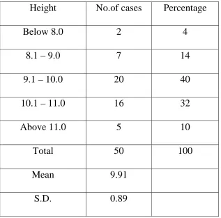
Table – 4
External Height of Lateral Mass
Height No.of cases Percentage
Below 8.0 2 4
8.1 – 9.0 7 14
9.1 – 10.0 20 40
10.1 – 11.0 16 32
Above 11.0 5 10
Total 50 100
Mean 9.91 S.D. 0.89
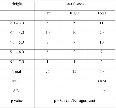
Table – 5
Depth of Vertebral artery groove
Height No.of cases
Left Right Total
2.0 – 3.0 6 5 11
3.1 – 4.0 10 10 20
4.1 – 5.0 3 7 10
5.1 – 6.0 5 2 7
6.1 – 7.0 1 1 2
Total 25 25 50
Mean 3.874
S.D. 1.12
p value p = 0.929 Not significant
Depth of vertebral artery groove in the present study was found to have no significant asymmetry between the right and left sides(p=0.929) with 6 specimens having vertebral artery groove depth > 5mm on the left side, and 3 specimens having measurements > 5mm on right side.
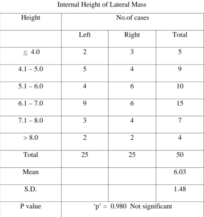
Table – 6
Internal Height of Lateral Mass
Height No.of cases
Left Right Total
< 4.0 2 3 5
4.1 – 5.0 5 4 9
5.1 – 6.0 4 6 10
6.1 – 7.0 9 6 15
7.1 – 8.0 3 4 7
> 8.0 2 2 4
Total 25 25 50
Mean 6.03
S.D. 1.48
P value ‘p’ = 0.980 Not significant
Table – 7
Length of VA Groove
Height No.of cases
Left Right Total
< 5.0 3 3 6
5.1 – 6.0 6 11 17
6.1 – 7.0 8 8 16
7.1 – 8.0 5 2 7
> 8.0 3 1 4
Total 25 25 50 Mean 6.2
S.D. 1.06
‘p’ value ‘p’ = 0.060 Not significant
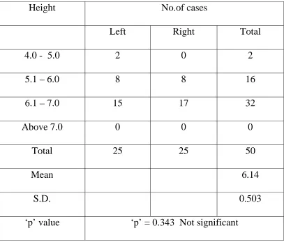
Table – 8
Height of transverse foramen
Height No.of cases
Left Right Total
4.0 - 5.0 2 0 2
5.1 – 6.0 8 8 16
6.1 – 7.0 15 17 32
Above 7.0 0 0 0
Total 25 25 50
Mean 6.14
S.D. 0.503
‘p’ value ‘p’ = 0.343 Not significant
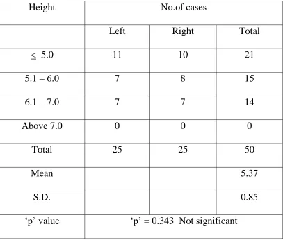
Table – 9
Width of transverse foramen
Height No.of cases
Left Right Total
< 5.0 11 10 21
5.1 – 6.0 7 8 15
6.1 – 7.0 7 7 14
Above 7.0 0 0 0
Total 25 25 50
Mean 5.37
S.D. 0.85
‘p’ value ‘p’ = 0.343 Not significant
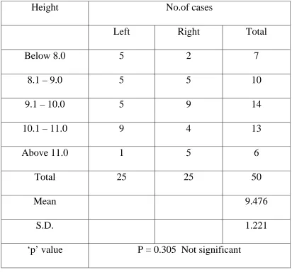
Table – 10
External Height of Lateral Mass (CT)
Height No.of cases
Left Right Total
Below 8.0 5 2 7
8.1 – 9.0 5 5 10
9.1 – 10.0 5 9 14
10.1 – 11.0 9 4 13
Above 11.0 1 5 6
Total 25 25 50
Mean 9.476
S.D. 1.221
‘p’ value P = 0.305 Not significant
Table – 11
Depth of Vertebral artery Groove (CT)
Height No.of cases
Left Right Total
2.0 – 3.0 2 8 10
3.1 – 4.0 9 10 19
4.1 – 5.0 7 4 11
5.1 – 6.0 6 2 8
6.1 – 7.0 1 1 2
Total 25 25 50
Mean 3.814
S.D. 1.063
p value p = 0.009 Significant
Table – 12
Internal Height of Lateral Mass (CT)
Height No.of cases
Left Right Total
< 4.0 5 1 6
4.1 – 5.0 8 4 12
5.1 – 6.0 6 8 14
6.1 – 7.0 4 4 8
7.1 – 8.0 2 2 4
> 8.0 0 6 6
Total 25 25 50
Mean 5.663
S.D. 1.471
P value ‘p’ = 0.005 Significant
The mean internal height of lateral mass was observed to be 5.663 mm with a minimum observation of 2.68 mm and maximum observation 8.5mm. 52% of the specimens had an observation of internal height of lateral mass lying between 4 and 6 mm.
Table – 13
Length of VA Groove (CT)
Height No.of cases
Left Right Total
22 - 24 0 3 3
26.1 – 28.0 5 8 13
28.1 – 30.0 7 1 8
30.1 – 32.0 4 3 7
> 32 1 0 1
Total 25 25 50
Mean 27.271
S.D. 2.600
‘p’ value ‘p’ = 0.032 Significant
Table – 14
Height of transverse foramen (CT)
Height No.of cases
Left Right Total
4.0 - 5.0 7 4 11
5.1 – 6.0 7 7 14
6.1 – 7.0 8 8 16
Above 7.0 3 6 9
Total 25 25 50
Mean 5.958
S.D. 1.093
‘p’ value ‘p’ = 0.467 Not significant
OBSERVATION AND RESULTS
There was a large variation in the dimensions of the 25 dry specimens of the axis vertebrae and in the symmetry of each specimen.
The mean width of the pedicle was 9.17 mm (6.06 – 11.75)and the mean height of the pedicle was 9.5 mm (6.76 – 12.7).
The lateral masses had a mean external height of 9.91 mm (7.9 – 11.9 ) and a mean internal height of 6.03 mm (3.28 – 9.56)and the mean depth of vertebral artery groove was 3.874mm (2.05 – 6.73).
The transverse foramen had a mean height of 6.14 mm (4.4 – 6.8) and a mean width of 5.37 mm (3.8 – 6.9).
The course of the vertebral artery through the lateral mass of C2 was very variable in shape, size, location and symmetry. An abnormal groove or erosion was found on both sides in none of these specimens, on the left side in 6 specimens and on the right side in 3 of the specimens.
In the study of dry bones, abnormal vertebral artery groove was noted in 20% of specimens.
significant asymmetry between the right and left sides for the depth of vertebral artery groove (p=0.929), internal height of lateral mass (p=0.98), length of Vertebral artery groove (p=0.06),the height of transverse foramen (p=0.343) and width of transverse foramen (p=0.343).The ratio of internal height to verterbral artery groove was < 1 in 6 specimens on the left side and 4 specimens on the left side. If this ratio is > 1, favourable circumstances for transarticular screw fixation exist.
CT Morphometery :
asymmetry between right and left sides was not seen for the external height of the lateral mass (p=0.305) and the height of the transverse foramen (p=0.467).
DISCUSSION
This study has focussed on the anatomical features of the vertebra of C2 which are important in the instrumental stabilization of C1 to C2. Variations in the course of the vertebral artery through C2 has been described before in case reports, 6,8 in dried specimens, 3,53 by CT 54and in cadavers.
CONCLUSION
Thinning of the lateral mass and the pedicle of axis vertebra may prevent adequate fixation by posterior transarticular screw placement. The agent responsible for this thinning is the axis groove for the vertebral artery, indicating the increased probability of vertebral artery injury. The range of variation of these and other measured parameters suggest the need to thoroughly evaluate them before operative planning when screw fixation is contemplated. High resolution thin section CT scanning is recommended for this purpose.
Vertebral artery injury can be avoided by improved understanding of the safety limits for transarticular screw fixation through the lateral mass by real time intra operative fluoroscopy control and by avoiding the procedure in anatomically unsuitable cases.
BIBLIOGRAPHY
1. Heggeness MH, Doherty BJ. The trabecular anatomy of the axis.Spine 1993;18:1945-9.
2. Schaffler MB, Alson MD, Heller JG, Garfin SR. Morphology of the dens: a quantitative study. Spine 1992;17:738-43.
3. Taitz C, Arensburg B. Erosion of the foramen transversarium of the axis: anatomical observations. Acta Anat Basel 1989 ;134:12-7.
4. Doherty BJ, Heggeness MH. Quantitative anatomy of the second cervical vertebra. Spine 1995;20:513-7.
5. Xu R, Nadaud MC, Ebraheim NA, Yeasting RA. Morphology of the second cervical vertebra and the posterior projection of the C2 pedicle axis. Spine 1995;20:259-63.
6. Cooper DF. Bone erosion of the cervical vertebrae secondary to tortuosity of the vertebral artery: case report. J Neurosurg
1980;53: 106-8.
7. Taitz C, Arensburg B. Vertebral artery tortuosity with concomitant erosion of the foramen of the transverse process of the axis: possible
clinical implications. Acta Anat Basel 1991;141:104-8.
8. Wickbom GI, Williamson MR. Anomalous foramen transversarium of C2 simulating erosion of bone.
Neuroradiology 1980;19:43-5.
10. Menezes AH,Van Gilder JC:Anomalies of the Craniovertebral junction. In Youmans JR (ed):Neurological surgery. Philadelphia, WB Saunders,1990,pp 1359-1420.
11. Menezes AH:Posterior occipitocervical fixation.Tech neurosurg 1:72-81,1995.
12 White AA 3rd,Panjabi MM:Clinical biomechanics of the Spine.Philadelphia,JB Lippincott,1978.
13. Peter L Williams,Roger Warwick,Mary Dyson,Lawrence Bannister.Osteology of the axial skeleton:Gray’s anatomy37th ed.P 318-319.
14. Neurosurgery:official journal of the congress of neurological surgeons.Rhoton’s anatomy.Oct 2003.Vol 53 P591-592.
15. Bailey DK:The normal cervical spine in infants and children.Radiology 59:712-719,1952.
16. Werne S: Studies in spontaneous atlas dislocation. Acta Orthop Scand Suppl 23:1-150, 1957.
17. White AA III, Panjabi MM : The clinical biomechanics of the occipitoatlantoaxial complex. Orthop Clin orth Am 9:867-878, 1978.
18. Dvorak J, Schneider E, Saldinger P, et al: Biomechanics of the craniocervical region. The alar and transverse ligaments J Orthop Res 6:452-461, 1988.
20. Harris MB,Duval MJ,Davis JA Jr,et al:Anatomical and roentgenographic features of atlanto occipital instability.J spinal Disord 6:5-10,1993.
21. Menezes AH, VanGilder JC, Graf CJ et al: Craniocervical abnormalities. A comprehensive surgical approach J Neurosurg 53:444, 1980.
22. Menezes AH : Transoral approach to the clivus and upper cervical spine. P. 306. In Wilkins RH, Rengachary SS (eds): Neurosurgery Update I. McGraw Hill, New York, 1990.
23. Wolf AL.Initial management of brain and spinal cord injured patients. Emerg Med Serv 18:35-41,1989.
24. Sonntag VK,Hadley MN:Non operative management of cervical spine injuries.Clin Neurosurg 34:630-649,1988.
25. White AA 3rd,Panjabi MM:Clinical Biomechanics of the spine.Philadelphia,Lippincott-Raven,1990.
26. Crawford NR,Hulbert RJ,Choi WG,et al:Differential biomechanical effects of injury and wiring at C1-C2.
27. Paramore CG,Dickman CA,Sonntag VKH:The anatomical suitability of the C1-C2 complex for transarticular screw fixation. J Neurosurg85:221-224,1996.
28. Song GS,Theodore N,Dickman CA,et al.Unilateral posterior atlantoaxial transarticular screw fixation.J Neurosurg 87:850-855,199.
30. Mummaneni PV,Haid RW Jr,Traynelis VC,et al:Posterior cervical fixation using a new polyaxial screw and rod system:Techniques and surgical results.Neurosurg focus 12:2002.
31. Fiore A,Haid RW,Jr,Rodts GE,et al:Atlantal lateral mass screws for posterior spinal reconstruction.Technical note and case series.Neurosurg focus 12:2002.
32. Mummaneni PV,Haid RW,Jr,Fiore A,et al:Posterior fixation options for the C1-C2 complex:Wires,clamps,and screws.Contemp Neurosurg 25:1-8,2003.
33. VanGilder JC, Menezes AH, Dolan KD : The craniovertebral Junction and Its Abnormalities. Futura Publishing Mt. Kisco, NY, 1987.
34. Menezes AH, Van Gilder JC : Abnormalities of the craniovertebral junction. P.1359. In Youmans J ()ed) : Neurological Surgery : 3rd Ed. WB Saunders, Philadelphia, 1990.
35. McRae DL : The significance of abnormalities of the cervical spine. AJR 84:3, 1960.
36. Nicholson JT, Sherk HH : Anomalies of the occipitocervical articulation. J Bone Joint Surg (Am) 50:295, 1968.
37. Tanzier A : Die basilare Impression. Radiol Clin 25:135, 1956. 38. Poppel MH, Jacobson HG, Duff BK : Basilar impression and
39. Pozo JL, Crokard HA, Ransford AO : Basilar impression in ostegenesis imperfecta: a report of 3 cases in one family. J Bone Joint Surg (Br) 66:233, 1984.
40. Schmidt H, Sartor K, Heckl RW : Bone malformations of the craniocervical region. P. 1.In Vinken PS,Bruyn GW (eds) : Handbook of Clinical Neurology. Vol.32, Congenital Malformations of the Spine and the Spinal Cord. North-Holland, Amsterdam, 1978.
41. Sharp J, Purser DW : Spontaneous atlanto-axial dislocation in ankylosing spondylitis and rheumatoid arthritis. Ann Rheum Dis 20:47, 1961.
42. Von Torklus D, Gehle W : The upper cervical spine. Regional anatomy, pathology and traumatology. P.2 In : A Systemic Radiological Atlas and Textbook. Grune & Stratton, Orlando, FL, 1972.
43. Menezes AH,Van Glider JC,Clark CR et al:Odontoid upward migration in rheumatoid arthritis.An analysis of 45 patients with “cranial settling”.J Neurosurg 63:500,1985
44. Smith HP,Challa VR,Alexander E,Jr:Odontoid compression of the brainstem in a patient with rheumatoid arthritis.Case report.J Neurosurg 53:841,1980.
45. Van Gilder JC,Menezes AH:Craniovertebral abnormalities and
their treatment.p1221.In Schmidek HH,Sweet WH(eds):Operative Neurosurgical techniques.Vol.1.Grune and Stratton,Orlando,FL,1982.
47. Santavirta S,Slatis P,Kakaanpaa V et al:Treatment of the cervical spine in rheumatoid arthritis.J Bone Joint Surg(Am)70:658,1988.
48. Mathews JA:Atlantoaxial subluxation in rheumatoid arthritis.Ann Rheum Dis 28:260,1969.
49. Anderson LD,D ‘Alonzo RT:fractures of the odontoid process of the axis. JBone Joint Surg Am 56:1663-1674,1974.
50. Hadley MN,Browner CM,Liu SS,et al:New subtype of acute odontoid fractures(type iia).Neurosurgery 22:67-71,1988.
51. Levine AM,Edwards CC:The management of traumatic spondylolisthesis of the axis.J Bone Joint Surg Am67:217-226,1985.
52. Cooper PR,Cohen A,Rosiello A,Koslow M:Posterior stabilization of cervical spine fractures and subluxations using plates and screws.Neurosurgery 23:300-306,1988.
53. Taitz C,Nathan H,Arensburg B.Anatomical observations of the foramina transversaria.J Neurol Neurosurg Psychiatry 1978;41:170-6.
54. Paramore CG, Dickman CA, Sonntag VKH. The anatomical suitability of the C1-C2 complex for posterior transarticular screw fixation. Proceedings of the Cervical Spine Research Society (abst) 23rd annual meeting, Santa-Fe, 1995:50.
56. Dull ST, Toselli RM. Preoperative oblique axial computed tomographic imaging for C1-C2 transarticular screw fixation: technical note. Neurosurgery 1995;37:150-2.
57. Anderson RE,Shealy CN.Cervical pedicle erosion and rootlet compression caused by a tortuous vertebral artery.Radiology 1970;96:537-8.
58. Ali abou madawi,Guirish solanki,Adrian T.H.Casey,H.Alan Crockard.Variation of the groove for the vertebral artery in the axis vertebra.Implications for instrumentation.J Bone Joint Surg(Br)1997;79B:820-3.
9
7
6
8
10
6
8
10
12
Depth of Vertebral artery Groove (CT)
2
1
4
2
1
0
2
4
6
2.0 – 3.0
3.1 – 4.0
4.1 – 5.0
5.1 – 6.0
6.1 – 7.0
MASTER CHART (CT MORPHOMETRY)
S.
No. Name Age Sex IP No Side
External Height of lateral mass VA Groove Internal Height Pedicle Length Length of VA groove
1 Mani kandan 39 M 1519 L 8.65 4.82 3.83 25.02 6.02
2 R 9.92 4.18 5.74 31.32 6.33
3 Saravanan 30 M 1520 L 10.82 6.01 4.81 36.42 7.2
4 R 9.36 6.03 3.33 27.04 7.54
5 Vel murugan 50 M 1591 L 8.82 4.12 4.7 28.72 5.66
6 R 11.2 5.16 6.04 27.09 5.43
7 Thirupathi 22 M 1594 L 10.92 5.42 5.5 24.58 4.92
8 R 10.04 5.6 4.44 26.82 4.86
9 Fiedel castro 34 M 1671 L 10.45 5.72 4.73 27.62 4.42
10 R 10.29 2.06 8.23 25.61 4.2
11 Dhinesh kumar 19 M 1672 L 11.9 4.4 7.5 29.03 5.92
12 R 8.56 2.05 6.51 24.38 6.02
13 Selvi 37 F 1674 L 9.28 3.62 5.66 28.26 6.36
14 R 9.3 3.32 5.98 27.82 7.02
15 Thirukan 50 M 1675 L 7.15 3.37 3.78 29.03 6.66
16 R 8.82 3.35 5.47 27.8 7.92
17 Baskaran 23 M 1676 L 9.21 5.76 3.45 26.83 5.92
18 R 10.35 2.24 8.11 31.44 5.36
19 Murugan 32 M 1678 L 10.15 3.1 7.05 30.01 5.54
20 R 11.02 2.56 8.46 31.66 5.46
21 Sundaresan 35 M 1681 L 6.71 3.72 2.99 30.72 4.42
22 R 8.83 3.35 5.48 25.41 4.26
23 Pandi 30 M 1683 L 7.72 3.63 4.09 24.86 4.55
24 R 11.04 3.02 8.02 27.09 4.92
25 Ramu 43 M 1729 L 10.48 4.14 6.34 28.06 5.07
26 R 10.22 2.41 7.81 26.67 6.08
27 Podhumani 25 F 1760 L 10.42 3.69 6.73 27.84 7.66
28 R 11.12 2.62 8.5 23.82 7.81
29 Dhana backiyam 33 F 1762 L 10.02 5.07 4.95 27.54 7.82
30 R 9.92 2.72 7.2 24.26 7.98
31 Kali muthu 46 M 1764 L 9.32 3.77 5.55 25.09 4.41
32 R 7.62 3.42 4.2 23.81 6.24
33 Thanga vel 32 M 1763 L 7.51 2.55 4.96 27.09 6.92
34 R 8.84 3.41 5.43 24.26 6.34
35 Subramanian 65 M 1765 L 9.32 3.52 5.8 31.02 6.31
36 R 9.14 4.42 4.72 22.94 6.81
37 Murugan 40 M 1766 L 6.85 4.17 2.68 25.02 6.94
38 R 9.54 3.22 6.32 26.01 6.56
39 Karuppaian 55 M 1767 L 10.62 5.02 5.6 27.56 6.42
40 R 11.81 3.72 8.09 28.62 6.33
41 Parakath Ali 55 M 1834 L 10.41 4.02 6.39 29.52 6.77
42 R 9.16 4.12 5.04 24.06 7.91
43 Kasimayan 43 M 1835 L 8.66 2.52 6.14 30.01 5.14
44 R 7.69 3.12 4.57 24.02 5.23
45 Murugan 25 M 1913 L 8.92 3.69 5.23 26.02 4.96
46 R 8.88 3.02 5.86 25.02 5.11
47 Nagaraj 16 M 1914 L 8.96 4.12 4.84 26.82 5.17
48 R 9.36 4.01 5.35 27.55 5.07
49 Vellaiyangiri 38 F 2018 L 9.16 5.02 4.14 28.66 4.92