Ames Laboratory ISC Technical Reports Ames Laboratory
7-25-1951
Some calorimetric studies of the metals and
chlorides of cerium and neodymium
F. H. Spedding
Iowa State CollegeCarl F. Miller
Iowa State CollegeFollow this and additional works at:http://lib.dr.iastate.edu/ameslab_iscreports Part of theCeramic Materials Commons, and theMetallurgy Commons
This Report is brought to you for free and open access by the Ames Laboratory at Iowa State University Digital Repository. It has been accepted for inclusion in Ames Laboratory ISC Technical Reports by an authorized administrator of Iowa State University Digital Repository. For more information, please contactdigirep@iastate.edu.
Recommended Citation
Spedding, F. H. and Miller, Carl F., "Some calorimetric studies of the metals and chlorides of cerium and neodymium" (1951).Ames Laboratory ISC Technical Reports. 41.
Some calorimetric studies of the metals and chlorides of cerium and
neodymium
Abstract
The following thermal data have been measured f or some of t he compounds and metals of cerium and neodymiumz (1) the heats of solution and dilution of the anhydr ous chlorides i n aqueous solution; (2) the changes in heat capacities of solution and dilution of the anhydrous chlorides in aqueous solution; (3) the heats of solution of the anhydrous chlorides and metals in aqueous hydrochloric acid; (4) the heats of solution of the hydrated chlorides in aqueous solution; ( 5) the heats of precipitation of the oxalates in aqueous oxalic acid solution; and (6) the heat capacity of neodymium metal in the temperature range of 0° to 250°C. In addition, the heats of solution and dilution of potassium chloride and oxalic acid hydrate in aqueous solution, and the heat capacity of tantalum metal from 0°C to 425°C have been measured.
Keywords Ames Laboratory
Disciplines
Ceramic Materials | Engineering | Materials Science and Engineering | Metallurgy
l
..
'
~
o
W()v
sc.
AI-rs
c.-1~1
ISC-167
By
F. H. Spedding
Car 1 F. Miller
July 25, 1951
Ames Laboratory
ATOMIC ENERGY COMMISSION
·
.
METALLURGY AND CERAMICS Reproduced direct from copy
as submitted to this office. PRINTED IN USA PRICE 40 CENTS Available from the Office of Technical Services
Department of Commerce Washington 25, D. C. Work performed under Contract No. W-7405-eng-82.
3
TABLE OF CONTENTS
Page
AB.S'rF~.ACT •••••••••••••••••••••••••••••••••• • •• • • • • • • • • • • • • • • • • o • • 4 INTRODUCTION ••••••••••••••••••••••••••••••••••••••••••••••ooooeo CAlORIMETRY OF -..OLUTIONS • • • o • • • e • • • • • • • • • • • • • • • • • • • • • • • • • o • • • • • e
Introd.11ction ••••••••••••••••.•••••••••••••••••••••••••••••• Theory ••••••••••••••••••••••••••••••••••••••••••.•••••• o • o • General Methods ···••••••••••••••••••••••••••••••••••••••••• Experimental•••••••••••••••••••••••••••••••••••••••••oo•••• Preparation of materials •••••••••••••••••••••••••••••• A:pparatus • • • • • • • • • • • • • • • • • • • • • • • • • • • •• • • • • • • • • • • • • • • • 0 Tree.trnent of data ••••••••••••••••••••••••••••••••••••• P.e sul ts •••••••••••••••••••••••••••••••••••••••••• o • • • o Discv.ssion ••••••••••••••••••••.••••••••••••.•••••••••••••• o THERII:ODYNAMICf, OF CHF.MICAL RE:"CTimrs ••••••••••••••••••••••••••••
IntrOO.uction ••••••••••••••••••••••••••••••••••••.••••• o • • • o Heats of Formation ••••••••••••••••••••••••••••.•••••••• o•••
~J.iliydrous chlorides ••••••••••••••••••••••••••••••• oooe Hydrated chlarjdes ••••••••.•••••••••••••••••••••••••• o
Ions ••••••••••••••••.•••••••••••.•.•.•••••••••••••••• o Entropy and P'ree F~ergy •.•••••••••••••••.•••••••••••••• e • •• Heat of formation oi the oxalates ••••••••••••••••••••• Heat of solution of oxalic acid ••••••••••••••••••••••• Heat of precipitation of oxalhtes •••••••••••••••••••
o.
Results ••••••••••••••.•.•••••••••••••••.•••••.•••••• o •• • o ~ •Dis cuss ion ••••••••••••••••••••••••••••••••••••••••••••••. o • • HEAT C~~ACITY OF SOLIDS •••••••.•••••.•••.•••••••••••••••.•••• o • • Intrcxluction ••••••••••••.•••••••••••••.•••••••••••••• a • • • • • Theory ••••••••••••••••••••••••••. • •••••••••••••••••••••••••• M.ethcC.s of IV!easurement •••••••••••••••••••••••••••••••••••• o Experimental ••••••••••••••••••••••.••••••.••.•••••••.•••• o o Preparation of materials•••••••••••••••••••••••••••••o Apparatus ••••••••••••••••••••••••••••••••••••••• o . o o • • Results ••••••••••••••••••••••••••.•.•••••••.•••••••••• Discussion ••••••••••••••.•••••.•••••••••.••••••••••••••• o o. ~3lJ~Y AND CONCLUSIONS •• ~~~ ••••••• ., o . . . ... & •
Sununa.ry • • • • • • • • • • • • • ., ~~~ o • • • Conclusions and. Comments ••
L ·rTE.~A TlJRE CITED •••••••••••••••• " •••••••••••••••••• •••••••••.••• A C~OWL.EJ)GEME;NTS ••••••••••••••••••• o . . . .. . . .. . . . .. .. . . .,
4
SOME CALORIME1RIC STUDIES OF THE
METAlS AND CHLORIDES OF CERIUM AND NEODYMIUM1 by
F. H.
Spedding and CarlF.
MillerFrom the Department of Chemistry Iowa State College
ABSTRACT
The following thermal data have been measured for some of the
compounds and metals of cerium and neodymiumz (1) the heats of solu -tion and dilution of the anhydrous chlorides in aqueous solution;
(2) the changes in heat capacities of solution and dilution of the
anhydrous chlorides in aqueous solution~ (3) the heats of solution of
the anhydrous chlorides and metals in aqueous hydrochloric acid~ (4)
the heats of solution of the hydrated chlorides in aqueous solution; (5) the heats of precipitation of the oxalates in aqueous oxalic acid
solution; and (6) the heat capacity of neodymium metal in the tempera~ ture range of oo to 250°C. In addition, the heats of solution and
dilution of potassium chloride and oxalic acid hydrate in aqueous
solution, and the heat capacity of tantalum metal from 0°Ce to 425°Co
have been measured.
From the data on the heats of solution and ilution, the following thermodynamic quantities have been determined& (1) t.he relative
apparent molal and relative partial molal heat contents of solutions
of the chlorides of cerium and neodymium~ {2) the relative apparent
molal and relative partial molal heat capacities of solutions of the
chlorides of cerium and neodymium; (3) the heats of formation of the anhydrous chlorides of cerium and neodymium; (4) the heats of hydration
and of formation of hydrated chlorides of cerium and neodymium» (5)
the heats of formation of the hydrated oxalates of cerium and neodymium;
and (6) the heats of formation of the ions of cerium and neodymium. Revised values for the heat of solution at infinite dilution of
potassium chloride and the heat of formation of oxalic acid hydrate
have been presented. With the aid of data in the literature~ the
entropies, entropies of formation9 and free energies of formation of the above chemical substances as well as the standard electrode
5 ISC-167
potentials of the metals of cerium
and
neodymium have been calculated.The heats of solution and dilution were measured by the use of an isothermal claorimeter kept in a bath thermostatically controlled at 25.00
±
o.Ol°C; the temperature of the calorimeter was measured bythe use of a transposed-bridge thermometer to an accuracy of
30
micro-degrees. The heat capacities of tantalum and neodymium metals were measured by the use of ice calorimeters similar to those de~cribedqy
Ginnings and Corruccini 1 and by Ginnings, Douglas, and Ball • The
accuracy of the measurements of the heat of solution calorimeter and its contents and of the measurements of all the heats of solution and
dilution was within 0.1 per cent. The accuracy of the measurements of the heat capacities of solids by use of the ice calorimeters was about one per cent.
The heats of solution of anhydrous neodymium chloride were found to be greater than those of anhydrous cerium chloride; this phenomenon is ma~nly due to the formation of more stable dipole bonds between the neodymium ion and the surrounding water molecules since the lattice energies of the two anhydrous chlorides should be of the same order of magnitude. From these considerations and the fact that the ionic radius of the rare earths decreases with increasing atomic number, ~he heats of hydration of the rare earth ions should increase with atomic number.
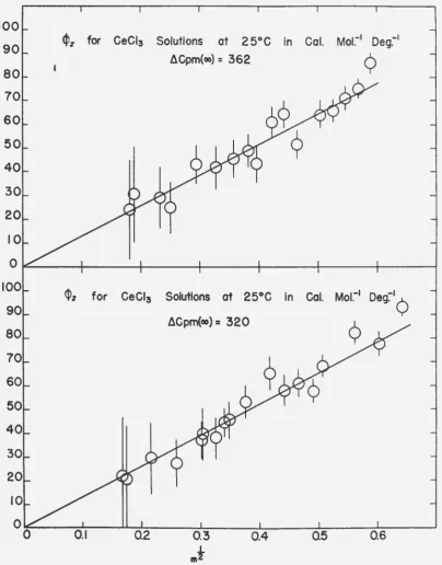
An extrapolation of the data on the heats of solution and dilution of the two chlorides to infinite dilution showed agreement with the simplified Debye-Huckel theory. For solutions more concentrated than 0.05 molal, the relative apparent molal and partial molal heat contents of cerium chloride were found to be greater than those of neodymium chloride. A tentative explanation is that, in addition to the heat effects attributed to the difference in the parameter of closest
approach of the ions, a second coordination number may become possible as the rare earth ion becomes larger with decreasing atomic number. Moreover, an equilibrium exists between the two hydrated ion-species: a shift in this equilibrium, as the concentration increases, is
associated with an increase in the observed heat contents. Additional data will be required before any definite conclusions can be dra~n.
lGinnings, D.
c.,
and R. J. Corruccini, J. Research Natl. Bur. Stds.,2§,
583-591 (1947).6
ISC-167· The heats of solution of the anhydrous chlorides of cerium and of neodymium in hydrochloric acid were found to be less than they were in water. For solutions of the same concentration of electrolytes~ the heats of solution of neodymium chloride were reduced more than those of cerium chloride. Further experimental evidence will be required to show if t~is behavior varies with ionic radius for the rare earths and whether it is due to association.
The measurements of thermal properties of cerium and neodymium and some of their compounds, presented in this thesis, are of importance in furnishing data which are useful in applying the laws of thermo
-dynamics to these substancesa The data are part of an extensive pro-gram for the accumulation of accurate data on the physicochemical properties of all the rare earth metals and salts in progress at the Ames Laboratory. Such data will furnish the information by means of which the present theories of solutions and solids can be examined in greater detail than has heretofore been possible.
INTRODUCTION
The field of thermodynamics has reached its present high state of development mainly through the basic contribtuions of Jo Willard Gibbs
(1), who established it on a firm mathematical basis, and of
qe
No Lewis and M. Randall (2), who clearly demonstrated the application ofthe laws of thermodynamics to chemical systems. Since then thermo~ dynamics have been widely applied as a tool to support, extend, or revise the theories which attempt to describe chemical behavior.
Further extension of these theories requires additional accurate thermal experimental data.
Among the more notable new theories which arose was the inter-ionic attrarr~ion theory for electrolytic solutions as developed by Debye and n~~Kel; Onsager and Fuoss; Ao A. Noyes; and many others. Harned and Owen (3) have recently presented a critical review of the
theories of electrolytic solutions and the data on which they are based. They show that, while modern solution theory accounts well for the properties of dilute electrolytes, a great deal of new experi-mental data will be required to extend its application to more
con-centrated solutions. Two kinds of assumptions are involved in the
analytical expressions of the theory. The first kind is associated with the formulation of the general equations; for example» it is assumed that complete ionization of the salt occurs and that the dielectric constant is unaffected by the ions at all concentrations. The second includes the mathematical approximations used in solving the equations.
7 ISC-167 this assumption is not valid for a large number of electrolytes except over a limited concentration range. Association, changes in hydration
of the ions, and compound formation could be expected to exert more and more influence on the properties of the electrolyte as the charge
density of the medium increases. These factors would not only cause a shift in the ionic distribution but would also alter the forces
acting between the ions. It is believed that all of the phenomena
mentioned above involve heat effects; therefore the partial molal heat contents and heat capacities of the solutions should be sensitive to such deviations from the ideal ionic solution.
The more simplified form of the theory gives an expression for the
mean activity coefficient of the two ions in solution, providing tho main assumptions made in deriving the theory hold over the c oncentra-tion ranges investigated. The first and second derivatives of this expression with respect to temperature give the partial molal heat content and the partial molal heat capacity, respectively, of the
electrolyte in solution. The derivatives directly relate the two thermal properties of the ions to the theoretical equations. The solving of the
equation for concentrated solutions does not allow the mathematical
simplifications which are premissable for the extremely dilute solutions.
The experimental values of the thermal properties of electrolytes are
very sensitive to deviations from the simplifying assumptions made in deriving the theory; therefore., a digression of the experimental values from the predicted ones sho~ud prove very helpful in determining at what concentrations the simplifying assumptions are no longer sufficient to predict these values.
In most of the theoretical equations which give the thermodynamic
properties of the ions in solution, the charge on the ion enters as
a square or higher power of the chargeo Therefore, a deviation from complete ionization would manifest itself a great deal more for an ion of charge three than for one of lower charge. In addition, the
more highly charged ions tend to associate with negative ions; to
hydrolyze to a greater extent; and generally to undergo a higher degree
of solvation. The resulting heat gffects for a trivalent ion would appear at a lower concentration than similar effects for an ion of smaller charge. The rare earth salts are known to be strong electro -lytes which would be ideally suited for making studies of the 3-1 valence type. Solutions of the rare earth chlorides, if properly prepared are not hydrolyzed, and measurements of their activity coefficients (4)
tl
indicate that they obey the Debye-Huckel theory at infinite dilution. If this holds true for other properties, the extension of the measure-ments of all the properties to higher concentrations should throw light
8
While the general chemical properties of the rare earths have been
known for some time it has been very difficult to obtain pure compounds
of most of them because of their very similar chemical properties.
However, the ion-exchange method of separation as developed at the Ames
Laboratory (5) over the past few years has produced many very pure
rare earth salts in sufficient quantity for extensive experimentationo
+he rare earth elements possess atomic structures with three
elec-trons in the valence shell; since the valence electrons determine the
chemical properties of an element~ the group furnishes a unique series
of salts and ions. As the nuclear charge increases, from one element
to the next3 the additional electron falls into the 4f orbitale The
increased charge on the nucleus exerts, in turn~ a greater force on
the electrons in the inner shells thereby pulling them inwards and
shrinking the ionic radiuse
The 4f electrons give rise to sharp energy states as evidenced
b.1
their absorption spectra. In the solid state the neighboring ions set
up electric fields which penetrate the inner shells to cause Stark
splitting of the energy levels; further splitting is found when mag~
netic fields are imposede The observed splitting of these levels aids
in determining the symmetry and strength of the electric fields set up
in the solid by neighboring atomso However9 the
4f
electrons have very little or no effect on the chemical properties of the rare earthionso
All ions of the rare earth elements have a tri~positive charge in
their normal state in aqueous solutions; they would9 therefore~ be
expected to act alike except for differences which can be related to
their sizeo Ions with a higher charge are more highly hydrated since
their highly intense electric fields tend to tie up the water dipoles
more strongly. Smaller ions of the same charge present a relatively
larger surface charge density and may orient the surrounding water
dipoles to such an extent that the resulting hydrated ion is largero
As a result of the extraordinary increase in size of the small ions9
their transport velocities will be decreased due to the fact that they
will meet more resistance from other water molecules as they travel
through the solution than they would if hydration did not occur o The
heats of solution of the salts will be increased because more and
stronger ion-dipole bonds are formed with the immediate surrounding
solvent water molecules and dipole-dipole bonds between the solvent
molecules further away are formed when the salt is dissolvedo ·Since
the charge on the ion is a constant factor for all the rare earth
elements and the ionic radius of these elements in crystals is known
to decrease with atomic number (6)9 the properties mentioned above9
9 ISC-167
structural details of the hydrated ions. The properties of these ions
and salts should show a regular progression related to the gradual
change in the radius of the hydrated ion from one rare earth element
to another, and other thermal properties of tthi.s series of elements,
besides the heats of solution of their saltfr~ ~ould be expected to
exhibit such a regular change. { ·
I
'
Although some measurements of the thermal properties of the rare
earth metals and compounds have been made, the information is rather
limited in scope and some of the data were obtained from impure compounds.
The present thesis, on some of the thermal properties of cerium and
neodymium, includes thermal properties of the 3-1 type electrolyte as
derived from the appropriate measured heat quantities. The thermal data were obtained in such a manner that the powerfUl methods of
thermodynamics could be applied to these substances. CALORIMETRY OF SOLUTIONS
Introduction
When a crystalline salt is dissolved in water, the crystal lattice
is destroyed; the ions are removed from their positions in the crystal
lattice; they are separated to relatively large distances and are
hydrated. 5ince the heats of solution are small compared to the large lattice energies, the hea of hydration of the two ions is also large
and nearly the same as the lattice energy of the ions in the crystal.
Energy is absor ed in the process of separating the ions and, i f the
solution process is not of'fset by solvent reaction with the electrolyte~
the heat absorbed will be about he same as tha required to melt the
crystal; it is exactly equal to the heat of the fusion when the crystal
is dissolved to give a. ideal solution. The fact that the lattice
a d hydration energie"' are uearly equal means that the water dipoles neutralize the electric f·elds of the ions o about the same extent
as the two i ns neutralize each other in the crystal lattice. If the
negative ion is highly polarized in the crystal and if the cation
forms very stable solvates, that is, if it ties up the water dipoles
very strongly, the heat of solution will be larger and heat will be
absorbed or evolved depending on which process involves the greater
energy. It is to be expected that the water molecules would be more
easily polarized than a halogen ion by a higb.ly charged cation; it.
follows that the heat evolved would increase with an increase in the
size of the solvated cation. Born(7) indicates how the energy of' hydration may b calculated if he hydrated ions ~e considered
spheres. However, since the value of the diele tr ·.c constant of the
10 ISC=l67
is to calculate the lattice energy of the crystal (8) and to subtract it from the heat of solution.
According to the Deqye-H~ckel theory~ the energy required to
dilute or separate the ions in solution is equal to the work required
to separate the charges in a solvent of a given dielectric constante Mathel!latically, it is the difference in energy required to 11charge up"
the ionic atmosphere from its value at the initial concentration to its value at the final concentrationo
there is only one report in the literature on the heat of dilution of a ~-1 electrolyte
(9);
and there are no reported data on the heat capacities of 3-1 electrolytes.Theory
The first law of thermodynamics states that if a quantity of heat~
Rg,
is added to a system it causes a resultant change in the energycontent of the system, dE, plus any work~ ~~ done by the systemo In
chemical systems of the type under discussion9 ~, is restricted to
pressure-volume work in which
(1) DW
=
PdVHence
(2) DQ
=
dE ~ PdVThe heat content function is defined as
(3)
whose total differential,
(4)
dH
=(~H)
dT
> (
~!!)
dF
lJT p ~p T
is exact, meaning that
( 5) ~2H
-
•2~~)~
-~T ~p
Differentiation of Equation (3) gives
(6) dH : dE + PdV + VdP
11 ISC-167
( 7) D Q
=
dH - VdPa constant pressure
(8) DQ ·- dH
and for a macroscopic process for a pure substance
(9) Q::
4H
However, for a system f several compone ts,
1!
w:ill be a functionalso of he q ntities of the various materials pres n , or
(10)
dH
=
(~
H,
,
d
T
~
(
..d.Ji
\
dP
4oL
f_'CH\d
n1
{)Tj P,ni
\.dP)
T,ni i \:~ni) P,T,njin which ni is the amount, usually expressed in moles, of
en present in the syst-m. The partial molal derivative,
which is esi~1atP-d as Hi, is the partial molal h at con·ent of each
of the com nents. The-ratter quantity is of special interest for the
interpreta ion of the data to be presented. At constant pre sure and
tempel a ture, Equation Jl-0) _becomes (11) dH ::
~
i
H1dniIntegration f th above equation gives
(J2) H -
2
i
H
1nFor a wo-com onen system of a sal in water, Equation (12) becomes
(13) H
=
n1H1t.
n2H2in which ~ is the num er of moles of water present a d ~~ is the number of moles of salt present.
~inc ~a· measuremen s give differences in the heat con en when
any sys te changes from the initial to the final tat , , it i.s cus oma y
to choo .. e a co venient reference s ate :from which to measure differences in the heat content. In the case of electrolytic solutions, the refer
-ence state for the solvent i.s pure water and the eforence state or
the lectrolyt is at infin·te dilution: these referenc sta es are esignated as ~ for the water and as ~ for the e ectrolyte. The h at c n ent of the solution, relative to th6 ch se reference states, is .hen giv ~ by the equation
12 ISC-167
in which H is the heat content of the solution and L is the relative heat content of the solution. If Equation (13) is substituted for
fi,
the relative heat content will be
- 0 - ~ -
-(15) L : nl(H1 - H1) ~ n2(H2 - H2) : n1L1
+
n2L2in which
Ll
and L2 are the relative partial molal heat contents of the water and the electrolyte, respectively. ·According to Lewis and Randall (2), if
M
moles of salt are dissolved in 1000 grams (55o506 moles) of water to give a solution of molality,m,
the total heat given out or absorbed per mole~ is called the totalor integral heat of solution; if _!!m moles of salt are added to a solution of molality
m
to give a solution of molality m ~ dm, the total change in heat content per mole is the partial or differential heat of solutionoII
For many of the 1-1 and 1-2 salts which obey the Deqye-Huckel laws for dilute solutions (10) it has been found that a quantity defined as the apparent molal heat content, ~' is a linear function of the square root of !he ionic strength through a greater range of concentrations
than is ,!.. The apparent molal heat content~
4
is defined qy the equation0
--(16) H : niii1
+
n2H2=
n1H1~ n2~
which requires that
(17)
In the reference state
(18)
so that
(19) L : H - H0
=
n1Hf .f. n#h~
.
n1H~ -
n2¢h:
n2
~ - ~~) :n-;A
in which~ is the relative apparent molal heat content of the electrolyteo
For a reaction of the type
13
ISC-167(20)
in which H2{s) is the heat content of the solid salt. Since the defini-tion of the reference states requires that
Hf
be equal to Hf, the above-
-equation can be restated b.y adding and subtracting ~ and b.y employing equation (17) in the form
(21) ~It : m(¢h - ~h)
-
m(H2\S) -H2)
: znt
1 - mL2(s)in which -L 2(s) is the heat of solution of the salt at infinite dilution. Differentiation of Equation (21) with respect to~ gives
(22) d AH/dm : f)1 ~ m (d¢r/dm) - L2(s)
However, with the aid of Equation
(15)
and(20),
Equation(21)
canb
e
rewritten as
(23) 6H
=
55.50611+
1rJ.
2 - mL~(s)Differentiation of Equation
(23)
with respect to ~ gives(24) d AH/dm
=
1
2 - L2(s}subtracting Equation
(24)
from(23)
gives(25)
'L
2 :,0
1+
m(d~r/dm)
=
;-i
1~
tmi(d~r/dmi)
Equations (J5) and (19) show that
(26)
if
L2
is substituted into Equation (2~), ~in terms of¢
1
is(27)
1
1=
-tm
31
2/55.506(d¢1,/dm2 )The fundamental equations relating the total heat capacity, .QJ?, of a solution of two components to the partial molal capacities, ~PI and Cp2, of each of the components, or to the molal heat capacity
14 ISC-167
the solute are given
qy
(28) Cp
=
n1cp1 ~ n2cp2=
~cp£ ~ n2¢cpwhere ~p~ is equal to P~p· For the heat capacity of a solution relative
to its reference states, Harned and Owen (3) employ the symbol~ which
is Clefined as
( ) 29 J : o- - ~ ( - ~
Cp- Cp - n1 (cp1 - Cp1)
+
n2 Cp2 - Cp2;: n2(¢cp -
¢~p)
:r2¢J
in which ~ is the relative apparent molal heat capacity of the solute.
-The relative partial molal heat capacities, ~l~ and~' are defined
ey
the equations
(30) and
(31)
from which
(32)
Fer a reaction of the type,
mCeC1
3
(s) ~ 55.506H20=
mCeC13
•55.506H20the change in heat capacity is
(33) b..Cp
=
55.506cpf+
n¢cp - MCp2(s) - 55.506cpf: m{¢ cp - Cp2(s).
It can be shown,
qy
a mathematical treatment exactly analogous tothat used for the partial molal heat contents, that
(34) Cp2 : ¢cp
+
pt(d¢c/dmt)and
15
ISC-167
and
(36)
J
1=
Cp1 -cPr
:
-tm3/
2
/55
.
506(
d~
/d~-)
The relative apparent molal heat capacity ~J' can be determined from a
series of values of~QE for the given reaction at different molalities
by defining ~'-'PM as
(37) CPM : Cp/m : ~cp - Cp2(s)
and
(38)
Cp~
=
¢~P
-
cr
2
(s)at
m
orm
t
=
o.
Since from Equation (30)
(39) Cl)q -
c~
-J_2 can be directly determined through use of Equatio11 (35) while _QE ~
and Cp2 can be determined only if Cp2(s) is known.
For the present work, a development of the complete interionic theory will be unnecessary for the following reasons:
(1) The presentation of t.'l1e theory by Harned and Owen (3) is entirely adequate and can hardly be improved upon at the pres nt time.
(2) This work is concerned with the question of whether or not
3-l electrolytes approach the limiting values of the slopes calculated
from the theory for these electrolytes. Only after data for many other 3-1 type electrolytes and 3-2 type electrolytes have been obtained
a.nd carefully examined, will it be possible to give a better theoretical explanation for the deviations of the observed data from those given by the present theoretical equations.
(3) Many data necessary for .alculating the desired coefficients
at more than infinite dilution are not yet available. An example is the
temperature coefficient of expansion of solutions of the rare earth chlorides.
"
16
ISC-167
can be assumed to be at any point in the solution, but there is a bigher
probability that those of opposite charge will be nearer each other with one tending to surround the other. It is assumed that the work required
to pull the oppositely charged ions apart in performing a dilution is the cause of deviations from the laws of the perfect solutiono The
ionic atmospheres are assumed to have spherical symmetry so that the
potential due to an ion and its surrounding atmosphere is a funct~(~f
the distance from the ion only; the potential is represented b,y r • For a medium containing electrical charges subject only to forces
which vary inversely as the square of the distances, the relation
between the charge density, ~~ and the potential is given» in general, by Poisson's equation
(40)
'V
2~(r)
= _
41fp
/Din which~ is the dielectric constant of the medium. The probability of a given number of charges being present in a potential region where
~ {r) is the potential, considering the thermal motion of the ions, is
taken as that given by the Maxwell-Boltzmann distribution
(41)
P(n) : n exp (-'fJ(r) Ze/kT)in which E is the number of ions per cubic centimeter of the solution
as a whole. The charge density of the region is
(42)
f
=
't_
niZie exp(-~(r)Zie/kT)
i=lin which Zie is the charge on an ion. The quantity, WWZie/kT ~ is
assumed to be small so that
(4.3) exp(-tiJ(r)Zie/kT) ~ 1 ~ o/(r)Zie/kT
if higher terms are neglectedo Substituting Equation (4.3) into Equation (42) gives
(44)
f
=
~
niZie(l - 'J'(r)Zie/kT)Electroneutrality of the solution as a whole requires that
(45)
~
niZ.;e=
0i=l ...
hence
..
and
147) (41\ e /DkT) 2
if
(48)
17
2 n.Z. J. J.
The general soluticn of Equation (47) is
(49) "'(r) : (A/r)e-Kr-+ (B/r)eKr
ISC-167
However, ~ must be zero for 1;
=
dJ , therefore it follows that ] must be zero, and that(50) ~(r)
=
(A/r)e-Kris the only acceptable sol tion. The potential of the ion without its·
atmosphere is
(51)
so that if Equation (50) is written as
(52) ~(r)
=
A/r -(A/r) (1-
e-Kr)the constant~· must be Zie/D, and the second term must be the potential
attributed to the ionic atmosphere. Since the ion carries its charge with it the only work of dilution is the lect.ri.cal work required to
change the ionic atmosphere. Therefore, (53)
is approximately the potential of the atmosphere, and the electrical work required to charge an ion in the presence of the potential o/'(r) is
(54)
D AF. J.=
*
-The electrical work of dilution is assoc:i.ated with the fr e energy change of dilution by the thermodynamics equations which follow. These are:
(55) AF
=
F -
F0 :: 7lRTln(m0x:l)/m,:t lr±18 ISC-167
or
(56) lnCf
1:
= -
1
Z~e~/2DkT
])in which
_l!_
is the mean activity coefficient of the electrolyte in solution. The above relation can be written more correctly for the very dilute solution as(57)
where
(58)
and
(59)
s
=
12.
f
v
i=lFor a 3-1 type electrolyte, M,
=
6m , so thatI 1
(60) ln{f
J:
=
-
Sf(l2d<f1)2gives the limiting equation for the mean activity coefficientso
The variation of the above coefficients with temperature is derived in the following manner from thermodynamic relations;
(61)
and
. (62)"
r(!-~
)/T
lp:
-but
(63)
hence
(64) (ii-jjll)jT2 :
L;T
2 : -1Rf
d~lr;l:
J
..
19
ISC
-1
67
and
(65)
!"-
}~
J
-p
But
(
66
)
so that
'l'he above equ· tions define the limiting slopes in the usuaJ way. An
~amina.tion of Equation (59) .shows that the equations for
1
and forCp - Cp"CJ become increasingly complex when the indicated di
fferentia-tions arG rfcrmed. The values for the slopes ~~, and S have been
-~ ...Q.E
calculated y Harned and Owen '3) and will be given in appropriate
; laces n h:i s t:hes·· s as n~ecl f' -r them arises.
General Methods
The meaf,1 e _ nt of quanti ties of heat by any methcd is termed calorimetry. The mea:"'ll"ements req u · re no knowledge of he 1.U. tirnate
nature of heat; in fact, t e t<>rm "quanti y of heat11 was used when heat was still regarded as a 1'1uid.
The instrument used t o measure q antitios of h-::~i~ is called a
.£Ja.lorimeter; there are tw kinds o.f calorimeter ciApendi.ng on the
thermal process utilized to measure the quantity o.f h&at. 'l'he first
kind is the latent heat calorimeter; its operation depends upon the
c..~ange of tate of some. s!tbstance. placed in the c~J1orimetor. Tho ice
calorimeter is an example of this kin of calorimeter, aDd i~ described
in detail in a following section on specific heats of ::>olids. The
amount of heat added to the calor:imeLer is det"''~"m!.ned from a knowle ge
of the latent heat of fusion o.f ic and the amou.nt of it that c anges
state during the course of the re ction takjng tllB.c:e.
The second kind is cal ed the t errnomctri c.9lo:rime ter; its
20 ISC-167
from observation of the temperature changeso In this kind of calori-meter the thermometer is the instrument of prime importanceo Regnault
built one of the first calorimeters of this kind in
1840;
he determined the amount of heat added to a calorimeter, containing water~ by measuring the temperature rise of calorimeter and water when a warm body wasintroduced into the water. ·The heat capacity of the calorimeter was determined by adding warm water to the water in the calorimeter and noting the initial and final temperatures; this procedure is known as Regnaul t' s method of mixtures. Dulong and Petit used what is now called
the method of cooling to estimate heat quantities; they compared the
time for different substances of the same size and shape to cool through the same temperature range when exposed to the same surroundings.
Regnault, however, pointed out that the method of cooling was not
suitable for measuring heat capacities of solids while it could be used for liquids. Detailed descriptions of the early models of the above mentioned calorimeters are given by Preston (11) and by Worthing and Holliday (12).
The science of calorimetry centers about the invention of tempera-ture-measuring devices and methods of operation that will lead to a more accurate measurement of the temperature and to a better estimate of corrections involving the exchange of heat between substanceso The detailed attention given to these problems by many scientists is evi-denced by the improvement of calorimetric data in the literature over
a period of timeo
The requirements of modern calorimeters~ including their design and operation, are so fully covered by White (13) and by Swietoslawski
(14) that only a brief survey of the general types of the thermometric calorimeters will be necessary in this thesis. Among the best of the calorimeters designed for studies of electrolytes are the models
developed by Lang and his coworkers (15, 16, 17), and by Gucker and his associates
(18)o
The present-day calorimeters which emplqy the use of temperature measurement to obtain the estimation of heat quantities are of three
types: (1) the thermally insulated~jacker model, (2) the adiabatic type, and (3) the isothermally-jacketed calorimeter. A great deal of the work with oxygen-bomb combustion calorimeters is done with the insulated-jacket calorimeter. The quantity of heat produced is usually large; when calibrations are done by the use of standard materials the heat measurements are fairly accurate, especially if the heat leakage is properly taken into accounto The adiabatic calorimeter is best adapted for measuring small quantities of heato Its main advantage is that the heat exchanges with the surroundings are negligible ~~d
21 ISC-167
strictly adiabatic conditions between the calorimeter and its
surround-ings when large quantities of heat arc evolved or absorbed by rapid
processes. Of the three types mentioned above, the adiabatic calori-meters are necessarily more complicated in design and construction
because additional mechanical means have to be employed to heat or
cool a bath in order to maintain temperature equality between the
bath and the calorimeter. The isothermally-jacketed calorimeter is well suited for the measurements of large amounts of heat produced in a rapid process as well as those of longer duration. It is not, when properly constructed and operated, inferior to the adiabatic cal ori-meter (19). However, tl1e heat leakage must be accurately'accounted for and the calculation of the corrections is a tedious task. The advantages of the isothermally-jacketed calorimeter in the present work
are: (1) it is more simple in design and construction tl:ian ·an adiabatic calorimeter of equal precision; (2) it can be operated
br
a minimum amount of labor and personnel; (J) it is best suited to the given labora-tory environment; and (4) it is .. to be used for measuring fairly large quantities of heat developed by rapid chemical reactions.Exper:i.mental
Preparation of materials
The source materials for the anhydrous cercus c..l-J.loride were c.p. hydrated cercus chloride a.11d standard ceri':"! ammonium nitrate procured
from the G. Frederick Smith Company. The analyses of the above
chemi-cals as well as those of all other source materials are given in Table
1. The hydrated cercus chloride gave a slightly turbid solution when
it was dissolved in dilute hydrochloric acid and a small amount of
gelatinous precipitate formed when the solution was boiled with
concen-trated acid. The solution was diluted and ~1e precipitate filtered out. A second boiling produced no further precipitate; the process of
boiling the solution to a syrup in concentrated acid, diluting, and
filtering lvas ep ated two more timss be"ore the solution was boiled
in concentrated acid until e emperature reached 130 C. and the
cercus chloride all wed to crystallize. The hydra"ted crystals were
then placed in a long pyrex drying-· ube i•hich was put into a resistance
furnace. One end of ~he drying~tube was connected to ~~ aspira or, by means of pieces of rubber vacuum tubing, through a "'eries of flasks
used as gas traps. The other end of the drying ube was connec ed to
a source of purified dry hydrogen chloride gas. The gas was passed
through a tube containing calcium chloride at 400°C. to decompose any hydrocarbons present i the gas; the ce.lc·um chloride was replaced
before each drying run. After the gas was started through he system
under reduced pressure from action of the aspira or, he t .mperattrre
Source Material
Hydrated cercus chloride
Ceric ammonium nitrate
Neodymium oxide
Cerium metal
Neodymium metal
Table 1
Purity of Source Materials
PuritY*
No other rare earths or throium
detected by emission
spectro-graphy; iron Oo0023%; calcium
oxide 0.03%; magnesium oxide
0.03%;
traces of silicon priorto boiling in concentrated
hy-drochloric acid solutiono
No other rare earths~ thorium,
or common elements detected
by emission spectrographyo
No other rare earths, thorium~ or common elements detected
by emission spectrographyo
No other rare earths or thorium
detected by emission
spectro-graphy; iron Oo05%; calcium
oxide 0.05-0ol%; magnesium and
tantalum not detected.
Other rare earths, mainly
prase-odymium 0.1%; faint traces of
calcium and magnesium; iron 0.02%.
*The limit of detection of the rare earths was about
0.02 to 0.03 per cent; that for common elements was
23
40C°Co The slow procedure of raising the temperature of the furnace was
used in ord·er to minimize the ·possibility of forming the oxychloride
and to keep the dried chloride from mattin8 together in hard lumps o The
bu~k of excess water was removed at 75-100 C. The rare earth chlorides
melt in their own water of crystallization at a temperature slightly
above 100°C~ In order to obtain a pure anhydrous chloride which is
also small grained, it is necessary that the crystals do not melt before
they are dried. · All but one of the waters of crystallization are
removed at about 130°C,., and therefore it is again advisable to approach
this temperature slowly so the gas str'eam can sweep out the vaporized
water as rapidly as it is expelied frcm the crystalline mass.,
vrb.en the temperature of the dried c1:1~oride reached 400°CG} the
hydro-gen chloride was ,shut off and dry helium was int.roduced into the system
by means of a three..:.way stopcock in the gas lint3o The furnace was then
disconnected' tfoni ,its power s·ource and the crystals allowed to cool in
a stream of heliUm. gas. The anhydrous chloride, when cooled to room
temperature, was quickly transferred to a dry bottle which then was
capped, ::;ealed; ·and placed in a dry-box.. Samples were taken .f'rom this
supply of chloride for test runs and expe-riments as needed u After about two months this source of chloride-gave indications that it was picking up moisture~ Therefore, another portion of salt, made from the eerie
anunonium nitrate,· was d.issolved and boiled in strong hydrochloric acid
until the solution no longer gave a positive test for nitrate., The
chloride was then crystallized and dried as. previously describedo
The anhyd,rous riecrlyniium chloride w~s prepared fi'om nccrlymium oxide
suppli·ed by the .ion-exchange separations section of this laboratory
under the direction .of Dr. Fo He Speddingo. The oxide was dissolved in
hydrochloric ac:id, boiled to 132°Co, crystallized, and dried., The hydrated crystals of cerium and necdymium chlorides were
prepared from'the source materials as followso A 400 mlo portion of a
solution of each chloride, which had been boiled to about 110°Co in
approximately 2N hydrochloric acid, was placed in a beaker in a vacuum
c~esiccatoro The desiccator was evacuated daily by use of an aspirator
for a short pericd of time. After about a week, when crystals began
to appear; the supernate was transferred to an.other 400 ml. beaker;
one or two of the larger crystals were selected far seeding the satu=
rated solution. The beakers were placed in large desiccators conta::i.ning
fresh anhydrone and the crystals allowed to grow for about fourteen
months.o .
The oxalic acid was reagent grade hydrated oxalic acid; it waG
twice recrystallized from warmed conductance water.,
The metals of. cerium and neodyiDi1Lm were furr..ished by the metallurgy
24 ISC-167
section of this laboratory. They were prepared by methods developed by Dr. A. H. Daane (20), and
Mr.
w.
J.
McGinnis (21) under the directionof Dr. F. H. Spedding.
Conductance water was used for the preparation of all solutions~
some of it was prepared by the use of a conductivity-water distilling
apparatus and some of it by passing distilled water through an ion
-excgange resin bed. All of the water gave a measured conductance of
10- mhos or less.
The rare earth ions were analyzed either by burning weighed por-tions of the chloride crystals covered with oxalic acid or by
precipi-tating them from weighed amounts of solution with oxalic acid, filtering, and igniting the oxalate to about 900°C. for about twelve h~urs. A
second ignition rarely changed the weight of the oxide by more than a
few tenths of a milligram. The precision on three or four smaples
usually averaged about 0.1 per cent.
The chloride content of the solid salts, in the rare earth chloride
solutions, and in the hydrochloric acid solutions was determined
gravimetrically by following the procedure given by Willard and Furman (22). Either weighed amounts of the salt were dissolved in water or
weighed protions of solutions were used. The analyses were carried out
at night in subdued artificial light as recommended. In addition9 it
was found that a precision of better than Ool per cent could be easi.ly
attained if very clean polished glassware was used and if the silver
chloride precipitates were cooled in an ice~water bath after their
digestion in a hot water bath. Results of the analyses of the rare
earth anhydrous chlorides are given in Table 2o
The oxalate solutions were analyzed by adding an excess of stan
d-ard eerie sulfate solution and titrating the excess eerie ion with
freshly standardized ferric sulfate solution. The oxalate solutions
were generally too dilute to obtain an accurate end-point by direct titration with eerie sulfate.
All the solutions were weighed by the use of weight burettes. The
weight of each substance used was correcteq~to weight in vacuum at
standard conditions.
After
14
months in the desiccators the hydrated chlorides hadgrown massive crystals completely filling the bottom of the 400 ml.
beakers to a height of one to one and a half inches. The small
amount of liquid which remained was poured off and the crystals were
washed with a small amount of water and then with alcohoL They were
25 ISC=l67
Typical crystals of neodymium chloride and of cerium chloride are
shown in Figure 1. The crystals were rinsed thoroughly in absolute
alcohol9 air dried, and placed in stoppered bottleso Before use, the
large crystals were crushed in an agate mortar and allowed to set in
a dry nitrogen atmosphere in the dry=box. From analysis of the crushed
crystals and the final solutions formed in the heat of solution experi=
ments, Cl/Ce was found to be 3o001 ~ 0.001; by assuming the excess
weight to be water9
H
0/Ce was found to be 7o008l
o.Ol2o For thehydrated neodymium chforide it was found that Cl/Nd was 2o998 j
Oo003~
and
H
20/Nd was 6.011!
Oo016eCompound
CeC13(I)
CeC13(I)*
CeC13(II)
NdC13
Table 2
Composition of Anhydrous Chlorides
R/RC13
xl.OO Cl/RC13 xlOO
56.83 43.14
56.72 42.96
56.84 43 .. 15
57 .. 55 42.45
*Analysis two months later
Theoreticalg Ce/CeC13~ 56o85 per cent by weight Nd/NdC1
3
~ 57o56 per cent by weightAverage Errorsg R/RC1
3
~l
Oo05 per centCl/RC1
3
~1
0.02 per centCl/R
3o001
2.997
The oxalic acid was analyzed only from the prepared solutions and
was found to contain~ within limits of experimental error9 the calculated
amount of exalate added by weight as the hydratee
Approximately half of the final solutions from the heat of solution
experiments were analyzed to check the initial weights of the chloride
26
Figure 1. Massive Crystals of Hydrates of Neodymium
Chloride (Left) and Cerium Chloride.
27
Table 3
Typical Analysis of Final Solutions
Numb~r of samples
Total weight of chloride
Weight of water used
Total weight of solution
Grams chloride/ grams solutionp calculated
Grams chloride/gram solution found b,y
analysis
Cl/R found b,y analysis
7
108.7690
1268.273
1377.042
0.078987
0.078946
.X
.000017
2.995
i
0.007
ISC=l67
7
79.3211
1310.952
13
90.273
0.0
57
054
0.0570
15
!
.000043
3o003
j;0.005
Samples for the heat of solution experiments were prepared b,y load= ing various sizes of thin~walled pyrex bulbs with the solid material. The pyrex bulbs were blown from six millimeter pyrex tubing. The tube was cut off about two inches from the bulb and the end of the rema:ixJ..ing stem was made tunnel-shaped to facilitate loading. The bulbs were rinsed with acetone and dried at 110°C. for at least
24
hours before they were weighed. After weighing9 the bulbs were closed with numberedcork stoppers and filled with the salt in a dry~box. Preliminary experiments indicated that it made no difference whether or not the chlorides were in powdered form, since the powdered chloride was more difficult to load, the chlorides were used as dried~ with the ex~eption
of particles larger than six millimeter which were crushed and mixed with the bulk material. The bulbs were again stoppered after loading9
and the end~ of tubing were pulled off b,y heating them in a very small
flame of an oxygen torch. The weight of the chloride was determined by difference and corrected to weight in vacuum. All samplesp except= ing those of the metals, were prepared in the same way. The metals were prepared b,y taking off thin turhings of metal from a large east
[image:29.566.73.501.62.387.2]28 ISC-167
with mineral oil; benzene was used to dissolve the oil from the
turn-ingso The thin strips of metal were transferred to the glass bulbs
under benzene. After the excess benzene was drained off, the bulbs
were evacuated and flushed with helium. Before the bulbs were sealed,
helium was let in to a pressure slightly less than atmospheric. Prepar-ed samples of a metal and a salt are shown in Figure 2.
Apparatus
The design of the calorimeter was somewhat similar t o that of the
"tantalum" calorimeters built by Maier (23) and by Southard (24).
Fig-ure
3
is a picture of the apparatus; however3 the schematic diagramshown in Figure 4 will be more useful in describing its construction and operation. The calorimeter vessel was a two-quart Dewar flask sealed onto a brass cylinderical flange with Apiezon~W waxo The wax
seal was protected on the outside by a double layer of Scotch electrical
tape. The Dewar vessel was held in place by six hexagonal brass bolts
which passed through holes in the top brass plate and bakelite plate. The bakelite plate held the calorimeter in place in a steel frame. Each brass plate was separated from the bakelite qy a one~eighth inch
thick soft rubber gasket. The whole calorimeter vessel was ~mmersed,
during operation, in a water bath thermostatically controlled at 25.00
±
o01°C. The thermometer,1,
was a fixed bridge arrangement verysimilar to Maier's transposed bridge thermometer (25). It consisted
of four resistances, alternately manganin and copper o Such a bridge
arrangement is in balance at one temperature only; the amo~ut of
unbalance of the bridge at other temperatures was measured poten~
tiometrically with a White double potentiometer as an indicator of the
temperature rise of the calorimeter. The second circuit of the
potentiometer was used to maintain a constant current through the bridge by balancing the drop across a standard resistor against a
fixed dial setting on the potentiometer. Each arm of the temperature
bridge had a resistance of about 370 ohms and a set current of
approximately Oo005 amps was maintained. The thermometer~ under these
conditions, dissipated about Ool calorie per minute to the calarimeter9
the senzitivity of the bridge, under the above conditions was about 3 x 10- degrees per micro-volt. The emf was read to 0.1 micro~volt.
The thermometer circuit is shown in Figure 5. The copper thermometer
coils were wound with No. 42 AWG enameled wire in a single layer on
a thin-walled copper cylindrical tube which had been previ ously
insulated with a thin layer of bakelite varnish and baked at 110° C.
Two heavy copper rings had been silver-soldered to the ends of the copper
cylinder; two one-fourth inch monel tubes, 2~ were silver-soldered
into holes in the upper copper ring. The monel tubes held the
thermometer in place arid served as conduits for the electrical leads.
29
ISC-167 [image:31.564.66.550.59.705.2]30 ISC-167
31
ISC-167®
-
·-·
/
..
- - ( WATEP LEVEL LINE)
32
THERMOMETER DIAGRAM
C •
Copper
Rs
To
To
Pot.
Pot.
M •
Mongonil"
ISC-167
-=-6v
~
•
10,000 decode box plus I ohm slide
w1re
R
5 •10 ohms
33
outside of the copper coilse A 120 ohm manganin coil of Noe 26 AWG wire was non-magnetically wound on the upper portion of the copper
cylinder. It was used to add known amounts of heat to the systeme Four leads of No • .30 AWG enameled and glass=covered copper wire were
threaded through one monel tube and soldered to the appropriate pairs
of copper and manganin thermometer coilse Four similar lead wires were i
brought down the second monel tube and soldered to the heater coil /
./
wires; the potential leads were fixed so as to be midway between the , top of the copper cylinder and the top brass plate$ When all the
l ead wires were installed~ the assembly of coils was coated with /
bakelite varnish and baked. The coils were tested for potential leaks;
and then another copper cylinder was siipped over the terminal rings
and soldered to them. The two monel tubes were next put in place in the calorimeter head. The tubes were held in place at the top with brass lugs by set screws v and the lead wires fixed to solio/copper
lugs mounted in bakelite. The annular space between the Ji:es and outer
copper cylinder and in the monel tubes was filled with yeraffin.
/
In order to calibrate the thermometer in an absg.lute sense~ a
brass case9 !~ was made and placed in the brass c~ber so that it
could hold a platinum resistance thermometer so tltat ·the tip of the
thermometer passed between the stirrer propeller~and the thermometer
assemblye When the heats of solution were t o ~measured9 the sample= breakerl'
1il
was placed in the brass case9 ,!. !The breaker was a one~eighth inch stainless steel rod which was ~eld at the top of the calorimeter by a notched brass head with set screws and was bent at
the bottom. The shaft portion was centered with rubber stoppers cut to sizee The stoppers were fitted tightly to prevent evaporation and
the center :qoles were greased with vaseline ·to aid smooth movement of the breakero A cooling coil of ~hin=walled9 one=fourth inch copper tubing was held in place by thin=walled monel tubes 9 De A thi.n strip
of stainless steel was fitted across the bottom of th~ coil anchoring the bottom of the breaker and centering the sample holdere The
sample holder was a six=pronged spider with holes for sealing in six
sample bul.bsll
lh
with Apiezon=W waxo The spider was held up by a three=sixteenth inch stainless steel rod which passed up through the center of the stirring shaft and was attached to the frame by means of a rod and clamps. A notched·knob at the top indicated which samplewas above the breakero An oil seal9
!'
9 prevented evaporation to theoutside.
The stirrer was a multivaned propeller mounted at the end of a
very thin~walled three~eighth inch monel tubeo The monel shaft was
supported by two ball=bearings ~d had practically a 11bear:ing91 fit
in the low~r~ brass plate to res~~ct evaporation to the upper
.34
of water dmvnward. A constant stirring rate of 580 rop.mo was provided
by an adjustable synchronous electric motor. This vigorous rate of stirring, which contributed about Oo3 calorie per minute$ was usEd to facilitate as rapidly as possible the dispersion of the extremely hygroscopic anhydrous chlorides. When the rare earth chlorides are dissolved in water a large amount of heat is produced at the point where the salt contacts the water; hydrogen chloride gas is dispelled from the surface of the water if the salt is added to water in an open
beakero If very much acid is lost to the air, the pH of the solution
is increased by the subsequent hydrolysis and the solution becomes
turbid. In spite of such vigorous stirring as was used~ some of the
resulting solutions from the preliminary experiments were found to be
turbido When this occurred, the heat effects continued to manifest themselves for a long time after the solution experiment was initia~
ted; the temperature continued to rise in an erratic fashion for some
time before the calorimeter came to equilibri"Qmo Such experimental
curves are very difficult, if not impossible, to interpret properly. Therefore, samples were kept quite small; and, for experiments which were carried out starting with an initial known concentration of the salt in the calorimeter vessel, the initial solutions were prepared by using a system of flasks in which a weighed amount of the salt was kept separate from the water until the system was closed. ~f tipping and shaking, the salt could be added slowly to the water and when the salt was completely dissolved, the solution was run back and forth between the two compartments to redissolve any gaseous hydrogen
chloride gaso The solution and rinsings were then transferred to a
large weight~burette and diluted to the proper concentration~
All of the metal parts of the calorimeter were covered with quick-drying, acid-resistant Ajax varnish which had been diluted with Skelly~B to an appropriate thickness. This could be removed easily with
trichloroethylene, and a new coat of paint was easily put on ~J dipping
the assembly into a beaker of varnishe Heavier coats were applied when acid solutions were usedo
For single heat of solution experiments, the sample~holder and breaker were removed. The samples were held in a tantalum=.foi.l basket attached to the end of a long hollow glass rod o The glass rod was inserted into the stirrer shaft from the bottom before the
calorimeter was assembled and was held at the top by a hollowed rubber
stopper. The bulbs were broken with a blunt stainless steel rod which was held about an inch above the level of the solution by a compression spring above the top end of the glass rod; a quick push on the steel rod broke the bulb.