Next Generation Network
Services
Neill Wilkinson
Quortex Consultants Ltd., UK
JOHN WILEY & SONS, LTD
Next Generation Network
Services
Technologies and Strategies
Copyrightq2002 by John Wiley & Sons, Ltd. Baffins Lane, Chichester, West Sussex, PO19 1UD, England
National 01243 779777 International (+44) 1243 779777
e-mail (for orders and customer service enquiries): [email protected] Visit our Home Page on http://www.wiley.co.uk or http://www.wiley.com
All Rights Reserved. No part of this publication may be reproduced, stored in a retrieval system, or transmitted, in any form or by any means, electronic, mechanical, photocopying, recording, scanning or otherwise, except under the terms of the Copyright Designs and Patents Act 1988 or under the terms of a licence issued by the Copyright Licensing Agency, 90 Tottenham Court Road, London, W1P 0LP, UK, without the permission in writing of the Publisher, with the exception of any material supplied specifically for the purpose of being entered and executed on a computer system, for exclusive use by the purchaser of the publication.
Neither the authors nor John Wiley & Sons, Ltd. accept any responsibility or liability for loss or damage occasioned to any person or property through using the material, instructions, methods or ideas contained herein, or acting or refraining from acting as a result of such use. The authors and Publisher expressly disclaim all implied warranties, including merchant-ability of fitness for any particular purpose. There will be no duty on the author(s) or Publisher to correct any errors or defects in the software.
Designations used by companies to distinguish their products are often claimed as trade-marks. In all instances where John Wiley & Sons, Ltd. is aware of a claim, the product names appear in initial capital or capital letters. Readers, however, should contact the appropriate companies for more complete information regarding trademarks and registration.
Other Wiley Editorial Offices
John Wiley & Sons, Inc., 605 Third Avenue, New York, NY 10158-0012, USA
WILEY-VCH Verlag GmbH
Pappelallee 3, D-69469 Weinheim, Germany
John Wiley & Sons Australia, Ltd, 33 Park Road, Milton, Queensland 4064, Australia
John Wiley & Sons (Canada) Ltd, 22 Worcester Road Rexdale, Ontario, M9W 1L1, Canada
John Wiley & Sons (Asia) Pte Ltd, 2 Clementi Loop #02-01, Jin Xing Distripark, Singapore 129809
British Library Cataloguing in Publication Data
A catalogue record for this book is available from the British Library
This title is also available in print as ISBN 0 471 48667 1
Typeset in 10/12pt Palatino by Deerpark Publishing Services, Shannon, Ireland Printed and bound in Great Britain by Biddles Ltd, Guildford and King’s Lynn
This book is printed on acid-free paper responsibly manufactured from sustainable forestry, in which at least two trees are planted for each one used for paper production.
Dedications
I dedicate this book to my deceased parents, Irene and Bill, who unfortu-nately will not see it published, but supported me throughout my child-hood and through to the early part of my degree. They always told me I would do something valuable and I’d like to think this is it!
I’d also like to dedicate the book to my wife, Catherine, and son, Thomas, for supporting me in this project. They have both given me motivation to complete this task.
And finally to my cat Callie who spent many a fond hour on my lap asleep when I couldn’t sleep because of the work involved in compiling the book.
Contents
Preface xi
Part I Technology
1
Introduction 1
1 Circuit Switched Technologies
3
1.1 The evolution of circuit switching 3
1.2 Signalling communicating between switching points 10
2 The Transmission Infrastructure
19
2.1 Introduction 19
2.2 Voice Digitisation 20
2.3 Plesiochronous Digital Hierarchy 25
2.4 Synchronous Digital Hierarchy & Synchronous Optical
Networks 27
2.5 Dynamic Synchronous Transfer Mode (DTM) 29
2.6 Wave Division Multiplex 30
3 Intelligent Networks
33
3.1 Introduction 33
3.2 Functional components 35
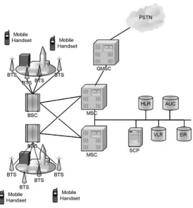
4 Mobile Networks
41
4.1 Introduction 41
4.2 Mobile network architecture and components 44
4.3 Beyond GSM, the path to UMTS 48
5 Packet Switched Technologies
53
5.1 Introduction 53
5.2 Basic Internet Protocol 56
5.3 Mobile IP 62
5.4 Transmission Control Protocol 63
5.5 User Datagram Protocol 64
5.6 Multimedia Transport 65
5.7 IP Application signalling protocols 68
6 Access Technologies
85
6.1 Introduction 85
6.2 Integrated Services Digital access 86
6.3 Digital Subscriber Line 88
6.4 Leased Lines and other fixed line services 91
7 Voice and Data Convergence
93
7.1 Introduction 93
7.2 Asynchronous Transfer Mode 94
8 Representing Information
99
8.1 Introduction 99
8.2 (X)HTML 100
8.3 XML 101
8.4 VoiceXML 105
8.5 SOAP, UDDI and WSDL 106
8.6 IPDR 110
8.7 Call Processing Language (CPL) 111
9 Directories - More Than Just Information Storage
115
9.1 Introduction 115
9.2 Domain Name System (DNS) 116
9.3 X.500 and LDAP 118
9.4 The Meta-Directory 119
9.5 Other directory technologies and ideas 119
Part II Services, Architectures and Applications
121
Introduction 121
10 Intelligent Network Services
123
10.1 Introduction 123
10.2 Example existing services and how they work 124 10.3 Softswitches and application servers 126
10.4 The future of IN 128
10.5 Voice based services 135
11 Call Centres
145
11.1 Introduction 145
11.2 Computer Telephony Integration (CTI) 146
11.3 The future for CTI 151
12 Internet Based Services
155
12.1 Introduction - the move to hosted services 155
12.2 Presence 157
12.3 Application Frameworks 159
13 Bringing it all Together - the New Network Architecture 167
13.1 Introduction 167
13.2 The next-generation network architecture 168
13.3 A service example 170
Part III Implications
173
Introduction 173
14 Expectation and Realisation
175
14.1 Too much too soon? 175
14.2 Where to now? 176
14.3 Strategies for making it happen 179
14.4 How long and How much? 182
References and Further Reading
187
Glossary
189
Index
193
Preface
The mother of invention
Telecommunications is now the fastest changing part of the IT industry, encompassing vast disciplines from distributed systems to real-time applications. I have had the pleasure of being involved in what I believe is the most exciting time in its history. It wasn’t always this way, as tele-communications started out as a novelty:‘‘An amazing invention, but who would want to use one?’’– US President Rutherford B. Hayes after making a telephone call from Washington D.C. to Philadelphia. Interestingly however, in 1879, the first telephone was installed in the White House. At first it was hardly used, because there weren’t many other phones in Washington to call [WHITEH].
From the now immortal words ‘Watson, come here!’ Alexander Graham Bell’s humble telephone1has become the most ubiquitous device on the planet. Followed swiftly in 1891 by the invention of Almon B. Strowger’s patented system of automatic switching. The Strowger switch design was so fundamental that it soon became the backbone of the World’s telecommunications network for at least the next 100 years. The story has it that Mr. Strowger (at the time an undertaker in Kansas City) was so incensed by a competing undertaker getting business and not him, because a cousin of the competitor’s worked as an operator. He decided to remove the need for operators!2From the first 99-line automatic exchange installed at La Porte, Indiana, in 1892, the telecommunications industry has never looked back. The UK followed suit and in 1912 the first experi-mental automatic exchange was installed at Epsom, by the then
Auto-1
Alexander Graham Bell patented the telephone 14 February 1876. 2
How true this story is I don’t know, but I like it anyway.
matic Telephone Manufacturing Company (later to become Plessey, then GPT and now Marconi). The rest as they say is history!
The invention of the transistor in the late 1940s also had a profound effect on telecommunications; the eventual demise of the electromechani-cal Strowger exchange, to be replaced by the current day Stored Program Controller (SPC) exchanges. Over the last 30 years the telecommunica-tions industry has been gradually improving the SPC exchanges with more features, better software engineering techniques, and increasing their capacity with more and more powerful processors. Most recently, the use ofstandardcomputing hardware and the influence of the Internet have lead to the so-called generation networks. It is these next-generation networks and the new capabilities and services that this book is about.
Motivation for the book
My aim for the book was to bring together all the technologies that at first glance seem unconnected. My view is that nothing in telecommunications is unconnected – it is the nature of the beast. One unique event can change the whole focus of the business. In recent years, that event has been the global acceptance of the Internet as an acceptable form of remote commu-nication (read telecommucommu-nication). This development has turned conven-tional telecommunications on its head. The bursting of the Internet market bubble in 2000 has also caused a ripple across the telecommunica-tions industries, with what effect, only time will tell. My own belief tells me there will be a renaissance in telecommunications – the phoenix from the ashes if you like.
I read many technical books in my role as a consultant. I need to know the answers to questions my clients ask me. My annual book budget is more than I would like to admit and certainly more than my wife would like me to spend! So I wanted to avoid the problem that I face, by putting a reference together that would cover at a reasonable level all the areas that influence and will influence telecommunications services and networks of the next generation. What I cannot achieve is a complete reference, nor would that be appropriate. I would have loved to be able to include all the technical specifications, standards and other references that I refer to in my day-to-day role. That would have resulted in another Tolstoy and I wanted the readers to enjoy the book and be happy to follow up the reference material if they wanted or needed to know more.
moved so quickly or changed so dynamically (I saw at a recent conference it likened to the US gold rush). We need to seize the opportunity of the convergence of voice networks and the Internet to deliver exciting and useful services.
Who should read this book
The smug answer is of course everyone! More realistically, the intended audience is telecommunications professionals who are working on current circuit-switched networks and are looking to see how the tech-nologies they are working with will change over the next five to ten years. Equally, engineers who are now facing the new data to carry (voice) should find this book a useful reference to show where the voice networks have come from and are going, and how this influences their role.
How to read this book
The book is split into three main parts: technology, services and implica-tions, which tries to sum up where it is leading. If you are coming from a data networking background, then you can skip the technology section pertaining to packet switching and IP in the first part of the book. If you are from a telecoms background, then you can probably skip the section on circuit-switching techniques in the first part of the book.
Everyone should find section two on services interesting. The service examples I use come from a mainly telecommunications service focus; these are the kind of services I am closest to.
Section three is where I attempt to apply some perspective to how long the services may take to develop, how money might be made from these services and who will implement them, and best of all who might use them. The topic area is replete with acronyms, so as a mechanism to improve readability I have included at the end of the book, a list of acronyms and a brief explanation of each. In addition more information about the areas covered in the book is available at the web site http://www.telecomsoap-box.org.uk. This site contains white papers and urls relating to topics covered in the book. The author can also be contacted via this web site for comments and questions about the book.
And finally I hope you enjoy reading the book as much as I have enjoyed compiling and writing it. Special thanks go to my publisher for allowing the book to be written and showing faith in me, and specifically Sally Mortimore for getting it off the ground and Birgit Gruber for keeping it going. Thanks also to Quortex Consultants for giving me a stimulating environment to work in. Don’t let anyone tell you writing a book is easy!
Part I: Technology
INTRODUCTION
As technology advances, it is a standard axiom that new ways to exploit that improvement are found. Take fibre optic cables, the first cables were used to carry hundreds of telephone conversations by utilising a single wavelength (colour) of light and modulating it with a time division signal. The creation of Dense Wave Division Multiplex (DWDM) has made that same fibre optic cable capable of carrying a significantly larger volume of information, combining many time division signals together on to the same fibre by utilising different colours of light.
Faster processors have enabled software engineers to create more useful tools and languages such as Java. Increased processing power has allowed the execution of real-time applications without having to resort to code optimisation techniques or machine language coding. The improvement in tools and programming languages, combined with the greater processing power, has lead to the proliferation of more complex services.
The massive acceptance of the Internet and better tools has meant anyone can become a web-savvy individual with their own home page. This will directly influence the capability of users of telecommunications service to manipulate and tailor their service to their own personal requirements.
influences the ability of the telecoms workforce to develop applications. As tools and service are developed, that use Internet technologies and standards, telecommunications service providers will have at their dispo-sal a larger number of individuals who can work with web style tools rather than the IN services creation environments of the 1990s.
This section explores the technologies and techniques that have lead to the next-generation network services that will emerge over the coming years. It also gives an overview of the technologies that will allow the telecommunications service providers to create new services.
In telecommunications, voice has always been the predominant appli-cation (and some might argue revenue generator, although times are changing in this respect). In the preface, it was discussed that voice has been around in telecommunications for over 100 years as a wire line service. Mobile networks in the 1980s released the tether on voice services. The Internet has and will continue to bring an application revolution to voice services. This first part of the book starts with a description of the way circuit switching functions, and explores the evolution of the circuit switch. It is the evolution of circuit switching combined with the rise in packet data networks that has enabled the so-called convergence of voice and data. The first part of the book continues with an overview of packet networks, and describes the salient information relating to how they have evolved, together with their use for transporting information in the next-generation networks. The first part of the book concludes with how infor-mation will be represented and stored in the form of XML and network directories. The combination of all of this technology will lead to the application of voice services as components of more useful services imple-mented as software executing on open platforms. This service evolution will be explored in the second part of the book.
Each chapter in this part of the book could be expanded to cover a whole book each (and has been by various authors). The brevity of the coverage is an indication of the size of the topics and is meant as an explanation of the key points. I hope the reader will follow up the refer-ences quoted for further more detailed analysis of each of the topic areas. This section is designed to highlight the technologies that will and have been influential in delivering the new world of telecommunications.
1
Circuit Switched
Technologies
1.1
THE EVOLUTION OF CIRCUIT SWITCHING
The current circuit switched network concept has remained essentially unchanged from the original electromechanical Strowger exchange (see the Preface for an explanation of how this exchange came by its name). At its most basic level the telephone network comprises transmission paths and switching nodes.
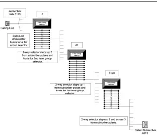
The design of a circuit switch is based on the ability to physically create a path (circuit) from one network element to another and to hold this path open for the duration of the interaction (call). The second role of circuit switching is routing, i.e. determining the path to take from the ingress point to the egress point in the network. This can be performed in multi-ple stages, each switching stage being linked by transmission paths. In the Strowger exchange routing was performed on a step-by-step basis, using the pulsed make and break signalling from the telephone dial to step electromechanical selectors.
and thus numbering plan, local, transit and international evolved. It is on this basis the worldwide numbering scheme evolved!
This example also demonstrates the physical dimensions a Strowger exchange occupied, each electromechanical selector was housed with a number of others in a metal rack. Each of these racks was placed in exchange buildings, in equipment halls. It is safe to say that nearly all Strowger exchanges have now been replaced by electronic exchanges,1 their replacements being significantly smaller, with greatly increased functionality.
BT crossbar switches (TXK) replaced a number of the Strowger exchanges in the UK. This was a major change, and out went the unise-lectors, two-way selectors and progressive control (each switching stage having its own control equipment), to be replaced by a common control and a cross point switch block. Whilst this common control function could only handle one call at a time, its operations were faster than the Strowger staged approach and so a seemingly simultaneous operation could be achieved. A similar evolution occurred in other parts of the world as switch manufacturers released newer switches.
CIRCUIT SWITCHED TECHNOLOGIES
[image:17.431.60.377.50.327.2]4
Figure 1.1 Strowger routing scheme –10,000-line, four-digit numbering
1
In the UK, electronic switching finally usurped the crossbar design in the 1960s with the TXE2 exchange, which used discrete semiconductors in the common control equipment and reed relays in the switch matrix. TXE4 and 4A came along in the 1970s. TXE4A used large-scale integrated circuits in the common control block. This was still in essence a mechan-ical exchange, with a metallic path from end to end (the TXE4s in the UK network finally disappeared in 1998). It was not until the early 1980s that the replacement of these exchanges with full digital (TXD) equipment, with high-speed semiconductor switch matrices and Stored Program Controllers (SPCs) running software (System X, DMS, AXE10, etc.),2 finally replaced their mechanical cousins.3
It was the SPC and semiconductor switch matrix, which brought about the digitisation of the telephone network. The SPC software could not only perform basic routing capability (which is what it initially performed), but also interpret more complex services. It is instructive to note that this evolution (from the end of Strowger to digital exchanges) occurred over a relatively short period (30 years).
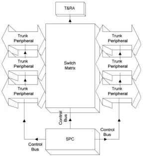
The common elements of a digital circuit switch are shown in Figure 1.2. The elements are SPC, switch matrix, trunk peripherals and Tones & Recorded Announcements (T&RA).
The SPC is the brains of the switch where all the programs that control the call state (finite state machine) reside, along with the signalling, rout-ing, maintenance, chargrout-ing, and switch matrix control programs.
The switch matrix comes in a number of forms (each switch manufac-turer choosing their favourite variation), all of them combine time (also called channel switching) and space switching. Time switching describes how timeslots from an incoming time division stream (see Chapter 2 for a description of timeslots and time division multiplexing) are disassembled from the incoming stream and reassembled on the outgoing stream. This is how ‘switching’ takes place. (I will explore switching in a little more detail in a moment, as this is quite a tricky topic!)
The role of trunk peripherals is to terminate the incoming and outgoing time division multiplexed streams. Their role is also to ensure that the streams do not get out of synchronisation, as this would be extremely detrimental (imagine if the timeslots were out of phase, the control soft-ware would be connecting the incorrect conversations together!). Timing for the whole of the switch is also derived from information gained from the trunk peripherals. Another component is the Tones and Recorded Announcments (T&RA) source. This component is responsible for
1.1 THE EVOLUTION OF CIRCUIT SWITCHING
2All trademarks acknowledged. 3
The terminology TXE stands for telephone exchange electronic and along with TXS (telephone exchange Strowger), TXK (telephone exchange crossbar) and finally TXD (telephone exchange digital) formed the generic naming of telephone exchange equipment used in the BT network.
generating call progress tones and announcements that are used to communicate to the caller the status and progress of their call. Digital switching is performed with two functions: a time switch (see above) and a space switch also known as a timeslot interchanger. In order to understand switching a basic knowledge of the transmission framing in Time Division Multiplex (TDM) is necessary. If you are not familiar with this, then I suggest you turn to Chapter 2 on the transmission infrastruc-ture.
To explain time switching, consider Figure 1.3. A bi-directional path is desired between timeslot 3 on the inbound port and timeslot 27 on the outbound port. We have already established the fact that the trunk peripherals look after synchronisation, so if a switch has all its systems synchronised, then all time division multiplexed streams of voice will be aligned. A time delay must be introduced between the two time division multiplexed streams to allow different parts of each stream to overlap (see Figure 1.3).
CIRCUIT SWITCHED TECHNOLOGIES
[image:19.431.74.361.64.378.2]6
Looking at the figure from left to right, in order for timeslot 3 of the incoming stream to line up with timeslot 27 of the outgoing stream, a delay of 24 timeslots is introduced. From right to left, since the 32-timeslot system repeats frames every 32 timeslots (on a 2.048 Mpbs stream, see Chapter 3 on transmission infrastructure), then a delay of eight timeslots from timeslot 27 is timeslot 3 in the next frame. This process is normally accomplished by the use of Random Access Memory (RAM) to store the bit pattern from each frame and a counter to index the location in the memory.
Two digitally encoded voice conversations can be connected to each other in this way, how do we achieve the connection of hundreds of thousands of connections in an any-to-any way? This is achieved by the use of a space switching stage.
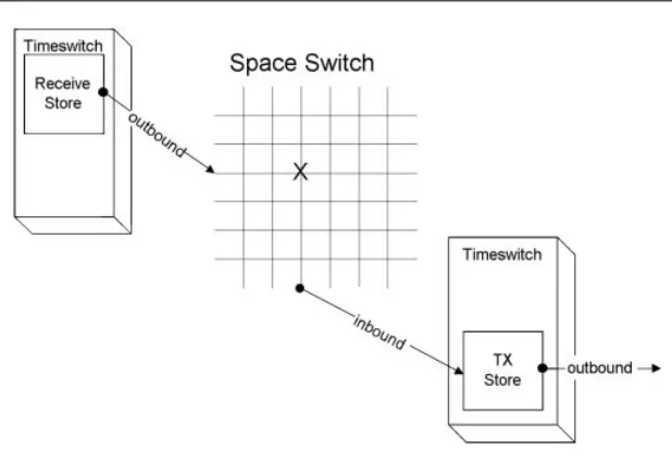
Space switching, is as the name suggests, the act of physical displace-ment of timeslots (Figure 1.4). Consider a number of time switches aligned on either side of a component that contains a number of crossover points. In order for a timeslot from one time switch to connect to another timeslot in another time switch, a cross point in the component (the space switch) would need to be active at just the right time. The space switch is a timeshared matrix allowing access to all terminations.
A speech sample arriving in a timeslot on the ingress stream is held in a receive store. When the time interval allocated to the cross point being active occurs, the speech sample is read out of the store. The sample traverses the space switch and is written into a transmission (TX) store. When the time for the speech sample to be passed on to the egress stream arrives, it is read from the transmit store.
The final configuration results in a time–space–time architecture (a space–time–space architecture is also possible). At each space switch time allocation slot, the data are read from the input time switch store and transferred across a physical path to an outbound time switch store. This outbound time switch then reads out the data in the appropriate
1.1 THE EVOLUTION OF CIRCUIT SWITCHING
Figure 1.3 Time switch operation
(delayed) outbound timeslot. As you can see this introduces delay at each switching stage.
Thankfully, not very much delay is introduced. A single frame on a 2048 kbps 32-timeslot bearer takes only 125 ms to transmit. Thus, the worst-case delay of a whole frame is only 125ms. However, if this occurs at every switching stage this delay can soon add up on international links. Switching is just one component of the connection of telephone calls across a circuit switched network. Whilst digital switching was a very important step in enabling the digitisation of the voice network that has been the enabler for the move to voice and data convergence, the one invariant throughout the history of circuit switching has been routing. Routing is the process of interpreting the digits dialled by one customer into the physical endpoint in the network of the customer they wish to reach and is performed by software running in the SPC of modern circuit switches. Routing is based on a hierarchical routing scheme embodied in the numbering plan. A numbering plan describes the structure for the organisation of the digits customers/subscribers dial to reach other subscribers.
Most people are familiar with the hierarchical routing scheme embo-died in the international numbering plan referred to as E.164. The Inter-national Telecommunications Union telecommunications (ITU-T) standard specifies a maximum of 15 digits and a geographic hierarchy for the international public telecommunications numbering plan. This numbering plan consists of an international country prefix, followed by a regional number prefix and finally a local number. This hierarchy allows
CIRCUIT SWITCHED TECHNOLOGIES
[image:21.431.61.370.53.266.2]8
for shortcuts to take place. To call a neighbour, you only need dial the local number without any prefix digits.
The telephone network is divided into local exchanges (incorporating concentration stages that concentrate access network traffic on to links to the local exchange, aka class 5 in the US), transit (or trunk or tandem aka class 4 in the US) exchanges and international exchanges, reflecting this hierarchy of routing. This basic infrastructure remained relatively unchanged all the way up to the 1980s. When the desire to increase the number of services that, the network could offer, whilst reducing the need for increasingly complex software on the SPC was achieved. This was realised by the introduction of the intelligent network architecture (see Chapter 3).
So routing is the process of interpreting the digits from this call plan into a meaningful path through the circuit switched network. Routing is a distributed stage-by-stage process in telephony, with switches at different levels in the hierarchy taking responsibility for different stages in the routing.
By way of an example, consider the number 44-1189-428025. This number has been artificially partitioned into international country code (44), followed by national prefix (1189) and finally the local digits (428025). If a subscriber chose to dial from another country (other than the UK, 44 being the UK country code) then the whole number would be required in order for the telephone network to route the call. If a caller based in Reading (UK) wanted to reach the customer whose number was 428025, then they need only dial this shorter digit string. This is because in the latter case the local exchange that both customers/subscribers are connected to contains sufficient information in the program in the SPC to determine the equipment (and thus subscriber’s line) that the number relates to.
If the caller was outside the area they would call 01189 428025 (in the UK). The local exchange that the caller is connected to would have to pass the number up to a transit exchange. The transit exchange could then determine if it needed to pass the call on to another transit exchange, or if it had the local exchange that the number related to directly connected to it. The transit would then pass on the digits to the next exchange in the hierarchy. In order for exchanges to communicate in this way a mechan-ism for passing the information between exchanges and signalling responses back about the results is needed. This is the topic of the next section.
One final note, the hierarchical approach to routing has been driven by cost as much as numbering plans. The cost of trunking large volumes of copper wire and hence subscriber lines over long distances is significant. The twisted copper pair in most homes is aggregated by local exchange switching centres and carried over multiplexed co-axial and fibre links to the tandem exchanges. We will discover (in Chapter 5) that packet-based
voice networks allow us to flatten this infrastructure in a cost-effective way.
1.2
SIGNALLING – COMMUNICATING BETWEEN
SWITCHING POINTS
Signalling is the term used to describe the messages that are interchanged between the switching points in order to facilitate the communication of what is known as call progress information. What this statement means is that a mechanism must be in place that allows the communication between telephone exchanges (which are computers in the case of modern digital exchanges) of the dialled digits that a customer dials to reach another customer and a means for errors to be communicated back to the instigating switch (or even customer).
In keeping with the evolution of switching components, the signalling and transmission components have also followed an evolutionary path both at the network edge and in the core of the network.
The edge of the network has slowly undergone the replacement of the loop-signalling interface to a dual tone signalling method (DTMF also known as MF4). Loop signalling is, as the name suggests, a means of signalling the digits dialled by making and breaking a loop circuit between the telephone handset and the local exchange, the loop being formed using the copper twisted pair cable connecting the telephone handset with the telephone exchange. Dual tone multifrequency (DTMF) or multifrequency signalling number 4, as it is also known, is a mechanism that utilises a collection of audible tones arranged in pairs associated with each button on the key pad of a modern telephone handset.
The introduction of digital access signalling at the edge of the network has occurred in the form of a number of different protocols namely:
† Digital Access Signalling System (DASS 1 and 2), a UK centric proto-col designed by BT and now largely superseded by DSS1.
† Digital Private Network Signalling System (DPNSS).
† Q.931/I.451 (more accurately known as DSS1 the other two are the call control protocol standards), used for integrated services digital network (ISDN) call set-up signalling for basic and primary rate connections between customer premise equipment and local exchanges. This is also largely being replaced in Europe by Euro ISDN a standard developed by Europe Telecommunications Stan-dards Institute (ETSI).
† Q.SIG, an amalgamation of Q.931 and DPNSS capabilities for signal-ling for basic and primary rate connections between customer premise equipment and local exchanges and the construction of private networks.
CIRCUIT SWITCHED TECHNOLOGIES
† The US has Telcordia specified ISDN 1 and 2 protocols and Japan has INS-Net defined by NTT.
† V5, a protocol designed for the connection of concentrator switches to local exchanges. It has two versions (V5.1 and V5.2), the second version having more features.
These protocols have allowed the introduction of more sophisticated devices at the edge of the network and through this the evolution of more complex services including circuit switched data services (see Chapter 6). We will not cover these protocols in any more detail, suffice to say they all provide a similar service. That of connecting digital/electronic equipment such as Private Branch Exchanges (PBXs) and Automatic Call Distributors (ACDs) to the public switched telephone network and other private networks. The key point about the move from analogue signalling at the edge of the network to digital signalling is the increase in services and facilities that can be supported, and for example the ability for end devices to communicate with each other, using the public switched tele-phone network as a packet data network for carrying those messages.
One facility that makes good use of this is route optimisation. When two private exchanges (PBXs) are connected together through a number of other exchanges (as transiting exchanges). One of the parties in the call wants to redirect their end of the call to a third person and hang up (transfer the call). The route the new call takes can be optimised by drop-ping the path of the call back through a number of the intermediate exchanges until it passes through the minimum number of exchange links. This facility is provided by signalling messages that pass between the edge PBXs and intermediate nodes to establish the new route.
The core network signalling, in concert with the access network signal-ling, has evolved from analogue-based signalling in the form of:
† Loop disconnect (see above) this is a form of direct current signalling that is only effective over circuits up to about 2 km.
† E&M, stands for ear and mouth signalling, this is a two-way signal-ling mechanism, ear being the receive signalsignal-ling and mouth the trans-mit signalling.
† DC2 and DC3, use current pulses to signal digits and trunk seizures between exchanges.
† AC8, AC9, AC11 and AC12, these are all what are referred to as out-of-band and in-band signalling systems. They use frequencies of sound outside those normally permitted for voice (artificially filtered) and sounds inside the voice range.
† MF2, like its cousin MF4 (see above), was used for speeding up the transmission of decadic digits between trunk exchanges by encoding the digits as a set of in-band tones.
† R1 and R2. Signalling systems R1 (North America) and R2 (Europe) are used for inter-register signalling. Inter-register signalling
(between trunk exchanges) uses MF in-band pulse signalling at frequencies of 700–1700 Hz, in 200 Hz steps, for the transmission of address information. Line signalling is performed in TDM systems as a set of bits (normally in channel 16 of a 32-channel system and using bit robbing in US 24-channel systems – see Section 2.2).
To a digital packet-based signalling system called signalling system number 7 (SS#7). I can hear what you are thinking, ‘‘What happened to the other SS#x?’’ SS#4, 5, 6 are international analogue signalling systems specified by the then CCITT (ITU) in the early 1960s. I will not cover any of the analogue signalling systems in this text because, whilst their impor-tance is recognised, they are largely being/have been replaced by packet-based digital signalling in the form of SS#7 in the Public Switched Tele-phone Network (PSTN).4 The move over to packet-based systems is because of a number of reasons. In the previous (analogue) signalling systems mentioned:
† a direct relationship exists between the telephony traffic route and the signalling (in packet-based signalling the messages can follow inde-pendent paths to the telephony traffic);
† only telephony data could be signalled (in packet-based signalling, network management messages, statistics information and fault reports are all carried over the signalling system);
† the number of messages are limited;
† the signalling transfer of messages is slow; and
† equipment is inefficiently used because it was generally dedicated to a specific route.
This brings us neatly on to the now universally accepted packet-based signalling system, SS#7.
Overview of Signalling System Number 7 (SS#7)
This section covers the signalling protocols set out in the ITU-T5 standar-disation sector specifications known as the Q.700 through to Q.775 series of recommendations. The term recommendation is an interesting one in that it implies they are not compulsory, however, without almost univer-sal adoption by telecoms equipment manufacturers and network opera-tors nothing in the telephone network would work, and would not have moved beyond operator-connected calls.
CIRCUIT SWITCHED TECHNOLOGIES
12
4
I’m certain to get remarks over this point, as I’m sure a significant amount of interna-tional analogue signalling still exists! The important point is the move to digital signalling and what that enables.
5
The ITU-T recommendations have peer specifications from the Amer-ican National Standards Institute (ANSI) and Bellcore (now Telcordia Technologies) for the North American variants of SS#7, also regional variants exist, for example Japan, and in the UK, the Telephony User Part (TUP) protocol is known as IUP and formally as BTUP. A good reference for a more detailed study of these specifications and SS#7 in general can be found in [RUSS]. By completing this section, you will be rewarded with a good foundation to take you through to how and why intelligent networks work.
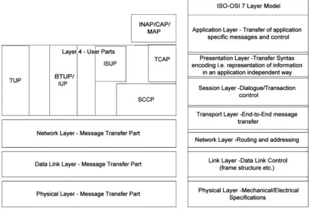
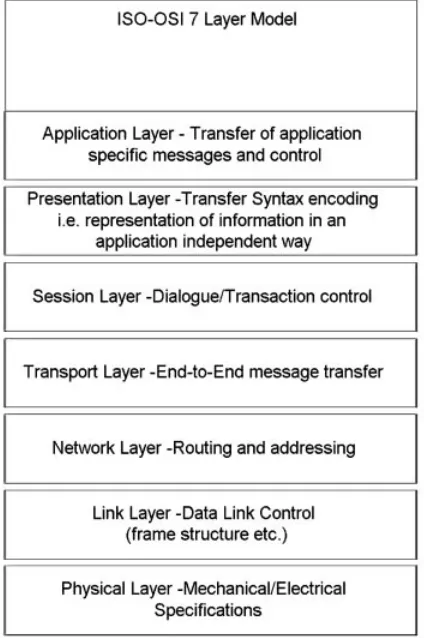
In order to discuss SS#7, an understanding of the International Stan-dards Organisations – Open Systems Interconnection (ISO-OSI) seven-layer model is not necessary (but helpful). The specifications for SS#7 were put together before the ISO model and thus the protocol stack only has four levels (not seven like the OSI), message transfer part (levels or layers 1–3) and user parts layer 4 (the Q.700 document describes this structure). These roughly equate to the OSI layers 1 through 5 (physical, data link, network, transport, session). The presentation and application layers of the ISO stack strictly speaking are not present in the SS#7 stack, however, some of the presentation layer functions are included in the SS#7 transaction capabilities layer. The ISO-OSI transport layer is not applic-able to Message Transfer Part (MTP) layer 3, as MTP does not make use of connection oriented services. However, some applications make use of a connection oriented service present in Signalling Connect Control Part (SCCP), hence why in Figure 1.5 the ISO transport layer overlaps the
[image:26.431.57.365.370.580.2]1.2 SIGNALLING – COMMUNICATING BETWEEN SWITCHING POINTS
Figure 1.5 SS#7 four-layer protocol stack
bottom portion of the SS#7 SCCP layer. Figure 1.5 shows the SS#7 protocol stack in comparison to the ISO-OSI seven-layer model, this is only to give a perspective on how the SS#7 protocols function and doesn’t represent a direct relationship between the two.
Figure 1.5 shows INAP, CAP and MAP protocols in layer 7 (application layer). These are included in the figure for completeness and are discussed in Chapters 3 and 4, respectively. INAP stands for intelligent network application protocol and provides the functionality to support enhanced services in fixed networks. CAP stands for Customised Appli-cations for Mobile Networks Enhanced Logic (CAMEL) Application Part and MAP for Mobile Application Part, both protocols for mobile networks that provide enhanced application functionality specifically with mobility in mind.
Message Transfer Part
The Message Transfer Part (MTP) covers layers 1 through 3, we shall take these in turn from layer 1 through to layer 3.
Layer 1 covers the physical presentation of the signalling, this specifies either a V.35 interface or a single TDM slot (DS0A – bit stolen signalling channel see Chapter 2 on framing for an explanation of bit robbing, or DS0C – clear channel 64 kbps). In most networks (fixed and mobile), the signalling is carried over a TDM slot, as these are readily available from the transmission infrastructure (see Chapter 2).
It is common in the telephone network for the signalling channels to be carried alongside the voice channels as a clear channel 64 kbps bearer in timeslot 16 (in Europe) of a 32-timeslot system. The individual timeslots are commonly referred to as bearers and/or channels. The signalling is multiplexed into timeslot 16 from the signalling software on each of the switch nodes by the switch matrix function. A complete packet-based signalling infrastructure is constructed in this way, embedded in the TDM transmission bearers between the switches. This is an important point and highlights the fact that MTP, and in fact SS#7, is a packet-based system. In theory, there could be a completely separate packet switched network, from the circuit switch voice connections. The use of the multiplexed voice channel systems to carry the signalling packets is a convenience, not a necessity.
The construction of the signalling links and the association of the links to the signalling entity it provides a service to, are generally constructed using configuration data (commonly known as datafill) on the switch. The link types are separated into modes. These modes of signalling come in three forms: associated, non-associated and quasi-associated.
Associated signalling is when the signalling in the timeslot has a direct relationship with the speech channels on the link it shares. This mode of signalling is commonly used to signal messages about an analogue
term-CIRCUIT SWITCHED TECHNOLOGIES
inal on a multiplexor. In the case of a 32-timeslot system, timeslot 16, that contains 8 bits, is subdivided into two 4-bit parts. The lower 4 bits are associated with information about the voice connections in the timeslots below 16 and the upper 4 bits contain signalling information for the upper 15 speech channels.
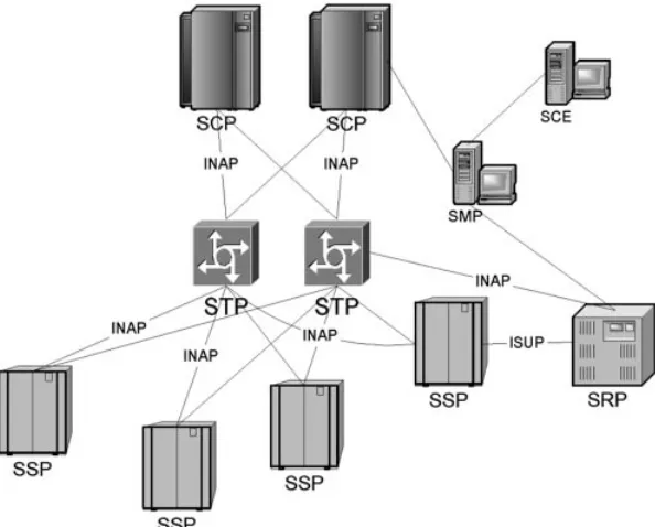
Non-associated signalling uses a separate path to carry the signalling information from the voice bearers that are used to carry the voice chan-nels (Figure 1.6). In this instance, a separate packet switched network connection is essentially constructed. It is at this point we will introduce the term Signalling Transfer Point (STP). A STP is the SS#7 equivalent of a router. In most cases, the STP is an adjunct function embedded in the circuit switch, composed of hardware and software components (in the SPC). The circuit switch is used to connect the timeslot 16s through to a number of ports on the switch that have special trunk peripherals that connect the signalling channels to the control bus, and thus the signalling messages to the software on the SPC (see Figure 1.2). In non-associated signalling, messages can actually transit through a number (one or more) of intermediate routing points before reaching their destination.
In quasi-associated signalling, the two signalling endpoints are connected to the same STP and the signalling path is separate to the voice path.
In order to provide capacity and redundancy for signalling, a number of signalling links (up to 16) can be grouped together into what is called a
linkset. If more than one link is provisioned into a linkset, then the messages are load shared across the links. These linksets are then grouped into routes, if all the linksets the group can be used to reach a particular signalling destination. Routesets are then defined as collections of routes. This grouping is to allow the STPs to find alternative routes to a destina-tion for example during a failure of equipment.
Clearly, a connection to only one STP would be unfavourable from a resilience perspective and with reliability as one of the key design criteria it would be unwise to only be able to connect the signalling point in a
1.2 SIGNALLING – COMMUNICATING BETWEEN SWITCHING POINTS
Figure 1.6 Signalling modes
switch to a single STP. The standards allow for this and two STPs can be combined into a pair, with associated paired signalling linksets from a switch node.
If you read the associated standards, you may be confused by A-links (access links), B-links (bridge links), etc. all the way up to E- and F-links (extended and fully associated links). Do not worry about these, they are all the same, it is just which equipment endpoints they are connected to that makes them different, they function in the same way as an overlay of bearers for the support of the packet switched signalling network.
MTP layer 2, the data link layer is responsible for reliable sequenced delivery of all SS#7 messages, and it achieves this on a node-to-node basis. The key feature of MTP is reliability. The specification of MTP goes to extreme lengths to provide a reliable transport mechanism for user part protocols. MTP layer 2 provides both sequence numbers for the messages it sends and a cyclical redundancy checksum for the packet. Any messages found to be in error or lost are retransmitted by MTP layer 2.
Layer 3 of MTP (the network layer), is responsible for the routing of messages, message discrimination and message distribution. Message discrimination determines if the message is for a local layer 4 protocol or if it is for another node. If it is a local message, then it passes the message to the distribution function for delivery to the appropriate layer 4 user part (protocol, for example ISDN user part (ISUP)). If the message is destined for another node, it passes the message to the routing function. Layer 3 also performs the vital role of supporting network management. Network management in MTP constantly monitors the links for errors and congestion. MTP has special messages called ling units and in particular a message signalling unit. The message signal-ling unit message is used to automatically reroute messages around failed links by instigating what is called a changeover. Changeover is in essence a way for the signalling transfer points to inform each other of a failed signalling and start sending signalling information down the partner link of a signalling linkset.
Addressing in layer 3 is determined by what are called point codes. Every signalling function in every switch in all the inter-connected SS#7 networks in the world has a point code. In this way, MTP layer 3 is comparable to the Internet Protocol (IP) and a point code comparable to an IP address.
User Part Layer
Layer 4 is where the call control signalling and some application signal-ling are located. For example ISUP is a call control protocol which speci-fies how connections are set up and torn down. ISUP was designed to work in concert with the Q.931 digital access signalling system and allows for the connection of both telephony and switch data services amongst
CIRCUIT SWITCHED TECHNOLOGIES
other services such as call forward and calling line identification (called Automatic Number Identification (ANI) in the US).
TCAP (Transaction Capabilities Application Part) is an application protocol for accessing databases. You see TCAP being used in intelligent networks to carry INAP messages (see Chapter 3 for more on intelligent networks). TCAP is a complex protocol and implements a lot of the services present in the ISO session layer, and some of the ISO application layer functions.
TCAP makes use of the services of the protocol known as SCCP (Signal-ling Connection Control Part). This protocol provides another layer of addressing beyond point codes,subsystem number. This subsystem number is used to reference a particular instance of a service or a specific database. SCCP also provides services to the TCAP layer more akin to services offered by the ISO transport layer, namely: a connectionless service (sequenced and un-sequenced), a connection oriented service and a flow control connection oriented service. SCCP provides the end-to-end service for messages that MTP does not, as such SCCP supports message transfer and routing between non-telephony applications, i.e. database lookups.
There is a special routing stage that can take place in the SCCP layer that is very powerful. This routing capability is calledGlobal Title Transla-tion(GTT). What GTT does is to associate a service request code (an 800 number for example) with a point code and subsystem number. This routing capability takes place in the STPs. Why is this important? Well GTT means that fault tolerance and load sharing across service points (or databases) can take place without the invoking switch being aware of it happening, you will see the importance of this in Chapter 3, on intelligent networks.
We are going to take a brief interlude from switching and signalling to cover transmission systems, and then we will pick up advance telephony services in the form of intelligent networks in Chapter 3 and explore the use of SS#7 for more advanced services.
2
The Transmission
Infrastructure
2.1
INTRODUCTION
We pass by transmission on the way to the Intelligent Network (IN) because it is important to understand how all the switching and signalling nodes (not to mention voice links) are connected together. Like the last chapter, we will pass briefly through analogue transmission first as a means of exposing the desires for digital transmission. Then move on to digitisation of speech and look at how large volumes of calls are econom-ically carried across the world.
Analogue voice signals can suffer from a number of interference problems ranging from degradation due to distance through to external signalling inducing noise into transmission. One of the big culprits for ‘noise’ on the line is cross talk. Cross talk occurs when a number of transmission systems are carried through the cabling trunk in close proxi-mity. External noise in the form of interference from electricity mains cabling and other electronic equipment conspire to reduce the speech to an unintelligible hiss. It is this reason as well as economies of scale in amalgamating voice connections together into large transmission systems that has brought about the desire to digitise the analogue signals produced by the human voice. Digital signals are less prone to interfer-ence as interferinterfer-ence only indirectly affects the signal. The original analo-gue signal must be decoded from the binary representation, as long as the accuracy of the binary representation of the signal is maintained the original signal can be regenerated immune from noise.
2.2
VOICE DIGITISATION
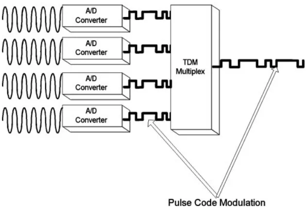
Speech using the handset concept created by Alexander Graham Bell is an analogue signal. It is a continuous signal, varying in amplitude and frequency in sympathy with the compression waves created from the human voice box in the process of producing speech. In order to represent this accurately as a digital signal, it must undergo three processes: filter-ing, samplfilter-ing, quantising and encoding (these latter two being a single step).
Filtering is the process of eliminating frequencies beyond a certain range. The audible range is from around 20 Hz to 20 kHz. The majority of information from a human voice is actually present between 300 and 4000 Hz (the human ear’s maximum range of sensitivity is from around 1 kHz up to around 5 kHz). This frequency range is used in most telephone systems around the world to convey the voice of the person speaking. The reason for this filtering probably goes back to analogue transmission of multiple voice signalling using a technique known as Frequency Division Multiplexing (FDM). Basically FDM uses collection of frequencies and modulates them with the original voice signal. The modulation changes the base frequency up and down in sympathy with the changes in the voice signal. Clearly the broader the spectrum of frequencies present in the voice signal the more the base frequency would vary, this would have the effect of limiting the number of separate voice ‘channels’ that could be carried on an FDM trunk. By artificially constraining the voice to a limited range (300–3400 Hz in Europe and 200–3200 Hz in the US) of frequencies the capacity of the FDM trunk could be increased.
Sampling is the process of taking discrete moments in time and measur-ing the value of the amplitude (loudness) of the audio signal. The sampling rate used for telephony is 8000 times per second. Why this rate, a mathematician named Nyquist proved a sampling theorem that states a signal’s amplitude must be sampled at a minimum of twice the highest frequency of the signal. Since the maximum frequency allowed by the filter is 4000 Hz, then a minimum sampling rate of 8000 times per second is required for a 4000 Hz signal.
Finally, to convert the sampled signal called a Pulse Amplitude Modu-lated (PAM) (Figure 2.1) signal into a set of binary pulses, the PAM sample must be given a discrete value. This value, in the scheme used for the circuit switched telephone network is an 8-bit binary value in the range of 1127 to 2128, thus including zero a range of 256 distinct amplitude levels.
Ideally, more levels (in fact an infinite number) are necessary to truly represent the signal. Eight bits are seen as a sufficient compromise for voice signals in telephony. For example in compact disc (CD) recordings the signal is sampled 44,100 times per second, and a range of values of 65,536 are used to represent the sound. To think about what is happening
here, as the sample rate is increased and the number of values (precision) used to represent the analogue waveform increase, the digital sampling is tending closer to the actual analogue signal it is trying to represent. At infinity the digital pulses become a continuous waveform, essentially the original analogue waveform!
This results in what is called a Pulse Code Modulated (PCM) signal. The encoding (actually called companding, because this signal is first compressed from 12 bits to 8 bits then expanded in the decoder to 13 bits) part is actually performed using an approximate logarithmic scale (the step value is doubled for every doubling of the input level); this is to avoid unacceptable errors (due to approximation) for small amplitude signals and incidentally is how the human ear resolves sounds. The scale used is either an A-law (European) or a m-law (North America) companding. If you would like more detail on this topic, then I refer you to [HALS, HERS], both of which cover this topic well.
A-law and m-law are actually an International Telecommunications Union telecommunications (ITU-T) standard known as G.711 encoding. Other encoding techniques exist for lower bit rate transmission such as:
† ITU-T G.726 – adaptive differential PCM (ADPCM), with bit rates as low as 16 kbps. ADPCM reduces the bit rate by dynamically changing the coding scale and only encoding differences from one sample to the next.
† ITU-T G.728, 16 kbps low-delay code excited linear prediction (LD-CELP). This algorithm uses a look-up table to extract values for the
2.2 VOICE DIGITISATION
Figure 2.1 PAM sampling of an analogue signal
voice sample and provide compression of 64 kbps PCM signals down to as low as 16 kbps.
† G.729 8 kbps conjugate-structure algebraic-code-excited linear prediction (CS-ACELP). ITU-T G.729 has been added to in the form of annexes to the original specification and vendors have implemen-ted these, resulting in products such G.729a, referring to an annex A implementation.
These encoding schemes won’t be examined further in the text here, and readers who want to know more are referred to the relevant stan-dards or [HERS]. Just one final note on encoding that is important when it comes to the next generation of packet-based telephony. As more compression is introduced in the companding scheme, the resulting bit stream encodes more information and as such becomes more sensitive to bit errors and frame/packet loss. As the telecoms world moves to imple-ment Voice over Internet Protocol (VoIP) solutions and looks to gain economies through compressing the speech for transmission, this can only be achieved at the cost of quality.
The bit stream resulting from the companding process can be combined with many others to form a single serial bit stream (Figure 2.2). The combination of each discrete stream is created by time slicing each one in turn on to the serial transmission line. Since we are producing 8 bits of data, 8000 times per second, the resulting bit rate is 64 kbps. Each 8-bit sample occurring ever 125 ms. This means in order to create a system containing 32 timeslots, each individual stream must be sampled every
[image:35.431.59.376.371.585.2]THE TRANSMISSION INFRASTRUCTURE 22
125 ms, resulting in a gross bit rate of 8000£32£ 8¼2.048 Mbps. This stream is known as a primary rate stream or an ITU-T E1 system.
The final stage in the process of producing a time division multiplex stream that can be transported over a reasonable distance on copper co-axial cables is line encoding. Line encoding serves the following purposes: to create few low frequency components, create no zero frequency compo-nents, encode timing information and finally to provide a means of moni-toring for errors caused by loss or noise on the transmission line.
The encoding technique explored here is called high density bipolar 3 (HDB3), which is an ITU-T specification used in E1 2.048 Mbps transmis-sion lines (see ITU-T G.703 for more information). This encoding scheme ensures that there are no long streams of zeros or ones present on the transmission line. It achieves this by the following rules: binary ones are transmitted alternately as either a positive voltage or a negative voltage (a mark), a binary zero is transmitted as a zero voltage. This is essentially what is called Alternate Mark Inversion (AMI). A number of other encod-ing schemes exist to meet the same purpose (Non-Return to Zero (NRZ), AMI, Manchester coding, Zero Code Suppression (ZCS), Bipolar with 8 Zero Substitution (B8ZS) and Zero Byte Timeslot Interchange (ZBTSI), to name a few). B8ZS is widely used in North American transmission systems, whilst HDB3 is used outside North America.
For HDB3 encoding, in any sequence of four consecutive zeros, the final zero is substituted on the transmission line with a mark of the same polarity (1ve or2ve) as the previous mark (this is called a bipolar viola-tion). If a long stream of zeros were present then clearly every fourth zero would be replaced by a mark on the transmission line, however, succes-sive violation marks of this nature are of opposite polarity. Why, since applying the rule above is each bipolar violation of the same polarity as the previous mark? This is because where successive violations would be of the same polarity, abalancemark is inserted by setting the first digit of a sequence of four zeros to be a mark of the opposite polarity of the previous mark. Lost, maybe Figure 2.3 will help.
2.2 VOICE DIGITISATION
Figure 2.3 HDB3 coding
These violation marks and balance marks also serve the purpose of embedding a timing signature into the transmission. This is achieved through the frequent transitions of the signal.
Timing (synchronisation) was mentioned earlier in the section on switching where it was pointed out that the importance of timing was to ensure conversations between two people could be accurately connected together. In the discussion on HDB3 we saw that timing is coded into the line signal by ensuring adequate pulse density. The encod-ing also serves as an error detection mechanism; any bit errors created by interference can be detected, and in some instances automatically rectified in the receiver. The final piece of the puzzle for ensuring the channels of the conversation you want to connect are the correct ones is in the use of framing.
Each collection of 32 timeslots of the ITU-T E1 Time Division Multiplex (TDM) (24 in a North American T1) serial pulse train is called aframe. This frame is combined into multi-frames. In fact 16 frames in all make up a multi-frame (Figure 2.4).
The 32 timeslots are divided into timing slots, voice bearers and signal-ling bearers. Timing is embedded in the framing structure by placing special sequences of bits (bit patterns) into timeslot 0 in consecutive odd and even numbered frames and one special multi-frame alignment pattern in timeslot 16 of frame 0. All the other timeslots: 1 through 15, 17 through 31 carry the speech channels and timeslot 16 in all the other frames other than zero carries signalling information. Thus synchronisa-tion of the speech channels is achieved.
In the North American Digital Stream 1 system, a different scheme is
THE TRANSMISSION INFRASTRUCTURE 24
used to carry 24 voice channels in a frame. Signalling is carried in this scheme by borrowing a bit out of each of timeslots 6 and 12, respectively (as opposed to a dedicated timeslot), this scheme is commonly known as bit robbing.
To finally finish off the topic of timing in a TDM network, the type of timing is expressed in three words: synchronous, asynchronous, plesio-chronous. Clearly, we can discount asynchronous, since the whole topic so far has concentrated on synchronising voice channels. Synchronous can be discarded since this implies all the clocks in all the exchanges are in complete synchronism, which is not the case, because a single clock source connected directly to all exchanges would have to be present. Plesiochronous on the other hand means ‘nearly’ synchronous and that is just what a TDM voice network is. In fact a hierarchy of timing is present in a TDM voice network. With the master source generally being a caesium clock, this clock source is rippled down through the international exchanges to the transit/trunk exchanges and finally to the local exchanges, using the timing mechanisms embedded in the bit streams carrying voice and signalling discussed above (see ITU-T G.810, G.811 and G.812, if you are interested). All this is in place to guarantee that once a connection is set up between one endpoint and another, it remains connected with little or no change in delay (variance in delay is commonly referred to as jitter) and no loss of clarity, through the loss of voice samples. We will see later when we discuss packet-based voice commu-nications just what a legacy this is.
Therefore, that is how a collection of 30 speech channels is placed on a serial transmission line. What we do not want to do is put lots of single E1 or T1 links in the ground. This clearly would not be economical. There-fore, we need a means by which we can combine the E1s into a collection of E1s for economic transmission. That is where PDH, SDH, ATM, DTM and DWDM come in (each of these acronyms will be explained in turn in the following sections).
2.3
PLESIOCHRONOUS DIGITAL HIERARCHY
In the previous chapter, we covered how individual digitally encoded voice samples are combined into 32 timeslots 30 channels of voice E1, or 24 channels of voice T1. To economically carry lots of these voice bearers across the world, and maintain the timing of the switched network Plesiochronous Digital Hierarchy (PDH) was created. Across the globe three systems of PDH exist, one in North America (where it was first invented by Bell Labs, now part of Lucent), one in Europe and one in Japan. The three variants all share one thing in common, they all specify five levels of multiplexing.
Simply put the PDH network is an aggregation of E1/T1 bearers in
higher bit rate systems by multiplexing the lower order E1s/T1s together. The ITU-T specifies the following higher order bearers: E2 (8.448 Mbps), E3 (34.368 Mbps), E4 (139.264 Mbps) and E5 (565.148 Mbps).
The North American system refers to each level as digital streams (DS). DS0 is the bottom and represents a single 64 kbps channel, DS1 is the 24-channel system (also referred to elsewhere in the book as T1. T1 is the colloquial term used that was actually a reference to the four-wire trans-mission system). DS1c is two DS1s, and DS2 two DS1cs, DS3 (also collo-quially referred to as T3, although strictly speaking there is no such thing as a T3) is seven DS2s.
The smart reader will spot the bit rates in the European PDH are not exact multiples of 2.048 Mbps, why is that? In the same way the E1 combines framing information with the voice and signalling, we need to do the same with the higher order bearers. These additional signals are because each of the TDM streams all have a slightly different timing source. This means we need to compensate for this. This is achieved by clocking at a slightly higher bit rate than the sum of the lower order bearers (called tributaries and sometimes colloquially referred to astribs
by engineers). Any unused bits are filled with what are called justification bits and alarm signals to indicate failures such as loss of synchronisation. This results in a collection of nearly synchronous bit streams, hence plesiochronous.
This type of network infrastructure still exists today, but is slowly being replaced by our next technology Synchronous Digital Hierarchy (SDH). More on that in a moment, the obvious question is why replace it? The less than obvious answer (maybe) is cost. Consider the collections of E1s all aggregated on to higher and higher rate bit streams, all slightly displaced within the higher order streams by varying amounts of justification bits. This makes it impossible to determine (without de-multiplexing) where each individual E1 starts and ends.
Why is having a hierarchy of multiplexers a problem? Remember when we discussed switching, each switching stage has trunk peripherals, these all terminate E1s or T1s. The switching stage then interchanges timeslots on these bearers to connect speech channels together. The Public Switched Telephone Network (PSTN) is a web of switch nodes connected together by transmission infrastructure. In the case of PDH this is a collection of E5 bearers between major cities (trunk exchanges). Each time a telephone connection is required between cities, the multiplexed collection of E1s will need to be de-multiplexed to get access to the voice channel. In each exchange building there is a large investment in multiplexing equipment. This also extends all the way to the edge of the network in what are called Points of Presence (POP), which the network operator uses to bring custo-mer connections into the network. Figure 2.5 shows the situation.
To alleviate the problem of large multiplexer hierarchies and to increase the rates of multiplexing, SDH was created, to capitalise on the significant
installed base of copper twisted pair, co-axial cables and fibre optic cables left as the 30-year heritage of PDH (first-generation transport system).
That was rather a whirlwind tour of PDH, but explains the basics of the infrastructure that grew up with digital switching over the last 30 years. If you would like to know more, then I recommend you consult the ITU-T G.702, G.703, G.704 and G.706 specifications.
2.4
SYNCHRONOUS DIGITAL HIERARCHY AND
SYNCHRONOUS OPTICAL NETWORKS
Synchronous Optical NETworks (SONET) was initially specified by American National Standards Institute (ANSI) and Bellcore (Telcordia) in the early 1980s and taken up by the ITU-T to form the SDH standards. It wasn’t until the early 1990s that equipment started to appear. This description belies a fraught process; at one point the SONET proposed framing structure of 13 rows by 180-byte columns; whilst the SDH speci-fication advocated a 9 rows by 270-byte column. These differences were brought about by the differences in the basic blocks of transmission that needed to be carried, namely T1 (1.544 Mbps) and E1 (2.048 Mbps). Finally, both standards bodies saw sense and settled on a 9-row frame, wherein SONET became a subset of SDH.
What is the main differentiator between SONET/SDH and PDH? The two words in its name give it away – synchronous and optical. Unlike PDH, synchronisation is maintained throughout the network, and large capacity transmission paths are created over fibre optic cables. Some might argue that SDH is no more synchronous than PDH, whilst this could be argued based on the fact that the bearers/tributaries carried in SDH frames are not in synchrony (stuffing bits are used to cater for fluc-tuations in the timing of the tributaries – this is explained a little later when the SDH frame structure is explained) the rest of the network is.
The subtlety of the difference between SDH and SONET is shown in Table 2.1. SONET describes Synchronous Transport Signals (STS) and
2.4 SYNCHRONOUS DIGITAL HIERARCHY AND SYNCHRONOUS
Figure 2.5 PDH infrastructure
Optical Carrier (OC) signals as the basic building blocks. An STS is noth-ing more than a framnoth-ing structure that defines how data can be multi-plexed into the SONET hierarchy. SDH defines Synchronous Transport Modules (STM) – again a framing structure. The lowest rate SDH frame starts at 155 Mbps, whereas SONET starts at 51 Mbps. This difference in base rate also means that the base frame and multiplexing structure are also different to accommodate the difference in bit rates.
This results in an STS-1 having a frame size of 90 bytes by 9 rows, and an STM-1 a frame size of 270 bytes by 9 rows. In line with the previous section on PDH, because the speech is sampled at 8000 times per second, each rectangular 9 rows byx-byte columns are transmitted every 125ms. Resulting in the gross bit rate of 9£270 £8£ 8000¼155.52 Mbps and 9 £ 90 £ 8 £ 8000 ¼ 51.84 Mbps, for STM-1 and STS-1, respectively. SONET and SDH achieve synchronisation by the use of a single master clock. In order to accommodate plesiochronous tributaries, pointers are used in the frame header. These pointers are values in the frame that indicate the offset of the particular multiplexed unit (E1, T1, E3, etc.) in what is referred to as thepayload. Each frame consists of a header area and a payload area.
The header contains in SDH an area referred to as thesection overhead. This section overhead is subdivided into: regeneration section overhead,
administration unit pointers, where the pointers to the payloads reside, and finally themultiplex section overhead.
In SONET the header is referred to as a transport overhead. This is subdivided intosection overhead and line overhead. This is where I end my discussion on SONET and concentrate on SDH (Figure 2.6 shows the frame structures). For a more detailed coverage of SONET see [BLACK1]. The payload area of the frame in SDH contains the multiplexed streams and apath overhead. The path overhead is essentially an area where moni-toring information can be stored in the frame, for example to monitor the
THE TRANSMISSION INFRASTRUCTURE 28
Table 2.1 SONET and SDH transmission rates and names
SONET SDH Bit rate (Mbps)
STS-1/OC-1 51.84
STS-3/OC-3 STM-1 155.52
STS-9/OC-9 466.56
STS-12/OC-12 STM-4 622.08
STS-18/OC-18 933.12
STS-24/OC-24 1244.16
STS-36/OC-36 1866.24
STS-48/OC-48 STM-16 2488.32
STS-96/OC-96 4876.64