International Journal of Innovative Technology and Exploring Engineering (IJITEE) ISSN: 2278-3075, Volume-9 Issue-2, December 2019
Heat Transfer Properties in Microchannel by
Varying Aspect Ratio: Experimental and
Simulation
Ajneesh Kumar, Gurjit Boparai
Abstract: In this paper study the heat transfer rate in a branched and rectangular micro channel. Using the aspect ratio of height and width were 1:1 for straight channel and 0.75/1 for branched channel. This experiment was done for same convective area 60 mm2. This experiment was study how to affect the aspect ratio to temperature drop. The change of effect the aspect ratio we are found by simulation by using the other branch channel aspect ratio (1) or straight micro channel aspect ratio (1.37) and the same area 47mm2. These different aspect ratio straight and branched channels compare to each other. Then studied after this experimental data as a function of aspect ratio increase the 20% of friction constant evidence at low aspect ratio. Then the wall temperature is carried 92⁰c and heating the heat sink at 90 watts. Using the convective heat transfer in the micro-channel. Study the effect of varying aspect ratio for both branched and rectangular micro-channel has analysed in this study and experimentally performed. Analysis of heat transfer by varying the Nusselt number. The effect of varying Nusselt number or temperature difference on both straight micro-channels and branched micro-channel was studied.
Keywords: micro channels, heat sink, aspect ratio, Nusselt number, rectangular, branched.
I. INTRODUCTION
Micro-channels are commonly used for control for fluid flow and heat transfer. Micro-channels firstly developed in 1980s. First-time micro-channels are developed by Pease and Tuckerman. It has become too limited heat dissipated in semiconductor chips. The micro-channels were introducing by an international business machine changing into a new chip technology that has a thermal conductance as it about 5000 W/m² ˚C. And it has the capacity to 1-liter space cooled by a 300 W. The start of micro-channels history linked to Pease and Tuckerman. After two decades ago in a very short time according to a historical perspective. Because of their compact size and dissipation rate. In a micro-channels are using hydraulic diameter is lower than 1mm. The micro-channels are mostly used in an electronic device. Also, to connect different devices micro-channels are used reactant passing, biochemical chamber, and separation of the physical particle, injects printer heads, a heat sink for cooling computer chips.
Heat is energy that flow one body to another body by a three method, conduction, convection, radiation. Micro-channels follow the convective heat transfer method for the heat dissipation. In micro-channel fluid flow over the surface of the grooved channel. It dissipates the heat from the micro-channel and coming in the form of outlet temperature.
Revised Manuscript Received on December 05, 2019.
Ajneesh Kumar, Department Of Mechanical Engineering Chandigarh
University, Punjab, India [email protected]
Gurjit Boparai, Department Of Aerospace Engineering Chandigarh
University, Punjab, India [email protected]
Micro-channel has increased the convective heat transfer in several electronics devices like computer, printer, and aerospace industries. Need to liquid cooling in micro-channel it reduced the heat from the micro-micro-channel. Water is a more effective fluid which removes the heat from the micro-channels, and whereas the air is less efficient fluid as compared to water.. Both industrial and educational show their interest in this area. The review of the following researches has been completed on boiling heat transfer in micro-channel. Also, be a study in the numerical heat transfer and fluid flow in the micro-channels. Study the fabrication of micro-channel and experimentally calculate the numeric value and fluid flow, heat transfer in micro-channel. Now the most famous topic is boiling flow heat transfer in the micro-channel. Micro electro-mechanical system devices, worldwide (universal) use in, micro heat exchanger, micro fluids other biomedical application like micro drug delivery. Micro-channel is one of the best technologies to removing the heat from the electronic device, due to its dense and closed pack shape and higher thermal efficiency.
The heat sink performance is measured by the thermal resistance θ= ΔT/Q. In the forced convection θ is nearest to the independent power level. Basically, θ is the sums of three-component, conduction due to the circuits through substrate and heat sink interface, convection in the heat sink to the cooling fluid, heating fluid absorb the passing energy of the fluid in the heat exchanger. The first study of fluid flow in micro-channel was conducted by Wu and Little. They evaluate the performance of joule Thomson devices. This experiment shows the Darcy friction factor was greater than the prediction of classical micro-scale theory. Navier stokes equation has verified in 1990 by Gamrat et.al they investigate the heat transfer in the entry of fluid flow in the micro-channel experimentally and numerically. Investigation of heat transfer in micro-channel by up-gradation of heat and fluid flow has been attracting the researcher in this area. The researchers have focused on the increase both the size and shape, dimension to improve the transferability of micro-channels. Peng and wang study the effect forced convection in single-phase heat transfer characteristics using a rectangular channel. The native number of researchers had carried out experimentally studies the single-phase and double phase heat transfer in micro-channels. Now, present researcher main focus heat transfer studies. Analyse the experimental data function of low aspect ratio to increase the 20% of friction constant. Manufacturing of micro-channels its shape and size are made to required material is another major issue. All the researchers have used the different-2 technique to manufacturing and fabricate
the micro-channels. Few techniques are manufacturing
platting, Micro milling, micro-moulding, dry etching, and laser. The micro-channel is mostly made of copper metal. The majority of a researcher saying the copper and silicon is the best material to manufacturing the micro-channel because copper is the most popular material in thermal equipment due to its high thermal conductivity and silicon is a good semiconductor is used in VLSI and electronics industries. Most of the studies are carried out water is used as a coolant or working fluid. In micro-channels heat sink has a feature extremely large heat transfer surface area per unit volume ratio, low thermal resistance, and high heat transfer coefficient. Few analytical studies have been performed fluid flow in arbitrary cross-sectional for straight micro-channel. D.B.Tuckerman In this paper, D.b Tuckerman has investigated high performance forced liquid cooling of a plane integrated circuit. In the micro channel using the high aspect ratio increases the surface area and decrease the thermal resistance. Ian pautsky described the effect of the rectangular micro channel aspect ratio on friction constant. Study the behavior of fluid using a surface micro-machined rectangular metallic pipette arrays. After the experimental data studied as a function of aspect ratio, the low aspect ratio increases the 20% friction constant. To reduce the friction constant as the pressure to increase the Reynolds number and the flow rate. Mazir dehgan in this paper, studied the maximum pressure of the micro-channel heat sink loop is assumed for operation and constructional condition. Ending results show that increased poiseulle number increased and decreased the required pumping power. The micro-channels maximum heat transfer performance is found to be 0.5 width tapered ratio. Sambhaji T.kadam in this paper study the forced convection is used limited according to the requirement because it produces high flow velocity and associated with noise and vibration problems. Instability of micro-channel causes in vibration, problems in control of a system, thermal fatigue are responsible for surface burnout. The instability comes in micro-channels by the temperature of wall fluctuation, pressure fluctuation, and flow reverse. These are the dynamic instabilities in micro-channel. X.F PENG in this paper experimentally investigates and determined the heat transfer and the cooling performance of rectangular micro-grooved channel machined in the stainless steel plate. In this paper, the experimental analysed the flow of liquid velocity, heat transfer behaviour, heat transfer, cooling performance, and the mode of liquid flow. This clear that increased heat transfer and behaviour of fluid quite different for larger tubes and micro-channel.[6] Poh Singh lee:- in this paper, studied the entrance position of heat transfer in micro-channel of rectangular cross-section developed under the circumstantially same wall temperature and axially same wall heat flux thermal boundary condition. Numerically simulation performed for developing flow in micro-channel for different aspect ratio. The heat transfer analysis in the rectangular duct is more complicated. The correct thermal boundary condition is required the accurate result of the heat transfer coefficient. Traian Popescu discussed the design, operational and theoretical features of the micro-channel heat exchanger. The micro-micro-channels heat exchanger is used in small size micro-channel have a large heat transfer area per unit volume and have a heat transfer coefficient. It provides a very large heat transfer coefficient. Shekhar D. Thakre , in this paper studied, it says that increase the working speed of micro and macro channel to
be manufacturing a microprocessor with a large no. of the transistor. A microprocessor causes a large heat generation. The microprocessor is necessary to the cooling system for micro and micro-electronics device.
II. EXPERIMENTAL SETUP
We fabricate an experimental setup to modifies the used for heat transfer measurement. To experimentally conduct the value of heat transfer rate using a few types of measuring devices. Using a k- type of thermocouple to measure temperature (it is a temperature sensor) to a specific point or a particular point. It has made of two different metal connected with one junction. Using an electric pump to fluid transfer one place to another. It converts electric energy into mechanical energy. Two t- type connectors are using to flow the fluid in a micro channels. Two ends of the connector nozzle are connected to the u- tube manometer and one end connected to an inlet of the pump and the other end is connected to the outlet of the pump. Cartridge heater is using to the purpose of heating the channel according to the requirement. Cartridge heater is fitted into drilling a hole in the copper test block or stand. And we are providing the maximum power 90w. In this experiment, the thermocouple is working in the inlet and outlet of the channel to measure the difference between the temperatures of channel. The cartridge heater and input voltage is control by a direct power unit. In this experiment using a transducer to measure the pressure drop in across the current section. Water is used as fuel. And the water is holding in a tank or data acquisition system is driven flow used pressurized nitrogen gas. The fluid is passed through a filter. The filter removes the impurities, dust particles and bubbles in the fluid. Using a flow meter which measures the amount of liquid, gas, vapour that passes through them. The flow meter has used the size of the litre/hours. Variac is normally used to provide a constant adjustable voltage. It provides accuracy is 1 volt. In this variac is install a temperature sensor inside the variac which vibrates and making a noise when temperature reaching a 100 degree.
Figure1. Experimental setup
III. METHDOLOGY
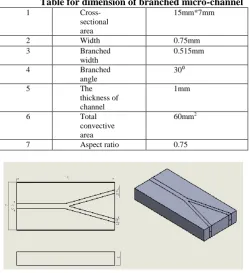
Using the aspect ratio of micro-channel (height or width) is 1:1 for straight channel and the aspect ratio of branched channel is 0.75/1. The working test piece is made of copper metals. The channels are grooving in the copper test piece plate. Copper is used because it gives more or better heat transfer enhancement in
International Journal of Innovative Technology and Exploring Engineering (IJITEE) ISSN: 2278-3075, Volume-9 Issue-2, December 2019
[image:3.595.45.296.145.419.2] [image:3.595.323.541.466.640.2]heat. Copper as ability to expand the equal heat transfer for all the surface of channel. It can dissipate the lager amount of heat when fluid flow in the micro-channels. The recent issue is found in heat transfer in the electronic cooling system by flow boiling. The melting point of copper is 1357.77 k, boiling point 2835 k and the density is near respect to 8.96 g/cm³.
Table for dimension of branched micro-channel
1
Cross-sectional area
15mm*7mm
2 Width 0.75mm
3 Branched
width
0.515mm
4 Branched
angle
30⁰
5 The
thickness of channel
1mm
6 Total
convective area
60mm2
7 Aspect ratio 0.75
Figure2. Design of branched channels
Table for dimensions of straight channel
1
Cross-sectional
area 7mm*10mm
2
The thickness of
channel 0.515
3
Depth of
channel 0.515
4
Total convective
area 60mm2
5 Aspect ratio 1
6
Total number of
channel 4
Figure3. Assembly of straight channels
I. Calculations steps are taken into account as follows
I. Hydraulic diameter
= 2ab/a+b a = height, b = width II. Discharge = A*V Area = π r² III. Velocity = discharge / area IV. Heat transfer coefficient
Q = hA(T₂-T₁) V. Heat flux
q = dQ/dA VI. Heat transfer coefficient
H = q/Δt
ΔT = temperature difference VII. Renold number
Re = inertia force / viscous force = ρvD/µ
VIII. Nusselt number
Nu = hl/k IX. Temperature difference (∆T)
Where, ∆T = Tw - Tavg X. Average temperature
Tavg= T1+T2
IV. RESULTS
A. Variation with heat transfer coefficient with flow rate
Experimental analysis has been worked at constant steady wattages i.e. 90 w at four different 2, 4, 6, and 8 LPH. Based on the experimental result, it is concluded that the heat transfer coefficient of branched and straight channel of different aspect ratio 0.75 and 1. Heat transfer coefficient is higher in the straight channel as compared to branched channel. Variation of heat transfer coefficient with flow rate, shown in the figure 4.
2 3 4 5 6 7 8
6000 8000 10000 12000 14000 16000 18000 Branched Straight
Flow rate (LPH)
H e a t tra n sf e r co e ff ici e n t 8000 10000 12000 14000 16000 18000 20000 H e a t t ra n sf e r co e ffi ci e n t
Figure4. Heat transfer coefficients vs flow rate
B. Variation of temperature drop with change in
axial length for branched channel
Experimental analyses have been worked at steady heat flux for both different aspect ratio of branched channel. Based on experimental results, it is concluded that temperature drop of branched channel aspect
with decrease in the temperature drop. Variation in the temperature drop with respect to axial length, shown in the figure 5, 6.
Figure5. Axial length vs Temperature drop for branched channel aspect ratio 1
Figure6.Temperature drop vs axial length for branched 0.75
C. Variation of temperature drop with change in
axial length for straight channel
Experimental analyses have been worked at steady heat flux for both different aspect ratio of straight channel. Based on experimental results, it is concluded that temperature drop of Straight channel aspect ratio 1.37 is greater than the straight aspect ratio 1. Variation in the temperature drop with respect to axial length, shown in the figure 7, 8.
Figure7. Axial length vs Temperature drop for straight channel aspect ratio 1.37
Figure8. Axial length vs temperature drop for straight channel aspect ratio 1
D. Variation of Nusselt no. change with axial length
for branched channel
Experimental analysis has been worked at steady heat flux for different aspect ratio of branched channel. Based on experimental results, it concluded that the Nusselt no. of branched channel is greater than straight channel. In this experiment found larger the Nusselt number larger heat transfer coefficient. Variation in Nusselt number with change to the axial length is shown in the figure no.9, 10.
Figure9. Axial length vs Nusselt for branched channel aspect ratio 1
Figure10. Axial length vs Nusselt no for branched channel aspect ratio 0.75
E. Variation Nusselt no. change with the axial
International Journal of Innovative Technology and Exploring Engineering (IJITEE) ISSN: 2278-3075, Volume-9 Issue-2, December 2019
Figure11. Axial length vs nusselt no for straight channel aspect ratio 1.37
Figure12. Axial length vs Nusselt no. for straight channel aspect ratio 1
F. Variation of velocity with change in axial length
for branched channel
Figure13. Axial length vs velocity Branched aspect ratio 1
Figure14. Axial length vs velocity for branched channel aspect ratio 0.75
V. CONCLUSION
In this experiment investigate the power supply of 90w to change in heat transfer coefficient 8% to 18%. We are found the maximum temperature drop for straight channel is 11⁰c. The temperature drop play also plays a significant role in heat transfer characteristics of micro channels. The velocity
of the channel decrease with the increase of axial length. The aspect ratio play an important role to heat transfer, it means we are found lower the aspect ratio greater temperature drop. In this experiment we are using the aspect ratio of branched (1 or 0.75) and for straight channel (1 or 1.37) .This experiment is perform two different areas like 60mm2 and 47mm2. At last we are found a conclusion according to this experiment temperature drop is dependent on the convective area. It means lower the convective area and larger the temperature drop. The Nusselt number decreases parallelly as well as decrease the flow rate or temperature drops. This investigation found maximum temperature drop found experimentally in straight channel as compared to branched channel. Different-different aspect ratio used for branched channel and straight channel. And convective area of both the channel is same as approximately 60mm2 and 47mm2
REFRENCES
1. Tuckerman, D. B. and Pease, R. F. W., “High-performance heat sinking for VLSI,” IEEE Electron Dev. Lett., Vol. EDL-2, No. 5, pp. 126-129, 1981.
2. I. Papautsky, J. Brazzle, T. Ameel, and A. B. Frazier, “Laminar fluid behavior in microchannels using micropolar fluid theory,” Sensors and Actuators A, vol. 73, pp. 101-108, 1999.
3. Dehghan M, Mirzaei M, Mohammadzadeh A. Numerical formulation and 480 simulations of non-Newtonian magnetic fluid flow in the boundary layer of a 481 stretching sheet. J Model Eng 2013;11 (34):73–82.
4. X.F. Peng, B.X. Wang, Forced convection and flow boiling heat transfer for liquid flowing through microchannels, Int. J. Heat Transf. 36 (1993) 3421-3427.
5. Poh Singh Lee, S.V. Garimella, D. Liu, Investigation of heat transfer in rectangular microchannels, Int. J. Heat Mass Transf. 48 (2005) 1688-1704.
6. T. Popescu, Microchannel heat exchanger – Constructive and functional characteristics (in Romanian), Master in Mechanical Engineering Dissertation, University “Politehnica” of Bucharest, Bucharest, February 2007.
7. R.k. Shah and A.L.L. London, Laminar flow forced convection in ducts, Academic Press, NewYork , 1978.
8. P.Wu and W. A. Little, “Measurement of friction factors for the flow gases in very fine channel used for microminiature Joule- Thomson refrigerator,” Cryogenics, No. 5,pp.
9. X.F.Peng and B.X. wang, “Liquid flow and heat transfer in microchannels with/without phase change,” in proc.10th
International Heat Transfer Conference, Brighton, UK, Aug 14-18.