Int. J. Electrochem. Sci., 7 (2012) 8205 - 8212
International Journal of
ELECTROCHEMICAL
SCIENCE
www.electrochemsci.org
Short Communication
High Sensitivity Multiple Gases Sensor With an Array of
Micro-ring Resonators
Honggui Deng1, Bingchu Yang1,2, Zhou Chen1, Xuemei Xu1, Jiafeng Ding1, and Shaohua Tao1,2,*
1
School of Physics and Electronics, Central South University, Changsha, China 410083 2
Institute of Super Microstructure and Ultrafast Process, School of Physics and Electronics, Central South University, Changsha, China 410083
*E-mail: [email protected]
Received: 13 July 2012 / Accepted: 3 August 2012 / Published: 1 September 2012
A gas sensing system comprising an array of photonic wire waveguide-based ring resonators is proposed. As a ring resonator propagates resonant lights only, parameters of the resonator can be deliberately designed such that a resonant light of the resonator is tuned with an absorption spectral line of a gas. Thus, an array of ring resonators can be used to select a series of resonant lights tuned with spectral lines of multiple gases. Simulation results show that three gases, CH4, CO2, and HF for example, are simultaneously detected by the system with high sensitivity. The gas sensing system can be fabricated as compact and portable with current fabrication technology.
Keywords: Optical sensors; Gas detectors; Sensor systems and applications; Optoelectronic and photonic sensors
1. INTRODUCTION
absorption lights of the gas. Thus, a gas can be identified by an absorption spectral line which is not overlapped with any of other gases. Concentration level of a gas can be measured based on optical power attenuation of a spectral light passing through the target gas. Most optical-based gas sensors are based on optical absorption spectroscopy, which can be realized by methods such as non-dispersive infrared (NDIR) [7], optical filtering [8], Fourier-transform infrared (FTIR) [9], and etc. NDIR and optical filtering methods adopt very narrow wavelength-band lasers or optical filters to select absorption lines of a gas for detection. Laser sources such as tunable diode lasers [10,11] and quantum cascade lasers [12] are commonly used. As NDIR and optical filtering techniques usually tune light emissions with a single absorption line of a target gas, they are rarely applied to measure components of multiple gases simultaneously. FTIR method uses a broad-band laser source and analyzes absorption spectra of the interest with an interferometer. The measured absorbance can be used to determine constituents of multiple gases qualitatively and quantitatively. Although the FTIR method is highly accurate and efficient in detecting gas constituents, the involved optical systems are usually expensive and bulky. In this paper we propose a gas sensing technique that can detect multiple gases fast and reliably. The gas sensing system is also compact and portable as most of the components of the system can be integrated in a chip with current semiconductor fabrication technology. Although photonic micro-ring resonators have been used as biosensors [13-15], all the referred methods utilized micro-ring resonators as sensing device to detect surrounding bio-samples directly. In our method, the photonic micro-ring resonator arrays are functioned as wavelength filtering device. Light attenuations of different wavelengths filtered by the array of wire-waveguide based micro-ring resonators are detected by photodetectors. The respective light attenuations of the gases are used to simultaneously detect concentration levels of the constituents of the mixed gases with high sensitivity.
2. DESIGN AND PRINCIPLE OF THE PROPOSED SYSTEM
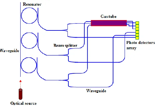
between the transmitting lights and gases stands alone from the integrated chip, optical fibers have to be used to couple lights into and out of the gas tube.
Figure 1. Schematic layout of the gas sensing system. Note that the components are not drawn to scale.
It is well known that resonant wavelengths in a photonic micro-ring resonator can be determined by the following equation,
R m
n2 , (1)
where n represents effective index of the wire waveguide of the ring resonator, R is radius of the ring, λ is resonant wavelength, and m (=1,2,3…) is the order of the resonant modes. Hence, by selecting radius and materials of a ring resonator we can control wavelength of a resonant light to overlap with the center of a spectral line of a gas. All the radii of micro-ring resonators in the array can be selected in a similar way such that output lights of the resonators are respectively tuned with specified spectral lines of multiple gases. As light in the coupling waveguide of a resonator is split into two by a beam splitter, one arm of the light passing through the gas tube will be attenuated owing to the spectral absorption and the other arm of the light reaching to a photodetector directly will be used as reference for optical power measurement. All the photodetectors are arranged in an array so that they can be fabricated with the same process. From Lambert-Beer law we can obtain concentration level of a target gas by detecting optical power attenuation ratio of the light with the following equation [18],
kT
L v v S
P C I
I 0exp line ( 0)
, (2)
where I is the intensity of light after passing through a gas of interest, I0 is the intensity of light
[image:3.596.180.433.134.303.2]
temperature T, k is Boltzmann’s constant, Sline is spectral line intensity of the gas, (vv0) is the
spectral line shape function at frequencyv, v0 is the central frequency of the spectral line, and L is length of light propagated in the gas. Sline and (vv0) are characteristic parameters of the gas and
can be referred to Hitran database [19]. Thus, if I and I0 are measured, we can determine concentration
level of the target gas with Eq. (2). In this paper concentration of a gas will be expressed in parts-per-million (PPM) by volume.
3. SIMULATION RESULTS
In our simulations we choose three gases, CO2, CH4, and HF, as an example for detection as the gases are widely found in atmospheres, coal tunnels, chemical plants, and semiconductor foundries. The criteria selecting detecting spectral lines of the gases are that, the spectral lines fall within wavelength band of optical source of the gas sensing system, are strong enough for detecting, and are not interfered by strong spectral lines from other gases. Spectral lines 6046.9647 cm-1, 7823.8212 cm-1, and 4989.9715 cm-1 of CH4, HF, and CO2 are chosen, respectively, as these lines have high spectral line intensities and are not interfered by spectral lines of the other gases. Figure (2) shows spectral lines of CO2, CH4, and HF in the range from 5000 cm-1 to 8000 cm-1. The vertical axis in the left shows line intensities of CO2 and CH4, which are in the magnitudes of 10-21 cm-1/(molecule×cm-2), and the vertical axis in the right shows line intensities of HF, which are in the magnitude of 10-20 cm-1/( molecule×cm-2
). We can observe from Fig. 2 that every cluster of spectral lines of a gas is several orders stronger than the surrounding spectral lines of the other gases. Hence, absorption in the band of clustered spectral lines of a gas can be regarded as caused by the gas only. The line intensities of the chosen spectral lines of CH4, HF, and CO2 are 1.335×10⁻²¹ cm-1/(molecule×cm-2), 7.693×10⁻²⁰ cm-1/( molecule×cm-2), and 1.287×10⁻²¹
cm-1/( molecule×cm-2), which are illustrated in Fig. 2, respectively.
[image:4.596.184.407.523.695.2]
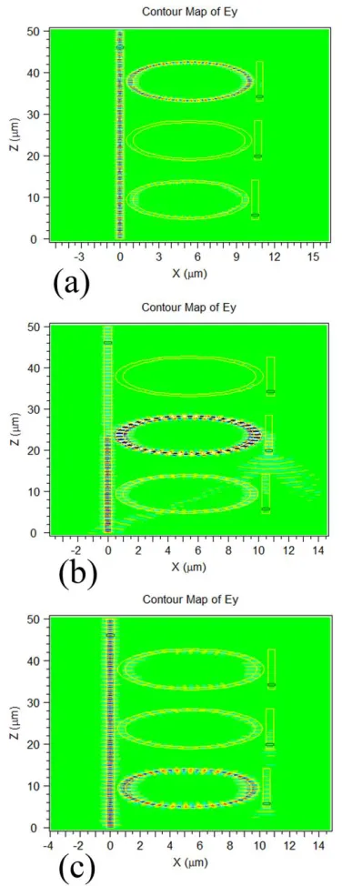
The micro-ring resonators can be constructed on silicon-on-insulator (SOI) materials system, which is compatible with the current silicon micro-fabrication technology. Waveguide material of the resonators is crystalline silicon with a thickness of 220 nm. Width of the waveguides is 500 nm. The waveguide supports propagation of fundamental light modes only. Coupling gaps between waveguides and resonators are 250 nm wide. Radii of the three resonators are calculated as 4740 nm, 4848 nm, and 4916 nm, respectively. Thus, resonant lights of the three resonators are respectively tuned with the corresponding selected spectral lines of the three gases. In the simulations, owing to huge computation of a three-dimensional finite-difference time-domain (FDTD) method for this system, we use two-dimensional FDTD method from a commercial software package (RSOFT) to simulate light propagation in the resonators instead. Calculated effective index based on the 3D waveguide is used in the 2D FDTD simulations. Propagations and couplings of transverse electric mode of light in the ring resonator systems are shown in Fig. 3, where (a) the input light of the ring arrays is at wavelength of 1.2781 um and the ring of radius of 4916 nm resonates most strongly, (b) at wavelength of 1.6537 um and the ring of radius of 4848 nm resonates most strongly, and (c) at wavelength of 2.004 um and the ring of radius of 4740 nm resonates most strongly. It can be observed that the input lights in the resonator arrays are chosen as identical to the above selected spectral lines of HF, CH4, and CO2, respectively. Hence, with a broadband optical source, multiple resonators can be tailored to resonate with respective spectral lines of multiple gases. Resonant lights from the ring resonators pass through the gas tube and will be attenuated by the respective gases according to Beer’s law. Except for selected resonant lights, other resonant lights of the ring resonators are not tuned with strong absorption lines of the gases and the resultant light attenuations will be negligible. Thus, lights coupled from the three resonators can be respectively used to detect three different gases simultaneously.
estimation. In this case we calculate the line shape functions using the center wavelengths of the spectral lines only.
Figure 3. Light propagations with input lights at wavelengths of (a) 1.2781 um, (b) 1.6537 um, and (c) 2.004 um.
[image:6.596.203.391.129.616.2]
dynamically. To increase detecting resolution of the system, we need select higher intensity spectral lines of the gases, a longer gas tube such as a cavity that can provide a path length of several kilometers in a small volume cell [5], and photodetectors with higher sensitivity.
4. CONCLUSION
A gas sensing system based on an array of photonic wire waveguide-based micro-ring resonators has been proposed. Resonant lights of the ring resonators are deliberately tuned with respective absorption spectral lines of different gases. Thus, multiple gases in a mixture can be simultaneously identified from the characteristic spectral line absorptions of light. Simulation results have shown that the concentration levels of the gases can be measured at PPM scale. The gas sensing system would be useful in the applications such as gas monitoring of industry productions, air quality analysis, environmental pollution gases detection, and so on.
ACKNOWLEDGEMENTS
This work was financially supported by Natural Science Foundation of China (Grant Nos. 61172047 and 61178017) and Hunan Provincial Natural Science Foundation of China (Grant No. 11JJ2039) and Graduate Education Reform Project of Central South University (Grant Nos. 2011jg01 and 2011jg46).
References
1. N. Yamazoe and N. Miura, Sensors and Actuators B, 20(1994) 95–102. 2. P. Werle, R. Mücke and F. Slemr, Appl. Phy. B, 57(1993)131–139.
3. P. Werle, F. Slemr, K. Maurer, R. Kormann, R. Mücke and B. Jänker, Opt. Lasers in Eng., 37(2002) 101-114.
4. S. Schilt, L. Thevenaz, and P. Robert, Appl. Opt., 42(2003) 6728-6738. 5. G. N. Rao and A. Karpf, Appl. Opt., 50(2011)1915-1924.
6. D. Weidmann, A. A. Kosterev, F. K. Tittel, N. Ryan and D. McDonald, Opt. Lett., 29(2004)1837-1839,.
7. J. Mayrwöger, C. Mitterer, W. Reichl, C. Krutzler and B. Jakoby, Proc. SPIE, 8066(2011) 80660K. 8. A. J. McGettrick, K. Duffin, W. Johnstone, G. Stewart, and D. G. Moodie, J. Lightwave Technol.,
26(2008)432-440.
9. D. Briand, O. Manzardo, J. Hildenbrand, J. Wöllenstein and N.F. de Rooij, Proceedings of IEEE Sensors Conference Atlanta, (2007)1364–1367.
10. M. E. Webber, R. Claps, F. V. Englich, F. K. Tittel, J. B. Jeffries and R. K. Hanson, Appl. Opt., 40(2001)4395-4403.
11. M. B. Frish, R. T. Wainner, B. D. Green, M. C. Laderer and M. G. Allen, Proc. SPIE, 6010(2005) 86-94.
12. G. N. Rao and A. Karpf, Appl. Opt., 50(2011) A100–A115.
13. A. L. Washburn, L. C. Gunn and R. C. Bailey, Anal. Chem., 81(2009) 9499–9506.
14. Adam L. Washburn, Matthew S. Luchansky, Adrienne L. Bowman and Ryan C. Bailey, Anal. Chem., 82(2010)69–72.
16. Q. Xu, B. Schmidt, J. Shakya and M. Lipson, Opt. Express, 14(2006) 9431-9435.
17. S. H. Tao, Q. Fang, J. F. Song, M. B. Yu, G. Q. Lo and D. L. Kwong, Opt. Express, 16(2008) 21456-21461.
18. L. L. Gordley, B. T. Marshal and D. A. Chu, J. Quant. Spectrosc. Radiat. Transfer, 52(1994)563-580.
19. L.S. Rothman, I.E. Gordon, A. Barbe, D.Chris Benner, P.F. Bernath, M. Birk, V. Boudon, L.R. Brown, A. Campargue, J.-P. Champion, K. Chance, L.H. Coudert, V. Dana, V.M. Devi, S. Fally, J.-M. Flaud, R.R. Gamache, A. Goldman, D. Jacquemart, I. Kleiner, et al., J. of Quant. Spectrosc. Radiat. Transfer, 110(2009)533-572.
20. J. Niehusmann, A. Vörckel, P. H. Bolivar, T. Wahlbrink, W. Henschel and H. Kurz, Opt. Lett., 29(2004)2861-2863.