NUMERICAL INVESTIGATION OF NANOFLUID FLOW AND HEAT TRANSFER INSIDE A MICROCHANNEL
MUHAMMAD SYAFIQ BIN MD RADZI
This report is submitted in fulfilment of the requirement for the degree of Bachelor of Mechanical Engineering
Faculty of Mechanical Engineering
UNIVERSITI TEKNIKAL MALAYSIA MELAKA
DECLARATION
I declare that this project report entitled “Numerical investigation of nanofluid flows and heat transfer inside a microchannel” is the result of my own work except as cited in the references
Signature : ……….
Name : ……….
APPROVAL
I hereby declare that I have read this project and in my opinion this project is sufficient in terms of scope and quality for the award of the degree of Bachelor of Mechanical Engineering
(with Honours).
Signature : ………
Name of supervisor : ……….
i
ABSTRACT
ii
ABSTRAK
Mikrosaluran banyak digunakan dalam industri mikro-elektronik dalam semasa ke semasa untuk mencapai peralatan tahan panas terendah. Objektif kajian ini adalah untuk mengaplikasi aliran cecair alumina dengan hubungkait pada corak kelajuan yang dihasilkan dalam kajian. Dalam kajian ini, nanofluid alumina, 𝑨𝒍𝟐𝑶𝟑 dengan kelikatan
iii
ACKNOWLEDGEMENT
The completion of this Final Year Project could not have been possible without the assistance and participation of many people whose names may not all be written. I am thankful for their aspiring guidance, invaluable constructive criticism and friendly advice during the project work. Their contributions are sincerely appreciated and gratefully acknowledge.
Among others, I would like to express my sincere gratitude to my final year project supervisor, Dr Ernie Binti Mat Tokit, whose contribution in giving encouragement and suggestion, helped me coordinate my project especially in writing this report. I am grateful and honoured to her for all the knowledge, wisdom and experience she shared during my studies.
iv
Contents
ABSTRACT ... i
ABSTRAK ... ii
ACKNOWLEDGEMENT... iii
LIST OF FIGURES ... vi
LIST OF TABLES ... vii
LIST OF ABBREVIATIONS ... viii
LIST OF SYMBOL ... ix
CHAPTER 1 ... 1
Introduction ... 1
1.1 Background of Study ... 1
1.2 Problem Statement ... 3
1.3 Objectives ... 3
1.4 Scope of Project... 3
1.5 General Methodology ... 4
CHAPTER 2 ... 5
Literature Review ... 5
2.1 Introduction ... 5
2.2 Nanofluid Characteristics ... 5
2.3 Reynolds number and its significance. ... 6
2.4 Factors affecting fluid flow of nanofluid... 7
CHAPTER 3 ... 11
Methodology ... 11
3.1 Introduction ... 11
3.2 3D Design Domain ... 13
3.3 3D Modelling Mesh Discretization ... 13
3.4 Boundary Conditions ... 15
3.5 Thermal properties ... 17
CHAPTER 4 ... 18
Results ... 18
4.1 Introduction ... 18
4.2 Mesh Independence Test ... 18
4.3 Validation ... 20
4.4 Velocity Profile ... 22
v
4.6 Heat Flux ... 30
4.7 Nusselt Number ... 32
CHAPTER 5 ... 33
Conclusion ... 33
5.1 Introduction ... 33
5.2 Conclusion ... 33
vi
LIST OF FIGURES
Figure Title Page
1.0 Fluid flow varies along contact geometry 13
3.1 General methodology done in present study 27
3.2 Schematic of rectangular microchannel unit cell 28
3.3 Meshed domain viewed from top 29
3.4 Meshed domain viewed form the inlet 29
3.5 Dimension of unit cell of microchannel 30
3.6 Properties of nanofluid 33
4.1 Nusselt number to different meshed sizes 35
4.2 Mesh independence test for different meshed sizes 36
4.3 Comparison of average Nusselt number at Re=140 37
4.4 Cross-sectional planes of fluid flows 39
4.5 Fluid velocity at the middle plane of fluid channel 41
4.6a Velocity profiles of fluid flows at Re=140 41
vii
LIST OF TABLES
Table Title Page
2.1 Result of critical Re determined by previous researchers 24
3.1 Boundary-type specifications for domain 31
3.2 Continuum type of specifications 31
4.1 Distance of each planes along the channel 39
viii
LIST OF ABBREVIATIONS
CFD Computer Fluid Dynamic
ix
LIST OF SYMBOL
𝐴𝑐 = Area of cross section, 𝑚2
a = Width of the entrance of fluid channel, m b = Height of the entrance of fluid channel, m 𝐷ℎ = Hydraulic diameter, 𝜇𝑚 (𝐷ℎ=4A/P) P = Perimeter of entrance of fluid channel, m k = Thermal conductivity, W/m.K
𝐿𝑐ℎ = Length of the channel, m
𝐻𝑡 = Height of a single reentrant cavity, m N = Number of channel
Nu = Nusselt number Pa = Static pressure, Pa 𝑞′′ = Heat flux, W/𝑐𝑚2 Re = Reynolds number T = Temperature, K u = Fluid velocity, m/s
SUBSCRIPT nf = Nanofluid
1 CHAPTER 1
Introduction
1.1 Background of Study
Fluid flow in micro-passages such microchannel in current studies have developed to meet the demand for thermal-hydraulic control of microsystem. The research on microsystem analysis has developed from time to time in achieving low thermal resistance in micro-electronics industry.
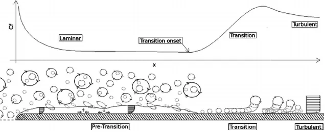
[image:13.595.148.466.512.643.2]Fluid flow in general can be characterized to three different stages which are laminar, transition and turbulent. The movement of adjacent fluid particles in highly ordered motion and smooth streamlines shows the fluid are in laminar motion whereas turbulent can be characterized by velocity fluctuations and highly disordered motion of fluid flow. The transition from laminar to turbulent flow is unsteady and difficult to predict, it happens over some region where fluid flow fluctuates between laminar and turbulent before it becomes fully develop region (Cengel & Cimbala, 2014).
Figure 1.0 Fluid flow varies along contact geometry (Coronella, 2008)
2 turbulent, the Reynolds number at that point is called critical Reynolds number (Osborne & Incropera, 1985).
It is better to have an accurate values of Reynolds number in determining the flow region of liquid flows as studied made by (Cengel & Cimbala, 2014) in macro-scale study. For macroscale study, the Reynolds number in transition from laminar to turbulent flow under most practical conditions is in the range of 0≤ 𝑅𝑒 ≤ 4000 for liquid flow inside macrochannel. That is,
Re ≤ 2000, laminar flow 2000 ≤ 𝑅𝑒 ≤ 4000, transitional flow
Re ≥ 4000, turbulent flow
The critical Reynolds number at which the flow become turbulent is different for different geometries and flow conditions. Avoiding flow disturbances and pipe vibrations in such carefully controlled laboratory experiments could maintain the Reynolds numbers.
Microchannels are defined as flow passages that have hydraulic diameters in the range of 10 to 200 micrometers. The evolution of microchannel have developed to several decades of improvements and received considerable attention in major application areas, such as advanced heat sink designs and micro fuel cell system. The development of understanding the fluid flow in microchannel is essential for the optimum design and effective operation of the microsystem. In this study also, the flow of the fluid inside the microchannel is analysed numerically with dimension of the microchannel for the fluid flows are 57 μm x 180 μm with length of 10mm. Two solid boundaries are separated with walls and fluid flows of the microchannel.
3 1.2 Problem Statement
Reynolds number is very significant in nanofluid microchannel flows to determine the flow and heat analysis throughout the micro-scale system. However, the applicability of Reynolds number in micro-scale system is still under investigation whether it is usable for micro-scale system or not. Hence, this study is done to investigate the Reynolds number in nanofluid-microchannel flow together with the applicable of this Reynolds number range for macro-scale channel to the micro-scale channel.
1.3 Objectives
There are two main objectives in this study which are:
1. To simulate the nanofluid flow at various Reynolds number.
2. To investigate the velocity profile of nanofluid flow at various Reynolds number.
1.4 Scope of Project
The scopes of this project are:
1. The microchannel is rectangular in shaped with hydraulic diameters maximized to 200𝜇𝑚.
2. Reynolds number of 140 – 500 are investigated in the studies.
3. Alumina nanofluid, 𝐴𝑙2𝑂3 with kinematic viscosity of 0.001028 kg/𝑚𝑠−1 and concentration of 1% as the working fluid used in the study.
4
1.5 General Methodology
As to achieve good computational fluid dynamics results, the steps below are to be followed accordingly.
1. Literature review
Journals, articles, or any materials regarding the project will be reviewed.
2. Pre-processing (Designing)
Fluid flows in turbulent and the fluctuation of critical Reynolds number will be defined and determined through the analysis of research. The velocity profile of nanofluid flow at various Reynolds number will be identified through designing of the microchannel at the operating condition.
3. Solver (Mesh Generation)
The design of the microsystem is decomposed into cells with structured quadrilateral geometry specified to the design proposed. This discretization process acquires good meshing size with correct estimation of spatial derivatives to obtain good meshing result.
4. Post-processing (Numerical)
Velocity profile of nanofluid flows is analysed through Fluent 6.1 with generated meshed volume of microchannel.
5. Validation
5 CHAPTER 2
Literature Review
2.1 Introduction
This literature review will be focussing on the nanofluid flows inside microchannel. The objectives of this study are to identify velocity profile and to simulate nanofluid flow inside microchannel. In this chapter, previous studies that are related to nanofluid flows in microchannel are reviewed. The findings of this studies are studied and summarized in the form of tables and figures. This chapter is separated into three parts which are nanofluid characteristics, significance of nanofluids in relation to Reynolds number and factors affecting the nanofluid flows.
2.2 Nanofluid Characteristics
Several scholars have taken numerous studies about the nanofluid over centuries. At present, water and refrigerants are commonly used as working fluids inside microchannel, the mixture of conventional fluids is proposed with the use of nanoparticles (1-100 nm in diameter) to improve the heat transfer performance of conventional fluids by enhancing thermal conductivity inside the microchannel. The use of nanofluids have proved to be a very effective way for cooling systems inside microchannel due to nanoparticle separation to the base fluid. It has been proved that nanofluids have better heat transfer performance than the base liquid and a good substitutional for working fluids inside microchannel (H. Zhang, Shao, Xu, & Tian, 2013).
6 32% rather than distilled water at a volume fraction of 1.8% volume percent without major friction loss.
The study of nanofluid flow characteristics of low Reynolds number around a heated circular cylinder are studied by (Vegad, Satadia, Pradip, Chirag, & Bhargav, 2014) which resulted to increment of local Nusselt number over cylinder surface in nanoparticle fraction as well as increment of nanofluids flow strength. The study proved that local heat flux drops along cylinder wall while nanoparticles fraction increased together with Reynolds number along the cylinder wall until the outlet.
2.3 Reynolds number and its significance.
7 Investigation of three dimensional heat transfer in silicon microchannel by (Qu & Mudawar, 2002) proved that the temperature rise along the flow direction in the solid and fluid can be approximated as linear. The length of the flows developing region are affected by increasing Reynolds number to 1400 which fully developed flow may not be achieved as Reynolds number are affected by the thermal conductivity as it approaching to the channel outlet. Measured temperature distribution is well predicted by CFD prediction on validity of conventional theory and numerical solution of laminar Navier-Stokes equations as correlations used in comparisons.
2.4 Factors affecting fluid flow of nanofluid
(Peiyi & Little, 1983) has reported that there are many factors in which affecting the fluid flow and at the same time affecting the value of the friction factor in microchannel. Surface roughness is one of the factors that affects the fluid flow from transition to turbulent mostly by increasing of drag coefficients in turbulent flow in microscale channel. In this case, significant roughness is presented but friction factors measured in smooth channel agreed with macroscale theory -in rectangular microchannel. Thus, making the friction factor too small that it can be negliable in this microchannel.
There are two parameters that essential to Reynolds number in nanofluid studies whereas there are the inlet velocity and the kinematic viscosity of nanofluid which the Reynolds number are depended on. To keep the Reynolds number constant for heat transfer enhancement in the microchannel, the increment of inlet velocity has a major role in reaching constant Reynolds same as important of increment of nanoparticles volume fraction of nanofluid (Akbarinia, Abdolzadeh, & Laur, 2011).
8 performed using spherical gold nanoparticles of (10, 50 and 100 nm), volumetric concentration of (0.00064% - 0.0052%) and flow rate of (100 – 140 μm/min) on the nanofluid performance of 70 μm x 50 μm rectangular copper microchannels in determining the surfactant effect.
Considering particle migration of nanofluid, particle clustering and particle interactions with the wall, the nanofluid flow are affected due to possible heat transfer enhancement with more complex nanoparticle-based fluid interactions as well as different preparation methods in preparing nanofluid that lead to inconsistencies in research projects on nanofluids. The study of particle migration on nanofluid is performed (Bahiraei, 2016) by taking Brownian motion and viscosity of nanofluids into account in stabilizing nanoparticle along the microchannel.
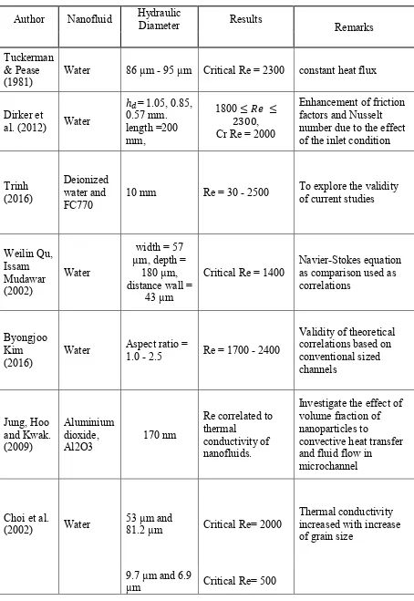
9 Table 2.1 Result of critical Re determined by previous researchers.
Author Nanofluid Hydraulic Diameter Results
Remarks
Tuckerman & Pease
(1981) Water 86 µm - 95 µm Critical Re = 2300 constant heat flux
Dirker et
al. (2012) Water
ℎ𝑑= 1.05, 0.85, 0.57 mm. length =200 mm,
1800 ≤ 𝑅𝑒 ≤ 2300, Cr Re = 2000
Enhancement of friction factors and Nusselt number due to the effect of the inlet condition
Trinh (2016)
Deionized water and
FC770 10 mm Re = 30 - 2500
To explore the validity of current studies
Weilin Qu, Issam Mudawar (2002)
Water
width = 57 µm, depth =
180 µm, distance wall =
43 µm
Critical Re = 1400 Navier-Stokes equation as comparison used as correlations
Byongjoo Kim
(2016) Water
Aspect ratio =
1.0 - 2.5 Re = 1700 - 2400
Validity of theoretical correlations based on conventional sized channels Jung, Hoo and Kwak. (2009) Aluminium dioxide,
Al2O3 170 nm
Re correlated to thermal
conductivity of nanofluids.
Investigate the effect of volume fraction of nanoparticles to
convective heat transfer and fluid flow in
microchannel
Choi et al.
(2002) Water 53 µm and 81.2 µm Critical Re= 2000
Thermal conductivity increased with increase of grain size
10 Wu and
Little
(1983) Water
45.5 µm and
83.1 µm Re<1000 = laminar Glass and silicon channels
Re>3000=turbulent
900-3000=transition
Hegab et
al.(2002) R134a 112 µm to 210 µm Transition= 2000 to 4000 Aluminium Microchannel
Yu et al.
(2014) Methanol 57 µm - 267 µm Re = 50-850 Early laminar transition does not exist.
Zhang et
al. (2013) Nanofluids Al203 5.0 µm - 17.4 µm Re = 600 - 20000 Pr= 5.7 - 7.3, nusselt correlation to Pr number.
Judy et al.
(2002) Water 50 µm - 100 µm Critical Re = 2300
Adiabatic boundary condition for silica microchannel and single-phase flow
Methanol 15 µm - 150 µm
Isopropanol 75 µm - 125 µm
11 CHAPTER 3
Methodology
3.1 Introduction
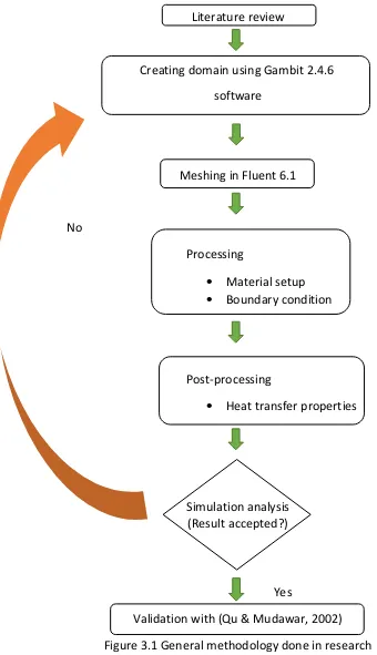
This chapter provides a detail description of the methodology or how this whole project proceeds. This chapter also focus on what kind of method being used to obtain the necessary data for velocity profile and nanofluid flow inside microchannel. As can be observe in the flow chart provided in Figure 3.1, the figure shows the step required to successfully achieve the aim of the study in finding critical Reynolds number of nanofluid in transition flows inside microchannel.
The microchannel is created in 3D domain using GAMBIT software. After successfully created the volume of 3D domain, the 3D domain is meshed throughout each surfaces of the volume by aligning the node number to correct estimation. This cells with structured quadrilateral geometry need to be designed closely to one another at the inlet and getting distant as it come out to the outlet which results to velocity profile and critical Reynolds of nanofluid in the microchannel.
12 The methodology of this project is summarized in the flow chart as shown in Figure 3.1.
Literature review
Creating domain using Gambit 2.4.6
software
Meshing in Fluent 6.1
No
Processing
• Material setup
• Boundary condition
Post-processing
• Heat transfer properties
Simulation analysis (Result accepted?)
Yes
[image:24.595.83.423.106.697.2]Validation with (Qu & Mudawar, 2002)