Int. J. Electrochem. Sci., 11 (2016) 9625 – 9633, doi: 10.201964/2016.11.25
International Journal of
ELECTROCHEMICAL
SCIENCE
www.electrochemsci.org
Short Communication
Galvanic Corrosion Behavior of Aluminum Alloy (2219 and
ZL205A) Coupled to Carbon Fiber-Reinforced Epoxy
Composites
Shiwen Zou1,*, Yanxian Zhang2, Wen Xu1, Yingqi Wan2, Chang He2, Chaofang Dong2, Xiaogang Li2 1
Aerospace Research Institute of Materials and Processing Technology, Beijing 100076, China 2
Corrosion and Protection Center, Key Laboratory for Corrosion and Protection (MOE), University of Science and Technology Beijing, Beijing 100083, China
*
E-mail: [email protected]
Received: 8 May 2016 / Accepted: 1 September 2016 / Published: 10 October 2016
The galvanic corrosion behaviors between carbon fiber-reinforced epoxy composites (CFREC) and aluminum alloy (2219 and ZL205A) in 3.5 wt.% sodium chloride solutions were evaluated by laboratory electrochemical measurement. The corrosion morphology, products and galvanic currents of galvanic couples were measured. The results indicate that there were serious galvanic corrosion when these two kinds of materials were coupled for 10 hours in 3.5wt.% NaCl solution, corrosion pits and grooves can be clearly observed on both aluminum alloys; the galvanic current of 2219 is slightly higher than that of ZL205A which both decrease with time; the average galvanic current density of 2219 and ZL205A is 20.19μA·cm-2 and 16.08 μA·cm-2
respectively; as a result, two types of aluminum alloys are not allowed to contact with CFREC directly in hygrothermal salt spray environment.
Keywords: galvanic corrosion, carbon fiber-reinforced epoxy composites, aluminum alloy
1. INTRODUCTION
Military materials are deployed and used under varied and severe environmental conditions. The use of aluminum alloy and CFREC is desirable in the design and fabrication of equipment. Aluminum alloy ZL205A, produced by Liu et al.[8]in the 1970s and Aluminium alloy 2219 has been widely used in the aerospace and aviation industries as a main structural material for its excellent mechanical properties, stress corrosion resistance and good weldability[9-13]. However, Corrosion of aluminum alloy in corrosive environments could reduce the mechanical properties of components and lead to material failure. And when CFREC and the aluminum alloy are served as connection structure materials of launch vehicles and placed in humid ocean-atmosphere environment, there will be a significant electrical potential difference between them[14,15]. The potential difference will provide a stronger driving force for the dissolution of the aluminum alloy[16-19]. Consequently, these corrosion processes will reduce the degree of anastomosis between the two joints and the structural strength and sealing[20].
Although the danger of galvanic corrosion has been recognized generally, little work has been done to quantitatively measure the extent of corrosion of various galvanic couples, and use of such data as the basis for ranking of galvanic couples [21]. Therefore, to carry out deep and thorough research work on galvanic corrosion of aluminum alloy and CFREC couples means a lot not only in extending their applications on materials of launch vehicle, but also enriching electrochemical corrosion data and assessing their service life.
2. EXPERIMENTAL
2.1 Materials
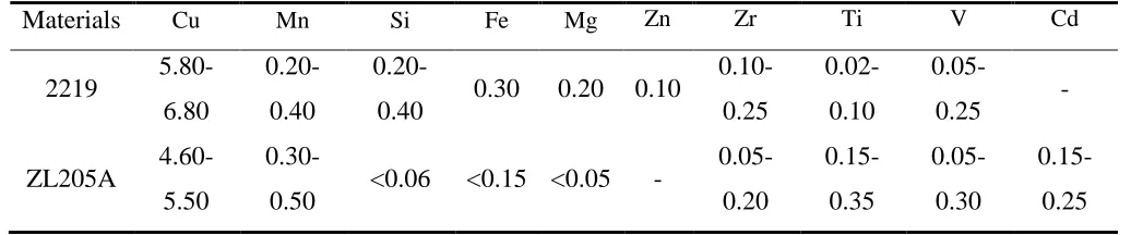
[image:2.596.40.558.613.721.2]The working electrodes used in this work were coupling samples, which were 2219 and ZL205A aluminum alloy as the anodic material and CFREC as the cathode material. CFREC was made of MT300/803, polyacrylonitrile based unidirectional woven carbon fiber reinforced epoxy composites, and the laminate was prepared with vacuum autoclave method. The element components of the two kinds of aluminum alloys are shown in Table 1.
Table 1. Chemical compositions (mass fraction in %)
Materials Cu Mn Si Fe Mg Zn Zr Ti V Cd
2219
5.80-6.80
0.20-0.40
0.20-0.40 0.30 0.20 0.10
0.10-0.25
0.02-0.10
0.05-0.25 -
ZL205A 4.60-5.50
0.30-0.50 <0.06 <0.15 <0.05 -
Samples of 2219, ZL205A aluminum alloys and CFREC were cut into 66 mm×15 mm×2 mm. In order to fix the sample, a small hole with a diameter of 3 mm was drilled at the top of the sample by 10 mm, as shown in Fig.1. The two kinds of materials were grounded with silicon carbide emery paper from 400 grit, 800 grit, 1200 grit until 2000 grit sequentially, then rinsed with alcohol and dried under cold air stream. The surfaces of samples were coated with silica gel that the bulk surface area of 14 cm2 was exposed to the corrosion test. Then the aluminum alloy and CFREC was coupled with 5 mm spacing between them.
Figure 1. Shapes of aluminum alloy and CFREC
2.2 Electrochemical measurement of galvanic corrosion
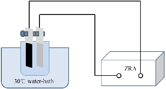
[image:3.596.166.430.206.369.2]The electrochemical cell was allowed to stabilize before performing the electrochemical measurements. For the galvanic corrosion measurements, the galvanic current density (Ig) was recorded simultaneously as a function of time using the ZRA (ZRA-2, Beijing Zhongfu Corrosion & Protection Co., Ltd) instrument and applying a zero potential against the galvanic cell (Fig. 2).The electrolyte used for electrochemical tests was aqueous 3.5% NaCl solution. All the measurements were carried out at a temperature of 30℃ in the air environment. Couples mentioned above were immersed in 500 ml electrolyte for 10 hours, and measured galvanic current every other 30 minutes.
[image:3.596.158.441.589.741.2]
Macro-morphologies of specimens before and after the electrochemical measurements were recorded by stereology microscope (KEYENCE VHX2000). Micro-morphologies and EDS of corrosion products on the specimens surfaces were recorded by FEI Quanta 250 environment scanning electron microscope with an electron-accelerated voltage of 20 keV.
3. RESULTS AND DISCUSSION
3.1 Corrosion morphology and corrosion products
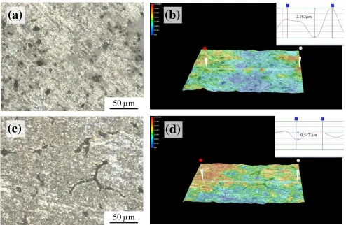
Fig.3 shows the surface morphologies in macro scale as well as the distribution of the etch-pits of two different aluminum alloys after they were coupled to CFREC for 10 hours in 3.5% NaCl solution. A severe selective corrosion occurred on the surface of two different aluminum alloys. The corrosion status of 2219 is more serious and the corrosion products are in the forms of pits, which are relatively uniform distributed.
Figure 3. Galvanic corrosion morphology (a) and 3D version (b) of 2219 and galvanic corrosion morphology (c) and 3D version (d) of ZL205A aluminum alloy coupled with CFREC
On the other hand, straight cracks can be seen on the surface of ZL205A aluminum alloy, which is relatively flat without obvious undulating deep pits. Such condition of surface is probably formed by the continual expansion and aggregation of the pits.
Fig.4 shows the surface morphologies microcosmically of two different aluminum alloys change with time from the immersion test lasting for 10 hours in 3.5% NaCl solution after they were
50 m
(c)
(a)
50 m
(b)
[image:4.596.49.543.301.623.2]
(b)
30 m
coupled with the CFREC. It can be seen that the corrosion products are incompact and irregular on the surface of two types of magnesium alloy, and cracks appeared around the corrosion products. Moreover, the corrosion products of 2219 aluminum alloy is more incompact than that of ZL205A aluminum alloy, which indicates that more serious corrosion occurred on 2219 aluminum alloy. In addition, EDS gives results about types and compositions of major elements of corrosion products: the main elements of the sample surface are O and Al, which means that the main corrosion products are aluminum oxide during the process of corrosion. Hernandez [22] found that when chloride ions are the only pollutants present in the aqueous solution, the corrosive attack results in the formation of a rather big number of corrosion pits. In this paper, there are more corrosion products due to the existence of CFREC.
Figure 4. Galvanic corrosion morphology and EDS results of corrosion products of 2219 (a) and ZL205A (b) aluminum alloy coupled with CFREC
3.2 Galvanic corrosion current-time curves
Fig.5 shows how the current of two different aluminum alloys change with time from the immersion test lasting for 10 hours in 3.5% NaCl solution after they were coupled with the CFREC. It can be seen that the CFREC/2219 and CFREC/ZL205A couplings starts with a high current density, and then the current density decreases with fluctuations rapidly within a few minutes. With the increase of testing time, the detected current of CFREC/2219 and CFREC/ZL205A are stabilized at
(a)
[image:5.596.71.508.266.608.2]
around 280 μA and 220 μA (area 13.9 cm2), respectively. The required time for CFREC/2219 and CFREC/ZL205A to reach the steady current densities is about 400 minutes.
0 200 400 600
200 250 300 350 400 450
i/
A
Time/min
1 2 3
0 200 400 600
150 200 250 300 350
i/
A
Time/min
1 2 3
Figure 5. Galvanic current-time curves of couples between 2219 (a), ZL205A(b) aluminum alloy and CFREC;
[image:6.596.141.441.130.614.2]
reasons could probably clarify the variation of the galvanic current density as follows. First, 2219 is wrought aluminum alloy, the massive grain boundary and inner-stress increase the corrosion susceptibility. Moreover, the reduced amounts of alloying elements such as copper, magnesium and zinc in ZL205A compared with 2219 (see Table 1) will decrease the corrosion susceptibility [26].
3.3 Evaluation of galvanic corrosion sensitivity
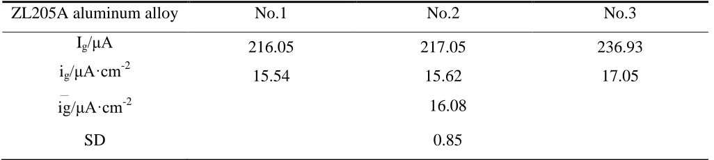
Calculate the average galvanic current(Ig) within 10 hours according to the galvanic current time curve; Calculate the galvanic current density (ig) according to the actual size of the galvanic anode; Calculate the average galvanic current density (ig
—
)and standard deviation (SD) according to the results of three sets of parallel test; Results are as follows in Table 2.
Table 2. (a) Galvanic current of CFREC/2219 couple
2219 aluminum alloy No.1 No.2 No.3
Ig/μA 327.29 256.19 258.29
ig/μA·cm-2 23.55 18.43 18.58
ig
—
/μA·cm-2 20.19
SD 2.91
Table 2. (b) Galvanic current of CFREC/ZL205A couple
ZL205A aluminum alloy No.1 No.2 No.3
Ig/μA 216.05 217.05 236.93
ig/μA·cm-2 15.54 15.62 17.05
ig
—
/μA·cm-2 16.08
SD 0.85
According to the relevant provisions of galvanic corrosion sensitivity of metal materials (level A: ig
—
≤0.3 μA·cm-2
; level B: 0.3<ig
—
≤1.0 μA·cm-2
; level C: 1.0<ig
—
≤3.0 μA·cm-2
; level D: 3.0<ig
—
≤10.0 μA·cm-2
; level E: ig
—
[image:7.596.43.554.328.444.2] [image:7.596.43.556.499.614.2]
results about the galvanic corrosion using Carbon Fiber Reinforced Plastic and LY12CZ couples. And probably due to different types of materials, galvanic current in our work is much higher.
4. CONCLUSIONS
(1) The surface morphology of 2219 and ZL205A aluminum alloy changes obviously after the galvanic corrosion when coupled to CFREC respectively. In particular, the surface roughness of aluminum alloy has increased and corrosion pits and grooves appears on the surface.
(2) Galvanic current density decreases with time on the whole. With the extension of time, the corrosion products on the surface of aluminum alloy have increased, serving as a protector for the substrate. Furthermore, the galvanic current of 2219 is slightly higher than that of ZL205A.
(3) The average galvanic current density of 2219 is 20.19μA·cm-2
while the average galvanic current density of ZL205A is 16.08 μA·cm-2
. As a result, two types of aluminum alloys are not allowed to contact with CFREC directly in hygrothermal salt spray environment.
ACKNOWLEDGEMENT
The authors would like to extend their gratitude towards University of Science and Technology Beijing for allowing this research to be carried out. The project was supported by Research Fund for corrosion and protection of metals (No.51222106).
References
1. A. Sayir, Journal of Materials Science, 39 (2004) 5995-6003.
2. H. Po-Hsiung, P. Chao-Chun, SU Ching-Iuan, and W. Chi-Hsian, Journal of Advanced Materials, 36 (2004) 35-38.
3. P. A. Schweitzer, Corrosion Engineering Handbook, Marcel Dekker, Inc,New Fork (1996) 4. Aviation establishment of China, Handbook of Composite Materials Structure, Aviation Industry
Press, Beijing (2001).
5. R. J. Wu, Composite Materials, Tianjin University Press, Tianjin (2000). 6. M.N. Alias, R. Brown, Corrosion Science, 35(1993)395-402.
7. C. Soutis, Progress in Aerospace Sciences, 41(2005)143-151.
8. Liu Bocao, Xiang Qiyao, Qian Jingxin, Aeronautical Materials, 5 (1978) 11-17.
9. Zhang Ming, Zhang Weiwen, Zhao Haidong, Transactions of Nonferrous Metals Society of China, 17 (3) (2007) 496-501.
10.J. P. Lokker, A. J. Bottger, W. G. Sloof , Acta Materialia, 49 (8) (2001) 1339-1349.
11.E. M. Elgallad, F. H. Samuel, A. M. Samuel, Journal of Materials Processing Technology, 210 (13) (2010) 1754-1766.
12.Chen Bangfeng, Jia Panjiang, Journal of Materials Engineering, 9 (2010) 1-6
13.G. V. Narayana, V. M. J. Sharma, V. Diwakar, Science & Technology of Welding & Joining, 9 (2) (2004) 121-130.
14.S. Palani, T. Hack, J. Deconinck, and H. Lohner, Corrosion Science, 78 (2014) 89-100.
15.F. Mansfeld, J. V. Kenkel, F. Mansfeld, J. Kenkel, Astm Special Technical Publication, 576 (1976) 20-47.
17.R. L. Miller, W. H. Hartt, R. P. Brown, Materials Performance, 15 (1976) 20-27.
18.T. F. A. Santos, G. C. Vasconcelos, W. A. D. Souza, and ML Costa, Materials & Design, 65 (2015) 780-788.
19.F. Bellucci, G. Capobianco, British Corrosion Journal, 24 (3) (1989) 219-221.
20.M. Bobby-Kannan, R. Raman, A. K. Mukhopadhyay, and V.S. Raja, Corrosion-Houston Tx-, 59(2003)881-889.
21.Subramanian, Palraj, Palanichamy, Journal of Marine Science & Application, 13 (2014) 230-236. 22.F.J. Hernandez, J.J. Santana, R.M. Souto, S. González1, J. Morales, International Journal of
Electrochemical Science, 6 (2011) 6567-6580.
23.Z. Liu, M. Curioni, P. Jamshidi, A. Walker, P. Prengnell, G. E. Thompson, P. Skeldon, Applied Surface Science, 314(2014) 233-240.
24.Robert Ireland, Luciana Arronche, Valeria La Saponara, Composites, 43 (2012) 183-194. 25.Z. Peng, X. Nie, Surface & Coatings Technology, 215 (2013) 85-89.
26.M. Abdulstaar, et al., Mater. Des. 57(0) 325-329.
27.Lu Feng, Zhang Xiaoyun, Tang Zhihui, Liu Ming, Journal of Chinese Society for Corrosion and Protection, 25(1) (2005) 39-42.