This is a repository copy of
The influence of material properties on the wear of abradable
materials
.
White Rose Research Online URL for this paper:
http://eprints.whiterose.ac.uk/98494/
Version: Accepted Version
Article:
Fois, N., Watson, M. and Marshall, M.B. (2017) The influence of material properties on the
wear of abradable materials. Proceedings of the Institution of Mechanical Engineers, Part
J: Journal of Engineering Tribology, 231 (2). pp. 240-253. ISSN 1350-6501
https://doi.org/10.1177/1350650116649528
eprints@whiterose.ac.uk https://eprints.whiterose.ac.uk/ Reuse
Unless indicated otherwise, fulltext items are protected by copyright with all rights reserved. The copyright exception in section 29 of the Copyright, Designs and Patents Act 1988 allows the making of a single copy solely for the purpose of non-commercial research or private study within the limits of fair dealing. The publisher or other rights-holder may allow further reproduction and re-use of this version - refer to the White Rose Research Online record for this item. Where records identify the publisher as the copyright holder, users can verify any specific terms of use on the publisher’s website.
Takedown
If you consider content in White Rose Research Online to be in breach of UK law, please notify us by
The Influence of material properties on
the Wear of Abradable Materials
N. Fois, M. Watson, M.B. Marshall
Department of Mechanical Engineering, The University of Sheffield, Mappin Building, Mappin Street, Sheffield, S1 3JD, UK.
Abstract
In aero-engines it is possible for the blades of the compressor, turbine or fan to incur into their casings. At these interfaces a lining of composite abradable material is used to limit damage to components and thereby sustain the efficiency and longevity of the engine as a whole. These composite materials must have good abradability and erosion resistance. Previously, the wear mechanisms at the contact between the blade and the coating have been characterized using stroboscopic imaging and force measurement on a scaled test-rig platform.
This work is focused on the characterization of the wear mechanism for two different of abradable lining. The established stroboscopic imaging technique and contact force measurements are combined with sectioning of the abradable material in order to analyse the material`s response during the tests. A measure of the thermal properties and the resulting temperature of the linings during the test have also been made to further understand the effect of coating hardness.
The wear mechanism, material response, contact force and thermal properties of the coating have been used to characterize the different material behaviour with different hardness. At low incursion rates, with a soft coating, the blade tip becomes worn after an initial adhesive transfer from the coating. Post-test sectioning showed blade material and significant compaction present in the coating. The harder coating produced adhesion on the blade tip with solidification observed in the coating. Thermal diffusivity measurements and modelling indicated that thermally driven wear observed was as a consequence of the increased number of boundaries between the metal and hBN phases present interrupting heat flow, leading to a concentration of surface heat. At higher incursion rates the wear mechanism is more similar between the coatings and a cutting mechanism dominates producing negligible adhesion and blade wear.
Keyword: Abradable, Wear, Aerospace, Force, Adhesion, Hardness.
1. Introduction
Abradable materials are required to wear easily on contact with the blade but provide good erosion resistance. These properties are typically achieved by a metallic coating with a disloactor or solid lubricant added. These coatings are thermally sprayed using a plasma gun [6], with the coating process having a significant impact on the functional properties achieved by the material [7]. Vardelle and Fauchais [8] investigated the influence of thermal spraying parameters such as arc current, particle velocity, and primary gas flow on achieved material properties, and in particular demonstrated their influence on superficial hardness. Further to this study, Dorfman et al. [9] analysed the influence of particle velocity and temperature when spraying Nickel based abradables, and observed an increase of deposition efficiency as these parameters increased, and also noted effects on mechanical properties.
A frequent industry requirement is to increase abradable hardness in order to maximise erosion resistance. This has led to a series of studies with a particular focus on this measurement.
Lugscheider et al. [10] investigated the effect of an increase of the primary flow, and whilst having a positive impact on deposition rate decreased the hardness. In the same study it was also noted that an increase of the input current was observed to increase the plasma temperature and lead to a harder coating. This type of study was repeated with similar conclusions by Oerlikon Metco [11], with the specific aim of identifying parameters to achieve increased hardness in AlSi-hBN based abradables, a common material used in aero-engine compressors.
In parallel to these investigations, studies have been undertaken investigating the erosion resistance of abradable materials in relation to coating hardness, with both Wilson [4] and Yi et al. [12]
concluding an increase of the hardness similarly increased erosion resistance.
Multiple studies have been performed investigating the wear mechanics of abradable materials in response to blade incursions for different incursion rates and blade speeds. Bounazef et al. [2] and Fois et al. [13] Investigated the AlSi-hBN Vs Ti(6,4) rub, which is the subject of this paper, finding that: at high incursion rates the abradables cut effectively but at low incursion rates the abradable material transferred to the titanium blades. M. O. Borel et al. [5] tested with two slightly different AlSi-plastic abradables against titanium blades and observed both melt wear and adhesive transfer at low incursion rates. This difference they attributed to the type of plastic in each abradable.
Despite the interest in hardness from erosion and thermal spray studies no studies have been
Therefore, in this study, a scaled test rig capable of replicating the wear mechanism observed in aero-engines [13-15] will be used to explore the influence of superficial abradable hardness on abradable wear mechanics in response to a blade incursion. This will be undertaken using stroboscopic imaging of blade wear, force and temperature measurement, as well as material sectioning and thermal modelling.
2. Methodology
2.1 Test Rig and Set-up Instruments
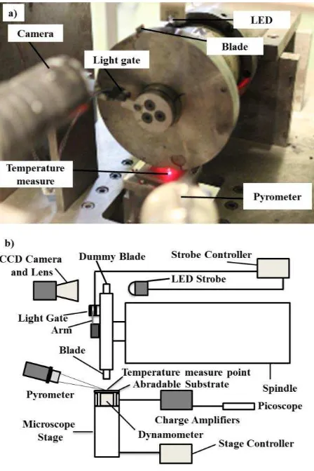
within a rotating metal disc, which is attached to the spindle using a HSK-C40 tool coupling. The rotating disc contains both a removable blade sample that is used to incur the abradable material, along with a dummy blade in a position 180 degrees opposed to the test blade for balancing. Abradable samples are then mounted below the rotating disc on top of a Z-axis microscope stage, which is then used to create incursion events between the blade and abradable samples, at rates ranging from 0.1 2000 µms-1 at intervals of 0.1 µms-1. The incursion conditions for a given test are set with a programmable stage controller prior to the test commencing.
[image:4.595.185.409.291.627.2]During a given test, stroboscopic imaging is used to characterise the blade tip at the top dead centre position [13,15]. This technique is used to measure the change in length of the blade during the incursion event. As shown in Figure 1b, an arm is mounted onto the disc and interrupts a light gate each time the disc rotates. This signal is used to trigger a high energy-short duration LED flash as the blade passes top dead centre. In this way, images of the moving blade can be captured using the CMOS camera, with minimal motion blur.
Figure 1 Test rig: a) Image view; b) Schematic block diagram
The contact force between the blade and abradable coating during the incursion has been measured using a piezo-electric dynamometer, located below the abradable sample (Figure 1b). The
Figure 1a, during each test the coating temperature is measured at a single point on the abradable surface, and is used to monitor the temperature of the coating throughout the test.
The incursion rate during a given test is controlled using Labview (National Instruments, Labview 2009), which is also used to capture the blade images from the camera, as well as the force and temperature measurements during the test. In this way changes in blade length indicative of wear or adhesive transfer along with corresponding contact forces and coating temperature, can be
determined at any point in the programmed incursion.
Additionally, material sectioning was also performed on the test specimens. This is undertaken on un-used samples to characterise differences with respect to structural composition, as well as on abraded specimens where the material response to the incursion is investigated. In the latter case, sections are taken in both the longitudinal and transverse directions with respect to the rub surface [15]. Microscope samples were vacuum impregnated with low viscosity epoxy resin before grinding and polishing.
2.2 Test Samples and Preparation
An abradable material consisting of an aluminium-silicon metal matrix, and a hexagonal boron nitride dislocator (AlSi-hBN) was thermally sprayed onto a flat steel plate to a nominal thickness of 3mm. In this material the metal matrix provides erosion resistance while the hBN allows the material to wear easily on contact with the blade. The coating was sprayed at two different values of
hardness, representative of typical values used in aero-engine compressors. The difference in hardness between the two sample sets was achieved by modifying the thermal spraying parameters, as detailed in the subsequent section.
A given sample was then mounted onto the microscope stage, and incurred against a flat titanium blade, at a pre-determined set of incursion conditions. The titanium blades were manufactured to a thickness of 2mm from Ti-6Al-4V, and had a nominal length of 25mm. Prior to testing the length and weight of each blade was recorded.
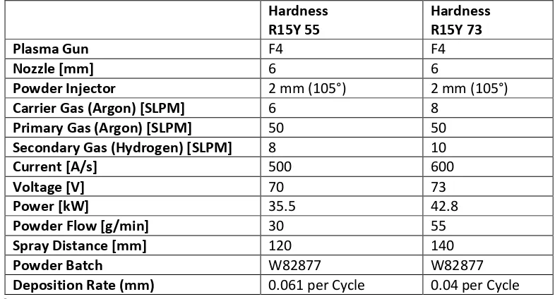
2.2.1 Material Hardness and Thermal Spray Parameters
Hardness R15Y 55Hardness R15Y 73
Plasma Gun F4 F4
Nozzle [mm] 6 6
Powder Injector 2 mm (105°) 2 mm (105°)
Carrier Gas (Argon) [SLPM] 6 8
Primary Gas (Argon) [SLPM] 50 50
Secondary Gas (Hydrogen) [SLPM] 8 10
Current [A/s] 500 600
Voltage [V] 70 73
Power [kW] 35.5 42.8
Powder Flow [g/min] 30 55
Spray Distance [mm] 120 140
Powder Batch W82877 W82877
[image:5.595.100.493.526.738.2]Deposition Rate (mm) 0.061 per Cycle 0.04 per Cycle
Typically, AlSi-hBN abradable materials used in aero-engine compressors are manufactured to hardnesses in the range of 45 to 75, measured on the Rockwell R15Y hardness scale [11]. In this study, the thermal spray parameters were modified to produce samples close to the upper and lower limits of typical usage, R15Y 55 and 73 respectively. Spraying was performed using a Sulzer Metco F4 9MC system [11, 16], with Argon and Hydrogen used as the primary and secondary gas flows respectively.
For a given powder feedstock, the properties of the coating produced in a plasma spraying process are primarily dependent on the deposition rate [11, 16], which in turn is a function of powder flow rate, the current input and associated ionisation temperature, spray distance, and the primary gas flow [6, 7]. As shown in Table 1, these parameters were modified to achieve deposition rates capable of producing coatings at the required hardnesses for this study.
2.2.2 Material Characterisation
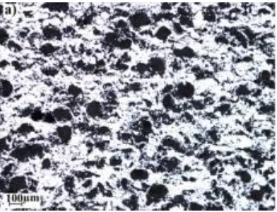
[image:6.595.200.396.348.498.2]The hardness of the two sample sets was measured using a Rockwell R15Y hardness indenter, and were found to be 55 ± 2.5 and 73 ± 2.2 respectively. Figure 2 shows microscope images of the softer coating in the as sprayed state. The Aluminium-Silicon phase is white, the hexagonal boron nitride dark grey, and the porosity black.
Figure 2 Microstructure of AlSi-hBN: a) Hardness R15Y 55; b) Hardness R15Y 73
The distinction between porosity and hexagonal boron nitride in Figure 2 is not clear. Therefore, in order to investigate how the fractions of the constituent phases have changed with hardness, the microscope images of the coatings were investigated using image segmentation [17, 18, 19]. In addition to the light field images shown above, images were taken using cross-polarized light [20]. As the hBN is crystalline it rotates the plane of polarisation and is clearly visible [19], this is shown in Figure 3. A binary threshold was then applied to the light field and cross-polarised images to map the Aluminium-Silicon and hBN phases respectively. Threshold values were automatically generated to minimise inter class variance [21], with the mean effectiveness metric 0.91±0.0066 for the light field images and 0.85±0.025 for the cross polarised images respectively. The remaining area after
Figure 3 Microstructure of AlSi-hBN at a hardness of R15Y 55 under: a) Normal Light; b) Cross Polarized Light.
Figure 4 shows the completed analysis for the R15Y 55 hardness sample. Using these images, the volume fractions of the different constituent phases were analysed using IMAGE J [22] and MATLAB. The influence of the metallographic preparation of the samples with respect to over estimating porosity due to opening cracks in the metal phase was also investigated. Images were opened, which in turn identified globular porosity and allowed an adjustment to be made with respect to the fractions of porosity and Al-Si respectively [23]. However, in this case, the influence of the preparation was found to be negligible.
Figure 4 Microstructural image analysis of the R15Y 55 hardness sample: a) Original microscope image; b) Image obtained using cross polarized light c) Map of phases d) Map of phases for the R15Y 73 hardness sample
Al-Si lower. In the following investigation, the effect of both this hardness change, along with the differences in the constituent phases, will be investigated in terms of abradability performance.
R15Y 55 R15Y 73
Metal Matrix [%] 57 ± 1.5 65 ± 0.58
Porosity [%] 19 ± 0.93 16 ± 0.56
hBN Particles [%] 24 ± 1.4 19 ± 0.42
Table 2 Mean volume fractions and standard error (n=6) of the phases in the AlSi-hBN coatings investigated (metal P>0.001, porosity P<0.05, hBN P<0.01)
2.2.3 Test Parameters
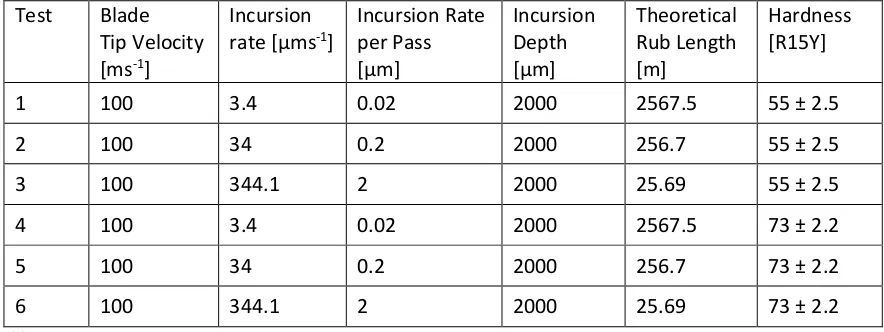
Tests were performed at a blade tip speed of 100ms-1 and incursion rates of 3.4, 34, and 344µms-1. These test parameters were selected as they had been previously identified as generating similar wear mechanisms to those observed in aero-engines. A single blade tip speed was chosen, as incursion rate had also been previously highlighted as the dominant parameter with respect to the wear mechanism [13, 14, 15]. In all of the tests, the incursion depth was constant at 2 mm, and was limited by the thickness of the coating samples. Based on the incursion rate and depth, the incursion rate per pass along with the total length of the rub can be calculated for the different tests
performed (Table 3). With respect to the theoretical rub length, L(t), it should be noted that this is a combination of the incursion rate (m/s), incursion depth (mm), and the blade tip radius [13, 15].
Test Blade Tip Velocity [ms-1]
Incursion rate [µms-1]
Incursion Rate per Pass [µm] Incursion Depth [µm] Theoretical Rub Length [m] Hardness [R15Y]
1 100 3.4 0.02 2000 2567.5 55 ± 2.5
2 100 34 0.2 2000 256.7 55 ± 2.5
3 100 344.1 2 2000 25.69 55 ± 2.5
4 100 3.4 0.02 2000 2567.5 73 ± 2.2
5 100 34 0.2 2000 256.7 73 ± 2.2
[image:8.595.76.518.366.532.2]6 100 344.1 2 2000 25.69 73 ± 2.2
Table 3 Test parameters
3. Results
3.1 Wear Mechanism
Test Incursion Rate per Pass [µm]
Hardness [R15Y]
Wear mechanism
1 0.02 55 ± 2.5 Blade wear / blade transfer on coating 2 0.2 55 ± 2.5 Initial Adhesion / Cutting Wear
3 2 55 ± 2.5 Cutting Wear
4 0.02 73 ± 2.2 Adhesive transfer to blade 5 0.2 73 ± 2.2 Initial Adhesion / Cutting Wear
6 2 73 ± 2.2 Cutting Wear
Table 4 Summary of the observed wear mechanisms
to be hardness dependent. In the case of the softer coating (R15Y 55) significant blade wear was evident, while for the harder coating (R15Y 73) adhesive transfer was observed from the abradable coating to the blade. Conversely, at the highest incursion rate tested, both coatings exhibited good cutting. The wear mechanisms presented above are in line with findings previously published by our group [13] and other researchers working on similar coatings [2,5].
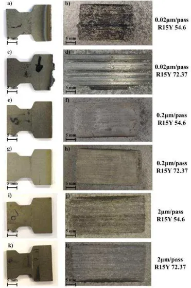
Figure 5 shows the blades and abradable sample at the end of the tests performed with the soft and hard coatings. The blade from test 1 (0.02µm pass-1 R15Y 55) shows significant thermal damage, with thermal dis-colouration of the titanium. Significant wear of the blade is also observed, with a dark grey transfer film on the surface of the abradable. It should also be noted that as a consequence of the reduced blade length, the rub length is lower than the predicted value, with a reduced arc of contact visible on the sample.
Conversely the blade from test 4 (0.02µm pass-1 R15Y 73), adhesive transfer from the abradable coating to the blade has occurred. However, there is also a point of thermal damage close to the edge of the blade sample. The corresponding abradable surface is also grooved due to the transfer, with the high point on the coating corresponding to the area of thermal damage and wear on the blade. A dark grey transfer film also appears present in this area. The blades and abradable samples post-test at the intermediate (0.2µm pass-1) and high (2µm pass-1) incursion rates for both
hardnesses show similar behaviour, with minimal blade wear and well cut surfaces on the abradable material.
Based on the observations presented it appears hardness of the abradable samples has a significant influence on the wear mechanisms occurring during the incursion. In the following sections the adhesive transfer and blade wear found at low incursion rates will be investigated.
3.2 Material transfer
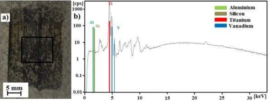
[image:10.595.75.517.565.734.2]An energy dispersive X-ray fluorescence (EDXRF) spectrometer (Fischerscope X-RAY XAN 250, Fischer Instrumentation, Lymington, UK) has been used to analyse the blade and abradable samples in terms of the photon count per second at a given energy level, and the elements these correspond too. Figure 6 shows a spectrum recorded for the soft abradable at low incursion rate (0.02µm pass-1 R15Y 55) where titanium transfer was observed, and was performed at 50 kV using a nickel primary filter with an anode current of 1000A to obtain the measurement. As shown in the figure, titanium and vanadium (comprising of two peaks as a result of both K and K emissions) were identified as present on the surface of the abradable sample, and have been transferred from the blade. A similar measurement was also performed on the low incursion rate test with the hard abradable (0.02µm pass-1, R15Y 73) at the edge of the rub track. This location corresponds to an area of thermal damage on the blade, and was also identified as titanium transfer.
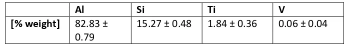
The adhesive transfer to the blade observed in Test 4 was also investigated using EDXRF in this case at 10 kV with no filter and an anode current of 1000A (Figure 7). As shown in the Figure, aluminium and silicon found in the coating are evident in the adhered material, along with titanium and
[image:11.595.73.523.204.355.2]vanadium present in the blade. This suggests the adhered material is a mixture of both the blade and coating. However, as the photon count in relatively low as consequence of the low atomic numbers of the elements, and a small amount of aluminium is also present in the titanium 6-4 used to manufacture the blades, it is difficult to determine the relative fractions of blade and coating material present, and the sample was further investigated using SEM combined with EDX analysis.
[image:11.595.123.471.491.536.2]Figure 7 EDXRF analysis of blade tip from Test 4: a) Analysis area; b) Spectrum
Table 5 Weight composition of adhered material observed on the blade in Test 4 shows the results of the EDX analysis, where a series of ten measurements have been recorded using a 30 µm
diameter sample area, and an average performed. As shown in the table, the Aluminium and Silicon phases represent a large proportion of the measurement indicating that the adhered material is primarily due to pick up from the coating, with only a small amount of blade material present highlighted by the relative weight fraction of titanium present.
Al Si Ti V
[% weight] 82.83 ± 0.79
15.27 ± 0.48 1.84 ± 0.36 0.06 ± 0.04
Table 5 Weight composition of adhered material observed on the blade in Test 4
3.3 Stroboscopic imaging, force & temperature Measurement
Figure 8 Blade Length Change Expressed in Terms of Rub Length, at Incursion rate of: a) 0.02µm·pass-1 R15Y 55; b) 0.2µm·pass-1 R15Y 55; c) 2µm·pass-1 R15Y 55; d) 0.02µm·pass-1 R15Y 73; e) 0.2µm·pass-1 R15Y 73; f) 2µm·pass-1 R15Y 73
Figure 8 a, b and c, show the maximum blade length change expressed in terms of rub length for the soft coating, and Figure 8 d, e and f the corresponding results for the hard coating. As shown in Figure 8 a, at an incursion rate of 0.02µm·pass-1 the blade shows initial adhesive behaviour before being continually worn by the soft coating. Conversely, as shown in Figure 8 d at the same incursion conditions but with a harder abradable, adhesion occurs. Similar results are also observed at an incursion rate of 0.2µm·pass-1, when comparing the soft (Figure 8 b) and hard (Figure 8 e) abradable coatings, however the magnitude of wear and adhesive events are now reduced. Finally, at an incursion rate of 2µm·pass-1, minimal changes in blade length are observed corresponding to good cutting for both hardnesses of coating.
Table 6 shows a summary of the force and temperature measurements obtained during the different tests. As the aim of this investigation is to consider global differences in abradability behaviour in response to changes in material hardness, average normal and tangential cutting forces along with average and maximum temperature are presented.
Incursion Rate per Pass [µm] Hardness [R15Y] Average Normal Force [N] Max Normal Force [N] Average Tangential Force [N] Max Tangential Force [N] Force Ratio Average Temperature [°C] Max Temperature [°C]
0.02 55 1485.1 2497.5 219.4 375.3 0.148 410.8 520.9
0.2 55 1150.3 1500.8 293.6 383.1 0.252 301.7 414.5
2 55 1410.1 2488.3 487.8 846.1 0.346 222.5 358
0.02 73 834.5 1243.6 75.6 200.7 0.111 372.6 496.0
0.2 73 1561.7 2401.3 538.9 1037.6 0.389 292.7 435.7
[image:12.595.77.510.71.333.2]2 73 2744.2 5624.5 1303.4 2713.8 0.493 224.3. 294.1
[image:12.595.74.534.593.722.2]As shown in Table 6, differences in force and temperature were observed for the two abradables investigated. In particular, these differences were more pronounced at the lowest incursion condition. In the case of the soft abradable, both normal and tangential forces were higher, along with average temperature. As the incursion rate is increased and cutting starts to occur, normal and tangential forces along with force ratio are lower for the soft abradable compared to the hard case, suggesting an increased ability to dislocate due to the higher hBN content. At both the intermediate and high incursion rates, temperatures remain similar or slightly higher for the soft abradable.
3.5 Material Sectioning
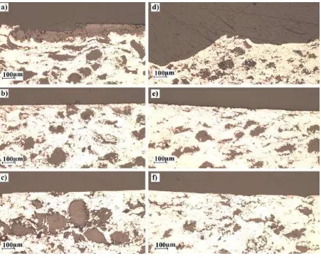
[image:13.595.74.525.261.624.2]Previous research has linked the cutting force to material behaviour, and more specifically consolidation of the abradable [15]. Figure 9 shows the sections of the softer (Figure 9 a, b, c) and the harder (Figure 9 d, e, f) coating.
Figure 9 Material response of the AlSi-hBN at an incursion rate of: a) 0.02 µm·pass-1 R15Y 55; b) 0.2 µm·pass-1 R15Y 55; c) 2 µm·pass-1 R15Y 55; d) 0.02 µm·pass-1 R15Y 73; e) 0.2 µm·pass-1 R15Y 73; f) 2 µm·pass-1 R15Y 55.
To investigate the compaction further ten images were taken from each section as well as ten from an as sprayed coating. A threshold was taken at an automatically chosen level, as described above, to give a map of the metal phase, this was then split into strips so the compaction could be
quantified at different depths below the rub surface. The results, summarised in Figure 10, were
ANOVA B S
[image:14.595.117.396.207.404.2](p<0.01) compaction was observed in the softer coating at both 0.02 and to a lesser extent at 0.2µm/pass to a depth of 590µm. No significant compaction was seen in the softer coating at 2µm/pass or for the harder coating at any of the incursion conditions tested.
Figure 10 Summary of compaction analysis for R15Y 55 coatings
As previously discussed, adhesive transfer was not uniform along the blade tip and areas of thermal damage were also observed (Figure 11). A section of the abradable sample was taken coinciding with the area of thermal damage on the blade and the associated titanium transfer to the abradable (Figure 11b).
Figure 11 T R Y -1 and a blade speed
100m s-1: a) Coating and blade; b) Microstructure with titanium layer identified.
65 200 330 460 590 720
0.0 0.2 0.4 0.6 0.8
µm below rub surface
M
e
ta
l
fr
a
c
ti
o
n
o
f
im
a
g
e
Control
2 µm/pass
0.2
0.02
[image:14.595.128.467.505.699.2]As shown in Figure 11, it is interesting to note that a high concentration of hBN exists in the sub-surface of the abradable sample in this region, and suggests that the local composition of the abradable sample may influence the wear mechanics observed for a given portion of the blade tip.
3.6 Overall Abradability
In the previous section, the response of two different abradables has been investigated at a range of incursion rates. As discussed, significant differences with respect to cutting behaviour have been highlighted at the low incursion rate condition. In the case of the soft abradable, wear of the blade occurred, with corresponding high forces and temperatures, coupled with titanium transfer and compaction of the abradable. Conversely for the hard abradable, force and temperature were reduced, with adhesion of abradable material to the blade tip, coupled with some consolidation of the coating. In the following section, the thermal behaviour of the two abradables will be further explored to investigate the differing response of the two materials.
4. Thermal Properties of the Coatings
As discussed, in order to change the hardness of the abradable sample, the constituent fractions of aluminium-silicon, hBN and porosity are varied. The effect of these changes has been investigated both in terms of the overall thermal diffusivity and conductivity through experimental investigation, as well as on a more local level via a finite element model.
4.1 Thermal Conductivity
[image:15.595.153.447.515.713.2]Freestanding samples of the abradable materials (10 x 10 x 2mm) were prepared for thermal analysis. The thermal properties of the samples were measured using a laser flash based approach [24], and was performed by LINSEIS (LINSEIS Messgeräte GmbH, Vielitzerstraße 43, D-95100 Selb, Germany). The apparatus measured specific heat capacity, density and thermal conductivity of the samples over the temperature range 30 °C to 500 °C, at 100 °C intervals. Figure 12 shows the experimental result of the thermal conductivity measurement for both abradable samples with respect to temperature.
Additionally, Table 7 shows the average thermal properties of the two abradables. As shown by these two results, the thermal properties of the softer abradable are significantly worse, with the softer abradable likely to retain more heat as a consequence of an incursion event. This result goes some way to explaining the increased wear seen for the softer abradable sample, as heat will remain close to the surface for longer than with the harder material.
Coating Thermal Diffusivity [cm2 s-1]
Heat capacity [J (g K)-1]
Density [g cm-3]
Thermal Conductivity [W (m K)-1]
Hard 0.104 1.174 1.77 21.79
[image:16.595.90.503.159.233.2]Soft 0.069 1.198 1.67 14.12
Table 7 Average thermal proprieties of the abradable coating for the temperature range 30°C to 500°C
4.2. Thermal model
In order to further investigate the change in properties between the different hardnesses of abradable an image based finite element model has been created. The image processing described above was used to create a map of phases in the micro structure as shown in Figure 4c. This map was converted into a finite element model such that one pixel in the original images became one element in the model as described by Bolot et al. [25]. The elements were then given the relevant material properties as shown in Table 8. Elements of hBN were randomly split into 36 sets and assigned orientations from 0 to 175 degrees.
For both
hardness’s
six models were created from different image pairs, with each model
having an area of 1000
pixels (e.g.
579µm square). Inter splat boundaries in the metal phase
have not been modelled due to difficulties determining material properties, and observing
such fine elements of the microstructure while still sampling a large enough area to be
representative. This approach is consistent with previous work in the field [25, 26].
Phase Thermal conductivity [W (m K)-1]
Specific heat capacity
(Cp) [J (g K)-1] Density [kg m -3]
Metal (AlSi 12%) 165 [27] 0.910 2.7
hBN 200, 30 [28] 1.425 2.1
Porosity (air) 0.0257 1.005 1.205×10⁻³
Table 8 Material properties used in the finite element models.
[image:16.595.65.533.479.582.2]Figure 13 Average Thermal diffusivity from the models with standard error and measured thermal diffusivity at 30°C n=6 (model model p<0.05)
As shown by Figure 13, the model can only account for around 85% of the change from the bulk value of AlSi used, as the inter splat boundaries have not been modelled, with this result comparing favourably with other, similar models [29]. The trend in the results is consistent between the
experimental and modelled values, and indicates that the effects that are responsible for the change in behaviour investigated have been modelled successfully.
Temperature results from the models, such as that shown in Figure 14, show areas with very high temperature gradients indicating barriers to heat flow at the boundary between the hBN and the metal phase (as indicated in Figure 14). This is due to thin pores that separate the hBN from the metal. As the harder abradable contains less hBN this explains the moderate change in porosity between the two of coating and causes the change in diffusivity and heat flow as
observed in Figure 14. Additionally, as previously discussed the softer abradable is particularly prone to increased consolidation at low incursion conditions, and exhibits higher normal forces as a
consequence. This increased energy input, when combined with poor thermal diffusivity leads to contact temperatures sufficient to soften the titanium blade. This evidenced through both the identified deposition of blade material on the abradable, as well as the low tangential cutting forces, indicative of a lubricious surface layer. Conversely, for the high hardness samples, temperatures are reduced and material transfers from the lower melting point abradable to the blade. As incursion rate increases, cutting performance of the soft abradable becomes superior with associated lower forces, with the reduced thermal diffusivity of more limited significance.
The temperature results from the models
heterogeneous thermal properties on the surface temperature. Some areas of the surface are able to dissipate heat quickly, however where hBN is close to the surface the heat is trapped by the porosity described above leading to hot spots on the surface (as indicated in Figure 14). Going back to the result for the higher hardness abradable at low incursion rate, this goes some way to
explaining the mixture of adhesion and wear observed across the blade profile, where the area of thermal damage on the blade corresponds to a local increase in hBN concentration. This variation is a consequence of the nature of the thermal spraying process, and whilst a nominal hardness and
0 0.05 0.1 0.15 0.2 0.25 73 55
T
h
er
m
al
Dif
u
sivi
ty
(c
m
2/s)
Coating Hardness (HR15Y)
thermal diffusivity is reached for a given sample, localised wear events may still occur as a
[image:18.595.80.519.143.323.2]consequence of the distribution of the constituent phases present. This is highlighted in Figure 11, showing that, even on hard coatings, a locally high concentration of hBN can lead to thermally driven wear, where adhesion was otherwise present.
Figure 14 Showing the map of phases, temperature and heat flux results for a model of a 55 (A) and a 73 (B) hardness abradable.
5. Discussion
The study has shown that at low incursion rates, significantly different wear mechanisms exist for the two hardnesses. The harder coating produced adhesive transfer from the abradable specimen to the blade whereas low hardness samples showed evidence of compaction of the abradable and extensive wear of the blade. At intermediate and high incursion rates, good cutting was generally observed at both hardnesses with some compaction present in the softer abradable at the intermediate incursion rate.
The mechanisms summarised above are in line with those observed in other studies of the same or similar rubs [2,5,13-15,20]. However, where previous studies have found either blade wear or adhesive transfer at low incursion rates depending on the abradable used, in this work both
mechanisms have been produced on abradables from the same powder. This step adds a dimension to the wear maps previously produced and highlights the importance of the highly variable
abradable properties in both wear testing and service.
The reason for the changes in wear mechanism produced by coatings of different hardnesses has also been investigated. Significant differences in the coating microstructure have been observed and previously linked to spray parameters and erosion resistance [11]. In this study the thermal
properties of the coating have been linked to these microstructure changes through diffusivity measurements and microstructure modelling of the coatings. These techniques have shown the main barriers to heat flow in the coatings to be the hBN AlSi boundary. Modelling the coatings has
hot spots near the rubbing surface in areas with a high concentration of hBN near the surface.
Thus the change in wear behaviour with microstructure as well as variations in wear mechanism across the width of single test samples has been explained. The blade wear observed for the soft abradable is attributable to poor heat dissipation from the blade contact, and is a consequence of
poor conductivity at the boundaries between the hBN and the AlSi phase. Local blade wear events observed for the high hardness sample, may also be a consequence of local hBN concentrations inherent to the structure of the thermally sprayed abradable material.
The possibility for the thermal diffusivity of the abradable to drive the wear mechanism of the rub has previously been suggested [30] however difficulties in modelling the contact and confounding of thermal and other properties have made it impossible to predict weather this actually happens. It is the main finding of this study that, at low incursion rates, the wear mechanism is dictated by the thermal properties of the abradable and that the range of properties needed to produce either adhesion or severe blade wear is contained within the most commonly used specifications of these materials. Thus in service engines should expect to encounter both mechanisms depending on the spray parameters used.
Further work modelling these coatings should aim to determine the influence of cracks and pores in the metal phase of these coatings as it is clear that without taking these into account the coatings cannot be modelled perfectly.
6. Conclusions
The purpose of this study was to investigate the effect of abradable hardness on the wear mechanisms produced by a tip-shroud rub. To this end a series of tests have been performed on abradable samples of two different hardnesses, over a range of incursion conditions. These tests have shown the hardness of the abradable dictates the wear mechanism at low incursion rates.
This effect has been linked to the relatively poor thermal diffusivity of low hardness abradables. The thermal properties of the abradables have further been shown to be dependent on the
microstructure produced during the thermal spraying process with the boundary between hBN and AlSi phases creating a barrier to heat flow.
Some evidence has also been found to suggest that variation in wear mechanism across the width of the blade is due to areas of high hBN concentration. These areas could adversely affect the local thermal properties of harder coatings producing hot spots on the surface of the abradable causing the blade to soften and wear.
References
[1] Sporer D., Wilson S., Giovanetti I., Refke A., Giannozzi M. On the potential of metal and ceramic based abradables in turbine seal application. Proceedings of the Thirty-Sixth Turbomachinery
Symposium 2007, Texas A&M University, pp. 79-86.
[2] Bounazef M., Guessasma S., Ait Saadi B. The wear, deterioration and transformation phenomena of abradable coating BN-SiAl-bounding organic element, caused by the friction between the blades and the turbine casing. Materials Letters 2004; 58: 3375-3380.
[4] Wilson S. Thermally sprayed abradable coating technology for sealing in gas turbines. Future of
gas turbine technology 6th International Conference,Brussels, Belgium, October 17-18 2012, Paper
ID number 51.
[5] Borel M.O., Nicoll A.R., Schlapfer H.W., Schmid R.K., The wear mechanisms occurring in abradable seals of gas turbines, Surface and Coatings Technology 1989; 39/40: 117-126.
[6] Pawlowski L. The science and engineering of Thermal Spray Coatings.2nd ed., John Wiley & Sons Ltd., 2008. ISBN 978-0-471-490494.
[7] Rhys-Jones T.N. Thermally sprayed coating systems for surface protection and clearance control applications in aero engines. Surface and Coating Technology 1990; 43/44: 402-415.
[8] Vardelle M., Fauchais P., Plasma spray process: diagnostics and control?, Pure Appl. Chem. 1999, 71, No.10: 1909-1918.
[9] Dorfman M.R., Fiala P., Hajmrle K., Wilson S. Future abradable requirements needed by
aerospace OEM`s and their material and equipment suppliers. Proceedings of GT2007, ASME Turbo
Expo 2007: Power for Land, Sea and Air, Montreal, Canada, May 14-17 2007.
[10] Lugscheider E., Zwick J., Hertter M., Sporer D. Control of Coating Properties of Abradable Seals by On-line Process Diagnostics. ITSC 2005, Conference & Exposition, Thermal Spray Potential, Basel, Switzerland, May 2-4 2005.
[11] Sulzer Metco, Solutions Flash, Cause and Effect of Metco 320NS Spray Parameters for
Optimisation of Coating Hardness and Service Life,
http://www.oerlikon.com/metco/en/products-services/coating-materials/thermal-spray/abradables-polymer-fillers/
(Last accessed 8 June2015).
[12] Yi M., Huang B., He J. Erosion wear behaviour and model of abradable seal coating. Wear 2002; 252: 9-15.
[13] Fois N., Stringer J., Marshall M.B., Adhesive transfer in aero-engine abradable linings contact. Wear 2013; 304: 202-210.
[14] Stringer J., Marshall M.B. High speed wear testing of an abradable coating. Wear 2012; 294-295: 257-263.
[15] Fois N., Watson M., Stringer J., Marshall M.B. An investigation of the relationship between wear and contact force for abradable materials, Proceeding of Institution of Mechanical Engineers, Part J:
Journal of Engineering Tribology, July 23, 2014, DOI:10.1177/1350650114545139.
[16] Sulzer Metco, Oerlikon Metco, Material Product Data Sheet, Aluminum Silicon Hexagonal Boron Nitride, Thermal Spray Powder Products: Metco 320NS,
[17] Sporer D., Wilson S. Current and Next-Generation Titanium Blade Compatible Compressor Abradable Coatings, Thermal Spray 2012: Proceedings from the International Thermal Spray
Conference and Exposition, Houston, Texas, USA, May 21-24, 2012, Houston.
[18] Faraoun H.I., Seichepine J.L., Coddet C., Aourag H., Zwick J., Hopkins N., Sporer D., Hertter M. Modelling route for abradable coatings. Surface and Coating Technology 2006; 200: 6578 6582.
[19] Faraoun H.I., Grosdidier T., Seichepine J.L., Goran D., Aourag H., Coddet C., Zwick J., Hopkins N. Improvement of thermally sprayed abradable coating by microstructure control. Surface and Coating
Technology 2006; 201: 2303-2312.
[20] Sulzer Metco, Identification of Hexagonal Boron Nitride in Amdry 958 Coatings Using Polarized Light Microscopy (PLM), Sulzer Metco Canada, May 2010.
[21] Otsu N. A threshold selection method from Gray-Level Histograms. IEEE transactions on sytems,
man, and Cybernetics 1979; 1: 62 66.
[22] Rasband W., National Institute of Health, USA.
http://rsbweb.nih.gov/ij/
. (Last accessed 14 September 2014).[23] Matejicek J., Kolman B., Dubsky J., Neufuss K., Hopkins N., Zwick J. Alternative methods for determination of composition and porosity in abradable materials. Materials Characterization 2006; 57: 17-29.
[24] Parker W.J., Jenkins R.J., Butler C.P., Abbott G.L. Flash Method of determining thermal diffusivity, heat capacity and thermal conductivity. Journal of Applied Physics 1961; 32.
[25] Bolot R., Seichepine J.L., Qiao J.H., Coddet C. Predicting the Thermal Conductivity of AlSi/Polyester Abradable Coatings: Effects of the Numerical Method. Journal of Thermal Spray
Technology 2011; 20: 39-47.
[26] Huang M., Li Y. X-ray tomography image-based reconstruction of microstructural finite element mesh models for heterogeneous materials. Computational Materials Science 2013; 67: 63 72. DOI:10.1016/j.commatsci.2012.08.032
[27] Zhang Y., Wang X., & Wu J. The influence of silicon content on the thermal conductivity of Al-Si/diamond composites. International Conference on Electronic Packaging Technology & High
Density Packaging 2009; 708 712. doi:10.1109/ICEPT.2009.5270658.
[28] Sichel E.K., Miller R.E., Abrahams M.S., and Buiocchi C.J. Heat capacity and thermal conductivity of hexagonal pyrolytic boron nitride. Physical review B 1976; 13, 4607 Published 15 May 1976. DOI: http://dx.doi.org/10.1103/PhysRevB.13.4607.
![Figure 4 shows the completed analysis for the R15Y 55 hardness sample. Using these images, the volume fractions of the different constituent phases were analysed using IMAGE J [22] and MATLAB](https://thumb-us.123doks.com/thumbv2/123dok_us/7748618.166891/7.595.122.476.356.626/figure-completed-analysis-hardness-fractions-different-constituent-analysed.webp)