ePrints Soton
Copyright © and Moral Rights for this thesis are retained by the author and/or other
copyright owners. A copy can be downloaded for personal non-commercial
research or study, without prior permission or charge. This thesis cannot be
reproduced or quoted extensively from without first obtaining permission in writing
from the copyright holder/s. The content must not be changed in any way or sold
commercially in any format or medium without the formal permission of the
copyright holders.
When referring to this work, full bibliographic details including the author, title,
awarding institution and date of the thesis must be given e.g.
UNIVERSITY OF SOUTHAMPTON
FACULTY OF ENGINEERING, SCIENCE & MATHERMATICS School of Engineering Sciences
CHARACTERISATION AND COMPUTATIONAL
MODELLING OF ACRYLIC BONE CEMENT
POLYMERISATION
Adam Briscoe
A thesis submitted in partial fulfilment of the requirements for the degree of
Doctor of Philosophy
School of Engineering Sciences
Bioengineering Sciences Research Group
Abstract
Bioengineering Sciences Research Group School of Engineering Sciences
University of Southampton
Doctor of Philosophy
by Adam Briscoe
Total joint replacement is one of the most successful surgical procedures and is a proven treatment for arthritis. Despite low failure rates, the wide application of the treatment means that large numbers of prostheses fail and must be revised. Improved pre-clinical testing methods for these orthopaedic devices may assist in developing new prostheses with improved clinical results. Computational modelling of biological systems is becoming increasingly accurate and is a much quicker and cheaper alternative to physical testing, but continued development is necessary to ensure computational models produce accurate and reliable predictions of implant behaviour.
Acrylic bone cements have been used as a method of fixation for over 50 years but despite improvements in cement handling techniques and numerous attempts to improve the mechanical properties of the cement in other ways, the cement is often highlighted as the weak link in the joint replacement system. Aseptic loosening is cited as the cause for the majority of revision operations and cement degradation has been shown to be a contributor to the loosening process. In-vivo, cement is subject to cyclic loads and these are the primary cause of cement damage. Residual stresses generated during the polymerisation of the cement are now thought to play a significant role in cement failure.
TABLE OF CONTENTS
1 INTRODUCTION 1
2 STATEMENT OF PROBLEM AND OBJECTIVES OF RESEARCH 6
3 LITERATURE REVIEW 9
3.1 JOINT REPLACEMENT 9
3.1.1 ANATOMY OF SYNOVIAL JOINT 9
3.1.2 JOINT DEGRADATION 11
3.1.3 DIFFERENT TYPES OF JOINT REPLACEMENT 12 3.1.4 CEMENTED JOINT REPLACEMENT PROCEDURE 17
3.2 BONE CEMENT 20
3.2.1 CEMENT INGREDIENTS 20
3.2.2 MIXING TECHNIQUES 21
3.2.3 CEMENT POLYMERISATION KINETICS 25
3.2.4 MECHANICAL PROPERTIES OF CURING CEMENT 27 3.2.5 VOLUMETRIC CHANGES IN CURING CEMENT 30
3.3 REASONS FOR JOINT REVISION 32
3.3.1 SURGICAL TRAUMA 32
3.3.2 ASEPTIC LOOSENING 32
3.4 FINITE ELEMENT MODELLING OF BONE CEMENT 46
3.4.1 FINITE ELEMENT MODELLING OF DAMAGE 47
3.4.2 CEMENT POLYMERISATION MODELLING 48
3.4.3 RESIDUAL STRESS PREDICTION 51
3.5 LITERATURE REVIEW SUMMARY 55
4 THERMAL MODELLING OF BONE CEMENT CURE 56
4.1 INTRODUCTION 56
4.2 POLYMERISATION MODEL 58
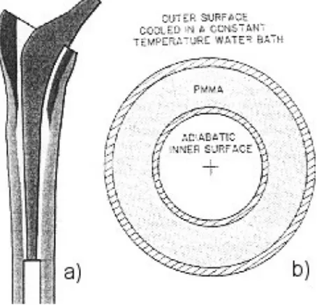
4.3 CONCENTRIC CYLINDERS MODEL 61
4.3.1 METHOD 61
4.3.2 RESULTS AND DISCUSSION 62
4.3.3 CONCLUSIONS 65
4.4 IDEALISED STEM MODEL 67
4.4.1 INTRODUCTION 67
4.4.2 METHOD 67
4.4.3 RESULTS AND DISCUSSION 70
4.5 COMPARISON OF IDEALISED STEM MODEL WITH EXPERIMENTAL RESULTS 101
4.5.1 INTRODUCTION 101
4.5.2 METHODS 101
4.5.3 RESULTS AND DISCUSSION 103
4.6 RESURFACING HIP ARTHROPLASTY MODEL 105
4.6.1 INTRODUCTION AND OBJECTIVES 105
4.6.2 METHODS 105
4.6.3 RESULTS AND DISCUSSION 108
4.7 TOTAL KNEE REPLACEMENT MODEL 111
4.7.1 INTRODUCTION 111
4.7.3 RESULTS AND DISCUSSION 113
4.8 THERMAL MODELLING SUMMARY 115
5 MEASUREMENT OF PMMA CURING PARAMETERS USING DIFFERENTIAL
SCANNING CALORIMETRY (DSC) 116
5.1 INTRODUCTION 116
5.2 MATERIALS AND METHODS 118
5.2.1 THEORY 118
5.2.2 EXPERIMENTAL TECHNIQUE 122
5.3 RESULTS 123
5.3.1 FITTED MODEL 126
5.4 DISCUSSION 129
5.5 DSC CURE PARAMETER MEASUREMENT SUMMARY 130
6 ULTRASONIC CURE MONITORING 131
6.1 INTRODUCTION 131
6.2 MATERIALS AND METHODS 133
6.2.1 EXPERIMENTAL PROCEDURE 134
6.2.2 ACOUSTIC THEORY AND DATA PROCESSING 135
6.2.3 DISPERSION ADJUSTMENT 139
6.2.4 MATERIAL PROPERTY CALCULATION 141
6.3 RESULTS 144
6.3.1 COMPRESSIVE WAVE RESULTS 146
6.3.2 SHEAR WAVE RESULTS 155
6.3.3 MODULI 161
6.4 DISCUSSION 170
6.5 ULTRASONIC CURE MONITORING SUMMARY 174
7 TENSILE CURE TESTS 175
7.1 MATERIALS AND METHODS 175
7.2 RESULTS 177
7.3 DISCUSSION 179
7.4 TENSILE CURE TEST SUMMARY 180
8 BONE CEMENT SHRINKAGE MODELLING 181
8.1 INTRODUCTION 181
8.2 METHOD 183
8.3 RESULTS 185
8.4 DISCUSSION 188
8.5 COMPARISON MODEL 189
8.5.1 INTRODUCTION 189
8.5.2 METHOD 189
8.5.3 RESULTS 190
8.5.4 DISCUSSION 192
8.6 SHRINKAGE MODELLING SUMMARY 193
10 FURTHER WORK 199
11 BIBLIOGRAPHY 201
APPENDIX I – MODEL DRAWINGS AND DIMENSIONS 209
APPENDIX II – FINITE ELEMENT MODELLING AND RESULTS PROCESSING
CODES 212
THERMAL MODEL OF IDEALISED STEM WITH 2MM CEMENT MANTLE 212
MECHANICAL ANALYSIS OF IDEALISED STEM WITH 2MM CEMENT MANTLE 223
USERSW ALTERED CODING (FOR SHRINKAGE OF POLYMERISING CEMENT) 231
MATLAB CODING FOR PROCESSING OF ULTRASONIC RESULTS 233
APPENDIX III – TABLES OF RESULTS FROM ULTRASONIC CALCULATIONS 235
APPENDIX IV - CONFERENCE ABSTRACTS AND JOURNAL PUBLICATIONS 240
APPENDIX V – LIST OF ACRONYMS 260
TABLE OF FIGURES
Figure 1-1 - Main features of a (a) normal hip and (b) osteoarthritic hip [105] ... 1
Figure 1-2 - Radiographs and photographs of Charnley (left) and Judet (right) prostheses. ... 2
Figure 1-3 - Percent of cemented total hip arthroplasties revised due to aseptic loosening. Different coloured lines represent implants inserted in a different 5 year period between 1979 and 1991 [72].... 5
Figure 3-1 - Structure of a typical synovial joint [76]... 9
Figure 3-2 - Structure of a typical long bone [76]... 10
Figure 3-3 – Normal joint (left) compared to an osteoarthritic (right) joint [76]... 11
Figure 3-4 - Diagram of; a) a normal knee joint and b) a knee joint suffering from osteoarthritis [76] ... 12
Figure 3-5 - X-ray of a Charnley hip replacement in-situ. ... 14
Figure 3-6 - Three designs of conventional cemented femoral hip stem (left-right: Charnley, C-stem from DePuy™ and Exeter from Stryker™ Howmedica)... 14
Figure 3-7 - A metal on metal hip resurfacing joint in its acetabular cup [22]... 15
Figure 3-8 - Generic joint showing the natural joint (left) and the make up of a cemented total joint replacement (right). ... 16
Figure 3-9 - Conventional knee implant (left) compared to uni-condylar knee implant (right) [22]... 17
Figure 3-10 - Prepared acetabulum and tibia with their respective joint replacement components (cement not shown) [129] ... 18
Figure 3-11 - Insertion of femoral hip (left) and femoral knee (right) components into the prepared femur (cement not shown) [22]... 19
Figure 3-12 - Diagrams of completed and closed hip and knee total arthroplasty [129]... 19
Figure 3-13 - Photograph of Cem-Vac™ cement mixing system. Syringe with funnel, sealing plunger, nozzle cutter, cement delivery gun, sachet of cement powder and vial of liquid monomer are shown... 23
Figure 3-14 – Typical procedure for vacuum mixing cement [21]. ... 24
Figure 3-15 - Argand diagram of rheological properties of cure over time showing that both the storage and loss modulus increase during polymerisation... 28
Figure 3-16 – Maxwell (left) and Voigt (right) elements. ... 29
Figure 3-17 - S-N curves for plain PMMA compared to PMMA with radiopacifier (Ro PMMA) and PMMA with both radiopacifier and antibiotics (Ro PMMA + Ant) (reproduced from [6]). ... 30
Figure 3-18 - Volume change as a function of time exhibited in (a) vacuum mixed and (b) hand mixed bone cement [83]. ... 31
Figure 3-19 - Radiograph indicating distal and proximal loosening of the femoral hip component [20]. ... 33
Figure 3-20 - Temperatures of cement and bone during polymerisation, reproduced from Starke et al. [110]. ... 36
Figure 3-21 - Damage accumulation of bonded and unbonded stem cement mantles [119]... 40
Figure 3-22 - Fracture surface showing large pore and smaller adjacent pores where cracks have initiated [48]. ... 42
Figure 3-23 - Pre-load cracking (shown as specks) in 5 in-vitro 2-dimensional models of femoral hip component replacement [58] ... 44
Figure 3-24 - Radial crack observed after polymerisation [91] ... 44
Figure 3-25 - Gap at the cement-bone interface observed after polymerisation [91]... 45
Figure 3-26 - Comparison of damage accumulation predicted including porosity, creep and residual stress [51]. ... 48
Figure 3-27 - Geometry used in finite element models of cement polymerisation adopted by (a) Starke et al. [110] and (b) Baliga et al. [7]. ... 49
Figure 3-28 - Geometry used in finite element models of cement polymerisation adopted by (a) Li et al. [62] and (b) Borzacchiello et al. reproduced from [12]... 50
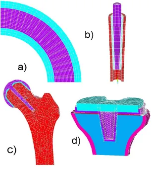
Figure 4-1 - Model geometries used in different chapters of the present work: a) Concentric cylinders, b) Idealised stem, c) Femoral head resurfacing, d)Tibial component of TKR ... 57
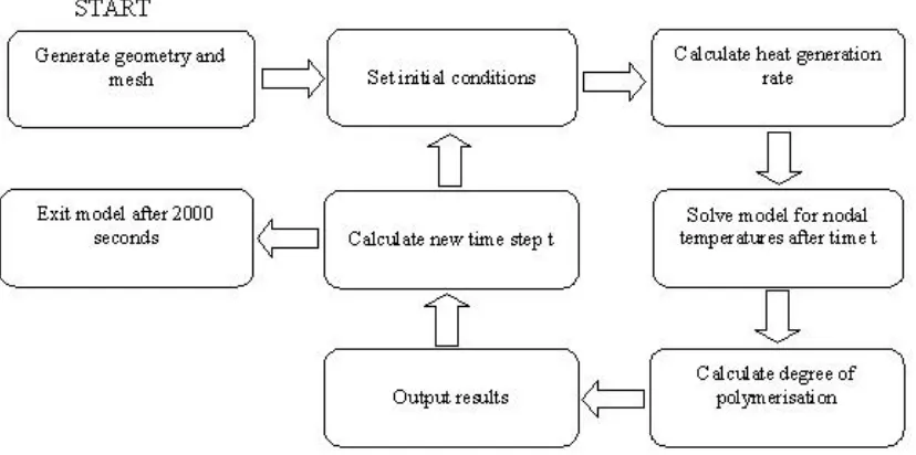
Figure 4-2 - Flow chart describing method of thermal computational modelling... 60
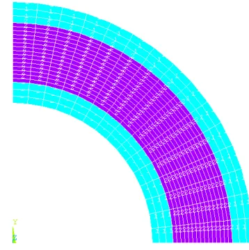
Figure 4-3 - Quadrilateral mesh of concentric cylinders model ... 62
Figure 4-4 - Temperature history across cement mantle in the radial direction. ... 63
Figure 4-5 - Polymerisation history across cement mantle in the radial direction. ... 63
Figure 4-7 -Temperature history of Baliga model with low total heat liberated (1.4x10⁸J/m3)... 65
Figure 4-8 - Hexahedral mesh of idealised hip stem model. ... 68
Figure 4-9 - Polymerisation curves for standard model... 71
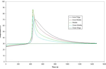
Figure 4-10 - Temperature profiles for standard model... 71
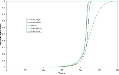
Figure 4-11 - Degree of polymerisation during cure of standard model at the time when the node at the radial and longitudinal centre of the mantle reaches a degree of polymerisation of 0.5. ... 72
Figure 4-12 - Polymerisation curves from a model with just the stem-cement interface modelled as debonded. ... 73
Figure 4-13 - Temperature curves from a model with just the stem cement interface modelled as debonded. ... 74
Figure 4-14 - Polymerisation curves for model with both stem-cement and cement-bone interfaces modelled as debonded. ... 74
Figure 4-15 - Temperature curves for model with both stem-cement and cement-bone interfaces modelled as debonded. ... 75
Figure 4-16 - Comparison of average degree of polymerisation curves from models with perfectly conductive (bonded) interfaces, stem-cement interface contact resistance and stem-cement & cement-bone interface contact resistances... 76
Figure 4-17 - Comparison of average temperatures from models with contact, stem-cement interface contact and stem-cement & cement-bone contact modelled... 76
Figure 4-18 - Location of nodes taken for mesh convergence results analysis... 77
Figure 4-19 – Results with one element through cement thickness... 78
Figure 4-20 - Results with two elements through cement thickness... 78
Figure 4-21 - Results with three elements through cement thickness. ... 79
Figure 4-22 - Results with five elements through cement thickness... 79
Figure 4-23 - Results with seven elements through cement thickness. ... 80
Figure 4-24 - Distal node temperature with different density of elements through thickness, summarising Figure 4-19 - Figure 4-23 for just the distal node enabling quick mesh convergence review. ... 81
Figure 4-25 - Change in temperature profiles during cure as a result of variation in activation energy. ... 82
Figure 4-26 - Change in degree of polymerisation during cure as a result of variation in activation energy. ... 83
Figure 4-27 - Change in temperature profiles during cure as a result of varying K0. ... 84
Figure 4-28 - Change in degree of polymerisation during cure as a result of varying K0... 85
Figure 4-29 - Change in temperature profiles during cure as a result of different m input... 86
Figure 4-30 - Change in degree of polymerisation during cure as a result of different m input. ... 86
Figure 4-31 - Change in temperature profiles during cure as a result of different n input. ... 87
Figure 4-32 - Change in degree of polymerisation during cure as a result of different n input... 87
Figure 4-33 - Change in temperature profiles during cure as a result of different Qtot input... 88
Figure 4-34 - Change in degree of polymerisation during cure as a result of different Qtot input. ... 89
Figure 4-35 - Temperatures during cure using different initial stem temperatures. ... 91
Figure 4-36 – Degree of polymerisation profiles for low, room and high temperature stem models taken at time when a node in the centre of the cement mantle is at 0.5 degree of polymerisation. ... 91
Figure 4-37 - Polymerisation profile for body temperature (37ºC) stem taken at a time when a node in the centre of the cement in the longitudinal and radial direction has reached a degree of polymerisation of 0.5. ... 92
Figure 4-38 - Geometry for model with 5mm cement mantle... 93
Figure 4-39 - Polymerisation curves for model with 5mm cement mantle and 2mm cement mantle. .... 94
Figure 4-40 - Degree of polymerisation for model with 5mm cement mantle taken at the time when a node in the centre of the cement in the longitudinal and radial direction has reached a degree of polymerisation of 0.5. ... 95
Figure 4-41 - Differences in temperatures at the interfaces during cure of a 5mm cement mantle. ... 96
Figure 4-42 - Temperature profiles for model with 5mm cement mantle and 2mm cement mantle. ... 96
Figure 4-43 - Idealised stem model with 1 degree of misalignment. ... 97
Figure 4-44 - Contour plot of the degree of polymerisation during cure of an idealised stem with 1 degree of misalignment taken at the time when a node in the centre of the cement in the longitudinal and radial direction has reached a degree of polymerisation of 0.5. ... 98
Figure 4-45 - Temperature along bone-cement interface on left side of misalignment model. ... 99
Figure 4-46 - Temperature along bone-cement interface on right side of misalignment model... 99
Figure 4-48 - Graph of temperatures produced from finite element simulation of experiment combined
with temperatures measured during experimental validation. ... 104
Figure 4-49 - Bone, cement and prosthesis geometry... 106
Figure 4-50 - Nodes from which results were calculated ... 107
Figure 4-51 - Temperature history in resurfaced femoral head with 2mm cement mantle. ... 108
Figure 4-52 - Temperature history in resurfaced femoral head with 4mm cement mantle. ... 109
Figure 4-53 - Necrosis index in resurfaced femoral head with 2mm cement mantle... 109
Figure 4-54 - Necrosis index in resurfaced femoral head with 4mm cement mantle... 110
Figure 4-55 - Two geometries used in the simulations; the first is a view of the posterior half of a 1mm cement layer, no stem cement and small tray (1_N_S), the second shows the anterior half of a 4mm cement layer with stem cement and a large tray (4_Y_L)... 112
Figure 4-56 - Necrosis index contour plots (1 or 4 refers to cement thickness in mm, Y or N refers to whether or not cement is used on the stem and L or S refers to the use of a large or small tibial tray). ... 114
Figure 5-1 - Heat liberation curve showing possible errors produced by late start on the DSC. ... 121
Figure 5-2 - Heat curves from DSC experiments after subtraction of sample pan and bone cement specific heat capacity baselines... 123
Figure 5-3 - Plot for the determination of the activation energy from Tf. ... 124
Figure 5-4 - Plot for the determination of the activation energy from Tp... 125
Figure 5-5 - Plot for the determination of the activation energy from T-f. ... 125
Figure 5-6 - Experimental and numerical curves using published variables for all different rates of temperature increase. Some experiments were run twice after the first set of results gave unexpected results others were only run this second time... 127
Figure 5-7 - Experimental and numerical curves using fitted variables for all different rates of temperature increase. ... 128
Figure 6-1 - Isometric views of the mould cavity and reflective top faces of the ultrasound experimental jig. ... 133
Figure 6-2 - Diagram showing path of recorded signals through polyethylene and PMMA... 136
Figure 6-3 - Ultrasonic wave impedances for both compressive and shear waves through polyethylene converted using a relationship of density to velocity for polyethylene [94] from experimental data for the impedance with frequency for a similar polymer with different density [128]. ... 141
Figure 6-4 - Thickness over time for both compressive and shear wave tests measured using a micrometer during exsperiments. ... 144
Figure 6-5 - Initial experimental data showing the recorded change in the ultrasonic signal during polymerisation. The vertical axis shows time from mixing of the cement, the horizontal axis shows propagation time for the signal, contour colours denote the amplitude of the signal with red denotinging a high peak and blue denoting a low trough... 145
Figure 6-6 - Raw signal taken at 720s from compressive wave experiment... 146
Figure 6-7 - Fourier spectra of both the first (A) and second (B) compressive wave echoes at the end of polymerisation... 147
Figure 6-8 - Reflection coefficient at the polyethylene PMMA interface at the end of polymerisation. ... 148
Figure 6-9 - Compressive wave impedance of PMMA at the end of polymerisation... 149
Figure 6-10 - Reflection coefficient at the PMMA/steel interface at the end of polymerisation... 149
Figure 6-11 - Compressive wave attenuation as a function of frequency at the end of polymerisation. ... 150
Figure 6-12 - Sonic velocity through bone cement at the end of polymerisation... 151
Figure 6-13 - Density of bone cement at the end of polymerisation. ... 152
Figure 6-14 - Compressive wave attenuation through bone cement over time during polymerisation.153 Figure 6-15 - Compressive wave velocity through bone cement during polymerisation. ... 153
Figure 6-16 - Density of bone cement during polymerisation measured using compressive wave. ... 154
Figure 6-17 - Raw signal taken at 900s into shear wave experiment. ... 155
Figure 6-18 - Shear wave reflection coefficient from the polyethylene/bone cement interface at the end of polymerisation. ... 156
Figure 6-19 - Shear wave impedance of bone cement at the end of polymerisation... 156
Figure 6-20 - Shear wave reflection coefficient from the bone cement/steel interface at the end of polymerisation... 157
Figure 6-21 - Shear wave attenuation through bone cement at the end of polymerisation... 157
Figure 6-22 - Density measured using shear waves at the end of polymerisation... 158
Figure 6-24 - Shear wave velocity through bone cement during polymerisation. ... 159
Figure 6-25 - Density calculated from shear wave experiment during polymerisation of bone cement. ... 160
Figure 6-26 - Temperature modelled using finite element compared to temperature recorded during experimentation. ... 162
Figure 6-27 - Real part of compressive E* modulus (C11). ... 163
Figure 6-28 - Imaginary part of compressive E* modulus (C11)... 164
Figure 6-29 - Real component of shear modulus (C44). ... 165
Figure 6-30 - Imaginary component of shear modulus (C44). ... 165
Figure 6-31 - Real component of the bulk modulus (K*) during polymerisation. ... 166
Figure 6-32 - Imaginary component of the bulk modulus during polymerisation. ... 167
Figure 6-33 - Real component of the Young's modulus duringpolymerisation. ... 168
Figure 6-34 - Imaginary component of the Young's modulus during polymerisation. ... 168
Figure 6-35 - Real component of Young's modulus at the end of polymerisation... 169
Figure 6-36 - Raw signal from compressive experiment in the middle of polymerisation. ... 172
Figure 7-1 - Schematic of tensile cure test rig... 176
Figure 7-2 - Tensile Load produced during cure of PMMA bone cement... 177
Figure 8-1 - Bilinear stress-strain curve used for the cement modulus at the end of polymerisation. . 184
Figure 8-2 - Contour plots of the 1st (1) and 3rd (3) principal stresses in the idealised stem cement mantle at the end of polymerisation. Model a uses a bilinear material model while model b uses a linear elastic model. ... 186
Figure 8-3 - 1st principal (left) and 3rd principal (right) stresses at 309s into the polymerisation period (when peak in stress occurred). ... 187
Figure 8-4 - Mesh for comparison model. ... 190
Figure 8-5 - 1st (left) and 3rd (right) principal stresses from comparative model at the end of polymerisation... 191
Figure 8-6 - 1st (left) and 3rd (right) principal stresses from comparative model at 455s into polymerisation (when peak in stress occurred). ... 191
TABLE OF TABLES
Table 1-1 - Cause of hip revision operations in England and Wales during 2004 [113]. ... 4
Table 1-2 - Cause of knee revision operations in England and Wales during 2004 [113]. ... 4
Table 4-1 - Model parameters from Baliga et al. [7]. ... 62
Table 4-2 - Input variables for idealised hip stem model ... 69
Table 4-3 - Sensitivity analysis parameter variation ... 81
Table 4-4 - Comparison table for properties of Tufnol(TM) and Cortical bone. Values taken from Henschel et al. and Bay Plastics website [41, 95]. ... 102
Table 4-5 - Materials Properties (T=Temperature)... 106
Table 4-6 - Materials Properties (T=Temperature)... 113
Table 5-1 - Published and fitted input variables ... 126
Table 8-1 - Variable ranges for shrinkage model variables... 183
ACKNOWLEDGEMENTS
As with most degrees at this level, this doctorate has been undertaken with commitment, dedication and determination on my own part. For this, I want to thank my parents who imparted and occasionally imposed these qualities upon me through my upbringing. Not only have they always sought to provide the best for me but have always been able to see the best way to advise me on all matters in life. Also, I must thank, Simon, for his counsel and for being a big brother to me.
I thank all of my colleagues; from everyone in the office to the technicians in the workshop and of course the academic staff here at the University of Southampton. Thank you to Dr. Nader Saffari of University College London without whom the ultrasonic testing would have been a non-starter. A large thank you also has to go to my supervisor and good friend Dr. Andrew New. Thank you for your guidance and support. Thank you also to my advisors, Dr. Martin Browne and Prof. Mark Taylor.
1 Introduction
At this time the cause of osteoarthritis is unknown. However, in middle-aged to elderly people the early features of the disease include roughening of the joint surfaces, loss of articular cartilage and the appearance of osteophytes (bony spurs). The joint responds by producing excessive synovial fluid resulting in swelling and restricted movement. In severe cases the cartilage may be completely rubbed away resulting in bone-on-bone contact, pain and alteration to joint loading. The resulting condition is often debilitating due to limited movement at the joint or pain during motion of the joint.
Figure 1-1 - Main features of a (a) normal hip and (b) osteoarthritic hip [105]
Throughout medical history many treatments for osteoarthritis have been used with varying degrees of success. Drugs have been used to suppress pain and to reduce swelling, restoring some function to the joint. Joint replacement surgery is usually a last resort for the treatment of osteoarthritis and has in the past been reserved for the elderly, who will have reduced requirements of the joint due to the lower levels of activity associated with old-age. More recently the age of candidates for joint replacement surgery has been slowly declining as a result of the success of the treatment, in turn creating greater need for robust and long lasting joint replacements.
arriving at the range available to surgeons in modern orthopaedics. The first joint replacements were interpositional spacers aiming to separate the joint surfaces and provide a better bearing surface. This procedure has been used for 150 years with variable success due to the variety and standard of manufacture of materials used. Materials have been a limiting factor throughout the history of joint replacement therapy. The early Judet prostheses were polymethylmethacrylate mouldings, positioned between the acetabulum and femoral head with a cobalt chrome rod inserted into the neck of the femur (Figure 1-2). Unfortunately the head of the prosthesis tended to be sheared off at the stem. Longer stemmed prostheses were developed to transfer load to the shaft of the bone rather than the neck.
[image:14.595.169.425.422.644.2]Judet’s attempts to produce a smooth polymer replacement, while unsuccessful, inspired Haboush in New York to develop self curing polymethylmethacrylate (PMMA) as a material for the fixation of dental prostheses into the bone [115]. At this time joint replacements addressed the loss of the bearing surface on the femoral head by replacing the head but did not modify the acetabulum.
Figure 1-2 - Radiographs and photographs of Charnley (left) and Judet (right) prostheses.
acetabulum. Early attempts used PTFE in the acetabulum but extreme wear of the acetabular component and severe tissue reactions due to wear debris were noted and caused Charnley to introduce ultra high molecular weight polyethylene (UHMWPE). For the first time, orthopaedic components were cemented in place using new PMMA based cement. With this combination, remarkable durability and previously unseen success rates and reliability were observed. A gold standard of total hip replacement was established against which modern designs are still routinely compared.
Since Charnley’s success the design has been refined and cementing techniques have been developed to improve the mechanical properties of the cement and the interface between cement and bone. Broadly, there are three generations of cementation technique which have achieved increasing success with each generation. Initially the cement was mixed manually in a bowl and then finger packed into the prepared bone. Second generation techniques involved the insertion of a plug for the femoral cavity and insertion of cement using a cementation gun or syringe which assisted with pressurisation of the cement and in so doing increased interdigitation with trabecular bone. The current third generation cementing procedure requires the cement to be mixed under vacuum (for porosity reduction). The stem surface is also often treated (roughened to improve mechanical interlock with cement, or polished to reduce friction after debonding with cement) and a centraliser used to ensure the implant has a uniform cement mantle.
While over the past 25 years data has shown that joint replacement (in the hip at least) has been improving steadily (Figure 1-3, results from the Swedish Hip Register), in England and Wales in 2005 there were still over 4000 hip and 1500 knee revision procedures carried out. This represents a significant percentage of the operations being carried out annually. Currently the most common cause for revision operations in both hips and knees is aseptic loosening (Table 1-1 & Table 1-2) [113].
geometry generated areas of high stress, pores and/or inclusions and agglomerates of material within the matrix. If sufficient cracking of the cement mantle occurs, there may eventually be loss of support for the prosthesis. Also debris may be generated due to the damage process and should this debris reach bone tissue there is an opportunity for it to cause an osteolytic reaction and in turn resorption of bone.
Indications for Revision Number of patients Percentage of patients
Aseptic loosening 3367 78.8
Lysis 1053 24.6
Pain 687 16.1
Dislocation/subluxation 537 12.6
Periprosthetic fracture 298 7
Infection 293 6.9
Malalignment 256 6.0
Fractured acetabulum 93 2.2
Fractured stem 79 1.8
Fractured femoral head 18 0.4
Incorrect sizing/head socket mismatch 17 0.4
Other 802 18.8
Total 4274 100
Table 1-1 - Cause of hip revision operations in England and Wales during 2004 [113].
Indications for Revision Number of patients Percentage of patients
Aseptic loosening 1012 58.5
Pain 311 18.0
Lysis 301 17.4
Wear of polyethylene component 292 16.9
Instability 279 16.1
Infection 255 14.7
Malalignment 139 8.0
Dislocation/subluxation 93 5.4
Periprosthetic fracture 46 2.7
Implant fracture 41 2.4
Other 254 14.7
Total 1729 100
Figure 1-3 - Percent of cemented total hip arthroplasties revised due to aseptic loosening. Different coloured lines represent implants inserted in a different 5 year period between 1979 and 1991 [72].
A large number of studies have considered the mechanical performance of the cement mantle surrounding implants and how it relates to loosening [11, 34, 56]. To date very few studies have looked at the effects of the cement curing process on the mechanical performance. One aspect of the behaviour of cement which is of clinical relevance is heat release during curing. The polymerisation of polymethylmethacrylate (PMMA) bone cement is known to be an exothermic reaction. Bone is known to begin to die when held at temperatures above 40-50˚C for more than 1 minute. For this reason it is desirable to predict the temperature history of the cement during cure.
2 Statement of Problem and Objectives of Research
PMMA bone cement remains one of the most popular materials for prosthetic joint fixation. In the cementation process pre-polymerised powder is mixed with liquid monomer to form a paste, the paste is inserted into prepared bone stock and the prosthesis is then forced into contact with the mixture. The cement has no adhesive properties but pressurisation of the cement as a separate step or as the prosthesis is positioned generates a mechanical interlock between cement and prosthesis and cement and bone which secures the prosthesis to the bone once polymerisation is complete.
The fatigue life of the bone cement used is critical to the service life of the implant. If the bone cement fails then a revision operation may be required. Aseptic loosening was the cause for the large majority of revision operations carried out in Sweden between 1979 and 1998 [72]. Bone cement damage has been cited as a potential cause of loosening of the implant.
loading. While the residual stresses drop as a result of stress relaxation, they stabilise at a significant value even when visco-elastic effects are accounted for.
Attempts have been made to model the residual stress present in bone cement. Nuno
et al. modelled the residual stress using a finite element contact model containing a cylindrical stem forced into a concentric cement mantle with interference between stem and cement [88]. This is an entirely empirical method based on generating a finite element model to fit previously established experimental data. Because this method is not based on a simulation of the curing process itself no allowance for the relative timing of different processes within the curing mass is made. The relative timings of the change in mechanical properties, the point at which peak temperature occurs and the change in volume may have considerable effects on the resulting residual stress field in the cured cement.
Lennon et al. developed a finite element model based on the results of experiments involving a cast block of PMMA [58]. By monitoring the temperature change and strain in the cement during polymerisation, a comparison between the peak temperature and a degree of polymerisation was possible, a noted improvement over many other models. The empirical function used to calculate the degree of polymerisation and in turn the temperature was previously published by Baliga et al. and Starke et al.
Empirical methods of residual stress prediction and cement polymerisation modelling such as these that depend on large numbers of parameters may cause problems when model parameters are fitted to match in-vivo results. Alternative cement compositions will require extensive testing before any modelling can be performed. By developing a model from first principles it may be possible to include all aspects of polymerisation such as temperature, mechanical property and volume changes. This will give a better idea of the residual stresses that develop in the cement mantle.
technology. Chemical, thermal and physical changes in cement have been modelled as a function of time. The resulting models may be used to generate a specification for the bone-cement-prosthesis system in order to minimise residual stresses induced during cure and extend the fatigue life of the cement mantles produced in vivo.
Modelling should begin with models predicting the thermal behaviour as well as the degree of polymerisation throughout the cement mantle during the polymerisation process. A parametric analysis should be undertaken and the model, validated experimentally.
Results from the parametric analysis should yield data indicating particular sensitivity to specific input variables and these should be determined experimentally.
3 Literature Review
3.1 Joint Replacement
3.1.1 Anatomy of Synovial Joint
Most of the large joints of the body, including the hip and the knee, are synovial joints. Characteristic features are that they:
• Provide a large range of motion.
• Form the junction of two bones, whose articular surfaces are covered with
hyaline cartilage.
• Contain a joint space enclosed by a fibrous capsule. Thickened and organized
areas of this capsule comprise the named ligaments.
• Have a synovial membrane lining the joint space. This membrane secretes
synovial fluid, which fills the joint space and provides lubrication and nourishment to the articular cartilage.
• Have position(s) in the joint's range of motion where the joint space's volume
is at a minimum, and the joint is close packed.
Hyaline cartilage covers the articular surfaces of both bones in a synovial joint. This cartilage serves to lubricate the joint as well as to prevent abrasion and impact of bone against bone, which would damage the surfaces causing pain and restricting movement. The cartilage is lubricated by synovial fluid, secreted by the synovial membrane that lines the joint cavity. Ligaments connecting bone to bone control and restrict the motion of the joint. Muscles spanning the joint apply tension via tendons which connect muscle to bone to pull the bones in specific directions and articulate the joint.
The structure of bone is extremely complex on both a micro and macroscopic scale. Macroscopically, the bone occurs in two forms: a dense outer layer of cortical bone and a spongy layer of cancellous bone as shown in Figure 3-2.
Figure 3-2 - Structure of a typical long bone [76].
3.1.2 Joint Degradation
There are certain degenerative medical conditions associated with synovial joints that can cause sufficient stiffness or pain to warrant consideration of the replacement of the joint surfaces with artificial components. Arthritis is amongst the most common forms of joint complaint and affects all synovial joints but causes can vary. There are several types of arthritis that affect different components of the joint. For example, osteoarthritis, also known as degenerative arthritis or degenerative joint disease, usually results from cumulative wear and tear of joint surfaces or from genetic factors that affect the formation of cartilage. Osteoarthritis is by far the most common reason for joint replacement, accounting for 75.8% of all hip replacements in Sweden between 1979 and 1998 [72].
Rheumatoid arthritis is believed to be caused by the immune system mistakenly attacking the joint tissues and affects nearly 2.5% of the adult population in the USA. Because rheumatoid arthritis is not directly associated with wear and tear of the joint cartilage, it is not primarily found in the elderly, unlike osteoarthritis, which is relatively rare in patients under the age of 60 [76]. Allergies, bacteria, viruses and genetic factors, alone or in combination, may be causes of rheumatoid arthritis. Drugs and physical therapy can slow the progression or mitigate the effects of these diseases but in more extreme cases the joint may need replacement.
Figure 3-3 – Normal joint (left) compared to an osteoarthritic (right) joint [76].
Figure 3-4 - Diagram of; a) a normal knee joint and b) a knee joint suffering from osteoarthritis [76]
Arthritis can be controlled to some extent by adopting a healthy diet and exercise programme. Diet can help to minimise body weight, thereby reducing the loads on the joint. Exercise helps to maintain joint strength and range of motion although high impact aerobic exercise such as jogging can be counter-productive by causing excessive stresses in the joint.
A drug called Cortisone has been used in the past as a short-term treatment for the symptoms of osteoarthritis. This treatment was found to actually accelerate the condition in a number of patients and so its use was discontinued. If the condition is beyond the use of drugs (now aspirin related courses are used) then minor surgery can be used to remove bone irregularities. A joint replacement is a last course of action and is the treatment we are concerned with.
3.1.3 Different Types of Joint Replacement
Joint replacement consists of the exchange of the diseased and/or damaged bone and articular cartilage in the vicinity of the joint with artificial materials to form replacement bearing surfaces. This reduces pain and inflammation at the joint.
may have a porous coating to promote bony ingrowth and integration with the surrounding tissue in the long term. Due to the material properties and natural adaptation mechanisms of bone, the press fit will reduce over time to be replaced by so called “secondary fixation” due to bone ingrowth. This technique is popular in the United States. In Europe however, it is less common, being more often reserved for younger patients in order to preserve bone and to reduce complication in future revision surgery. The cementless technique requires a high degree of accuracy while reaming the cavity to produce an even transfer of load to the bone.
Cemented joint replacements involve creating an oversized cavity in the bone into which cement is injected; the new component is then inserted into this mass. The cement is then allowed to harden around the implant, the resulting cement mantle fusing the implant to the bone and facilitating load transfer across the joint.
Figure 3-5 - X-ray of a Charnley hip replacement in-situ.
[image:26.595.204.393.70.324.2]Bone cement was first developed and used for hip replacement by Professor Sir John Charnley (1911-1982) acting on advice from a dental materials scientist, Dennis Smith, who introduced Charnley to self curing polymethylmethacrylate (PMMA). Since then, cement has been tried in all joint replacement procedures with varying degrees of success.
Charnley produced large improvements in hip replacement by using a long stem, providing better fixation with the bone and smaller head sizes to reduce frictional torque and consequently stresses at the fixation of the acetabular component (Figure 3-5). This type of stem has been the reference against which all developments since have been compared. There is a marketing requirement for orthopaedic manufacturing companies to continually develop new designs of devices although experience has shown they are not always an improvement on what has gone before (Figure 3-6) [35].
Figure 3-7 - A metal on metal hip resurfacing joint in its acetabular cup [22]
In order to preserve as much bone stock as possible, shorter stems have become more common, and recently a procedure in which only the joint surface is replaced has become widely available. These so called resurfacing methods for the hip involve removing a thin layer of bone from the femoral head and re-covering it with a metal implant which articulates within a metal acetabular component (Figure 3-7). This has been enabled by improved manufacturing processes which allow the larger head size to be made with sufficient accuracy that reproducible tribological performance can be ensured [106]. The resurfacing procedure has shown good success rates. Amstutz states a survival of 94.4% of resurfacing components after four years [2]. Treacy et al.
The general form of the cemented total joint arthroplasty remains the same throughout the body, whether it is at the hip, knee, shoulder or ankle. A typical configuration for a total joint replacement is to have a metal component which is cemented into one bone and which bears on a polyethylene bearing surface, which may be metal backed, cemented into the other bone (Figure 3-8). This has been the most popular design for many years now although new manufacturing technologies and materials developments have allowed alternatives to be considered for modern surgery. The use of metal-on-metal, ceramic-on-ceramic and ceramic-on-polyethylene bearings has become increasingly popular with many orthopaedic device manufacturers now offering them as part of their range.
Figure 3-8 - Generic joint showing the natural joint (left) and the make up of a cemented total joint replacement (right).
surfaces [67]. This is another reason why preservation of one of the condyles is desirable.
There are different options which can be used for different joints throughout the skeleton. However, the type of cement used is similar for every joint.
Figure 3-9 - Conventional knee implant (left) compared to uni-condylar knee implant (right) [22]
3.1.4 Cemented Joint Replacement Procedure
Figure 3-10 - Prepared acetabulum and tibia with their respective joint replacement components (cement not shown) [129]
The joint can then be dislocated by manipulating the limb. The concave side of the joint (acetabulum in the hip, tibial plateau in the knee, glenoid in the shoulder etc.) is then reamed to remove damaged cartilage and bone and to shape it so that it will match that of the implant (Figure 3-10). Pre-mixed bone cement is pushed onto the prepared bone surface and a metal backing component* is then inserted and pushed firmly into the cement. Modern cementing techniques may include pressurisation of the cement before component insertion to ensure cement enters the pores of the cancellous bone, leading to greater “interdigitation” of cement and bone at the interface between the two and a mechanically stronger interface. Once the metal backing is secured in place, the plastic insert can be fitted into the metal backing.
The other portion of the joint is prepared and a component inserted in a very similar way (Figure 3-11).
When all implants are in place the joint is relocated, the soft tissues repaired and finally the wound closed (Figure 3-12).
Figure 3-11 - Insertion of femoral hip (left) and femoral knee (right) components into the prepared femur (cement not shown) [22]
3.2 Bone Cement
Bone cement is the generic term used to describe all grouting agents used in joint surgery. It is most commonly a polymethylmethacrylate (PMMA) based polymer. When used in the operating theatre, two components are mixed (liquid monomer and polymer powder blend). Immediately after mixing the monomer begins to polymerise which eventually causes the whole mass to harden into a solid. Three stages typically occur during the production of bone cement; mixing of the two phases, gel formation and polymerisation of the monomer [89].
3.2.1 Cement Ingredients
Modern bone cement has several different ingredients, many of which are involved in or control the rate of the polymerisation reaction. There are also several different additives, which are introduced for various reasons but play little part in the reaction kinetics.
The bone cement is mixed from two components; a powder blend of different compounds and a liquid mixture of different compounds. Certain ingredients are common to most if not all brands of bone cement:
The powder typically contains:
• Polymethylmethacrylate beads, which make up the majority of the powder
blend and are pre-polymerised under controlled conditions by the manufacturer. Other co-polymer based cements with compositions involving styrenes, methylacrylates and butyl-methacrylates among others.
• Barium sulphate, used as a radiopacifier. This reduces the translucency of the
cement to x-rays so as to make it visible in x-ray images taken post-operatively. Zirconium dioxide is an alternative to barium sulphate.
• A reaction initiator such as benzoyl peroxide.
• Methylmethacrylate monomer, which polymerises to form the solid bone
cement.
• A reaction accelerator such as N, N-dimethyl-p-toluidine (N, N-DMPT). • An inhibitor such as hydroquinone to prevent premature polymerisation during
storage.
Manufacturers often supplement this recipe with additional ingredients in order to produce the desired mechanical properties, reaction time or other properties making the cement more appropriate for particular operations or applications. For example Simplex P™ has a low viscosity in the period immediately after mixing, making it flow a lot more easily but making it more difficult to handle. Palacos R™ has chlorophyll added to colour the cement green making it more easily distinguishable in the surgical wound.
Some of the most common additives for cement are antibiotics such as gentamicin. These are aimed at resisting infection, which may be induced as a result of surgery. Hydroxyapatite (HA) has also been experimented with as an ingredient for encouraging the growth of bone onto the cement surface. The addition of many of these ingredients, while useful in certain circumstances, is often to the detriment of mechanical properties of the cement [6].
3.2.2 Mixing Techniques
Since the use of PMMA bone cements was first established, various different techniques have been used for the mixing of the two components. Methods have been refined over this time to produce the techniques that are used in modern surgery.
Syringes were introduced as an insertion method in order to reduce the entrapment of air within the cavity. This method works very well in certain situations such as inserting cement in long cavities, like the femoral component of total hip replacement. However, many joint replacements require the cement to be moulded around or on top of much wider and flatter or even convex geometry. For these procedures, manual insertion is still preferred.
Following the recognition of pores as sites of crack initiation in the cement mantle, a number of methods for mixing the cement were developed to minimise the production of pores. When mixing in air, the agitation required to mix the cement entraps air into the cement. By removing the air it is possible to drastically reduce the amount of porosity. Vacuum mixing methods have been developed by many different cement manufacturers. Many have been shown to improve the quality of the bone cement by reducing the number of pores [60].
Other methods have also been developed in attempts to further reduce the porosity in the cement. By spinning the cement in a centrifuge after mixing it is possible to further reduce the porosity in the cement, although the effect of additionally centrifuging the cement following vacuum mixing on porosity has been shown by Macaulay et al. to be insignificant [70].
Figure 3-13 - Photograph of Cem-Vac™ cement mixing system. Syringe with funnel, sealing plunger, nozzle cutter, cement delivery gun, sachet of cement powder and vial of liquid monomer are shown.
Figure 3-14 – Typical procedure for vacuum mixing cement [21].
intensities caused a degradation of the cements’ fatigue performance. This deleterious effect upon the mechanical performance seen in radiation sterilised, vacuum mixed bone cement is attributed to a decrease in molecular weight caused by scission of the polymer chain during the sterilisation process. An additional parameter, investigated by Bettencourt et al. is the liberation of methylmethacrylate monomer from the cement and the effect that vacuum mixing has on it [10]. It was seen that after low pressure (0.15bar) vacuum mixing, the liberation of potentially harmful methylmethacrylate to the atmosphere was reduced significantly. This is due to mixing the cement in a closed system with filtration on the vacuum line.
3.2.3 Cement Polymerisation Kinetics
As discussed earlier, bone cement is mixed in the operating theatre and is then injected as a fluid into a bone cavity before hardening around an orthopaedic joint implant. Bone cement hardens due to the formation of polymer from the monomer present in the liquid component.
When the liquid and powder components are mixed, the accelerator in the liquid component causes decomposition of (commonly) benzoyl peroxide in the powder component, generating free radicals. These radicals initiate an addition polymerisation of the MMA monomer and PMMA polymer as shown schematically below.
I 2R• Initiation
R• + M RM• Propagation
RM• + M RM• etc.
RM~~M• + RM~~M• RM~~MM~~MR Termination
( )(
)
n m Tf
S = 1"! ! 1-1
where S is the volumetric rate of heat generation, α is the degree of polymerisation, m
& n are exponents controlling the effect of the degree of polymerisation and f(T) is a function defining an instantaneous rate constant as a function of temperature (T). The form of the function f(T) is generally the aspect upon which some authors disagree.
Baliga et al. ran a series of differential scanning calorimetry (DSC) tests at constant temperature and used a least squares method to fit a polynomial to the data to determine f(T);
( )
! ! " # $ $ % & ' ( ) * + , + ' ( ) * + , + ' ( ) * + , + ' ( ) * + , + ' ( ) * + , + -= 5 5 4 4 3 3 2 2 1 0 6 100 100 100 100 100 10 4 .4 a a T a T a T a T a T
T
f 1-2
where ai (i=0-5) are coefficients determined experimentally and T is the temperature
in ºC [7].
Borzacchiello et al. used the Arrhenius equation to describe the temperature dependence of the rate constant;
( )
RT Ea e K T f != 0 1-3
where K0 is a constant, Ea is the activation energy, R is the universal gas constant and
T is the local instantaneous temperature in Kelvin [12]. The advantage of the Arrhenius approach is that the reaction parameters can be determined simply and with relatively few experiments using the DSC techniques described by Starink [109].
completely known though it is possible that the effect of pockets of residual monomer would be to reduce the fatigue strength of the bulk material. The degree of residual monomer present at the end of polymerisation can be found using DSC experiments as demonstrated by Borzacchiello et al. [12]. Un-reacted MMA monomer is believed to leak from the cement mantle into the surrounding tissues, impairing bone remodelling and its presence in the hardened polymer influences the mechanical properties of the polymer because it acts as a plasticizer [117].
Lee et al. found that it is possible to reduce the amount of MMA monomer that is eluted into water after polymerisation by 80% by increasing the reaction temperature to 50°C [57]. Borzacchiello et al. also noted that for a higher temperature the cement would cure faster and give a higher degree of conversion measured by a fraction of the total amount of heat produced in a non-isothermal experiment [12]. By assuming that the same polymer is produced in every case and that there is no change in the amount of monomer lost due to evaporation they state that this indicates that more polymerisation has taken place and so there must be less residual monomer within the sample.
3.2.4 Mechanical Properties of Curing Cement
As the cement cures the properties evolve such that the cement is better described as a viscoelastic solid [27]. During the latter stages of polymerisation the properties require characterisation using two parameters, the storage modulus and the loss modulus. These parameters are often expressed as a complex number, with the real part representing the storage modulus and the imaginary part representing the loss modulus, which can be represented in an Argand diagram (Figure 3-15 where t1<t2<t3).
Loss Modulus
Storage Modulus
Figure 3-15 - Argand diagram of rheological properties of cure over time showing that both the storage and loss modulus increase during polymerisation.
Viscosity parameters can be determined using rheometers [54]. Rheometers are usually of rotational or capillary design. A rotational rheometer calculates viscous parameters from the resisting torque produced between a rotating cone and a flat plate separated by the material of interest. Capillary rheometers calculate these variables from the rate at which material is extruded through a capillary tube with a pressure difference between the ends. The different rheometers are used depending on the shear rate required in the material under test (for high shear rates the capillary rheometer is used).
Oscillatory rheometers can be used to determine the viscoelastic behaviour of the cement (storage and loss modulus). The moduli determined using these methods can
t=t1 t=t2
be thought of in terms of spring and dashpot models. Springs of a particular stiffness represent the elastic contribution and dashpots of a particular damping coefficient the viscous contribution to the material behaviour. By combining a single spring and dashpot in series or parallel, Voigt and Maxwell elements can be generated respectively (Figure 3-16). These elements can be used very effectively to show creep (when in parallel) and stress relaxation (when in series) behaviour of a material. By combining several elements in an array a generalised Maxwell model is generated, which can be used to describe the mechanical properties of a material to high degree of accuracy [103]. However, relatively few studies in which measurements of the mechanical properties of the cement during the curing period have been published.
Figure 3-16 – Maxwell (left) and Voigt (right) elements.
Cement additives have a bearing on the mechanical properties. In general, additives (discussed in section 3.2.1) are included for non-mechanical reasons, for example antibiotics may be included in order to reduce the risk of infection, or barium sulphate may be added to enable the cement mantle to be seen under x-ray. Often the addition of these useful ingredients is to the detriment of mechanical properties and possibly the service life of the cement. Baleani et al. showed that radiopacifying agents did indeed reduce the fatigue strength of bone cements (Figure 3-17) [6].
9 11 13 15 17 19 21
10000 100000 1000000 10000000
Number of Load Cycles
S tr es s (M P
a) Plain PMMA
Ro PMMA Ro PMMA + Ant
Figure 3-17 - S-N curves for plain PMMA compared to PMMA with radiopacifier (Ro PMMA) and PMMA with both radiopacifier and antibiotics (Ro PMMA + Ant) (reproduced from [6]).
3.2.5 Volumetric Changes in Curing Cement
cement is prevented from contracting by the presence of the stem. These stresses can seriously compromise the life of the cement mantle resulting in high damage accumulation rates and the necessity for revision operations [91].
Although the net effect of cement cure appears always to be a shrinkage, the study by Müller et al. showed the change in volume as a function of time for a sample of curing bone cement suspended within a water bath to be non-linear [83]. Volume changes observed in hand mixed cement and vacuum mixed cement are shown in Figure 3-18. It can be seen that in the case of the hand mixed cement a volume increase is often recorded in the early stages of cure. This may be due to thermal expansion of air trapped in the cement, since an initial expansion was not seen in vacuum mixed cement. The chemical shrinkage may be ‘masked’ by this effect until the latter stages of cure. This effect also reduces the overall shrinkage of hand mixed compared to vacuum mixed cement.
3.3 Reasons for Joint Revision
There are many problems associated with the use of bone cement in total joint replacement, many being thought to be a direct cause of failure of the artificial joint. Despite these problems however data published in the Swedish Total Hip Replacement Register shows that cemented implants outperform uncemented joints. Cemented implants have a revision rate of 5.2% after 10 years while uncemented implants have a revision rate of 12.3% after 10 years [71].
3.3.1 Surgical Trauma
A total joint replacement may require revision in the short term due to infection or technical error during the operation. These are uncommon causes of joint revision compared to aseptic loosening (loosening of the implant in the medium to long term in the absence of infection) [72]. Only 8% of joint revision operations are accounted for by infection and only 3.5% by technical error.
There are several different sources of infection. It may come from the operation itself (any major operation carries with it a certain risk of infection) or may be the result of the prosthesis creating an environment where infections from other sources can establish themselves.
3.3.2 Aseptic Loosening
osteolysis (“bone breakdown”) (B) and distal cement damage (C) [111]. Radiolucencies indicate regions where soft non-structural tissues or gaps are present between bodies.
Figure 3-19 - Radiograph indicating distal and proximal loosening of the femoral hip component [20].
Destructive Wear
The polyethylene insert in the acetabular cup of a total hip replacement is significantly softer than the metal or ceramic head of the femoral component and so articulation of the joint causes wear, primarily of the softer component, which is dependent on the contact pressure and range of motion [78]. The problem is exaggerated in the knee where contact pressures are often higher and kinematics more destructive. The wear particles generated from metal-on-polyethylene or ceramic-on-polyethylene are generally of a larger size than those generated by metal-on-metal or ceramic-on-ceramic bearings and many of the particles are of biologically active size of between 0.1 and 1µm [46]. These wear particles can be transported through tissues
A
C
where they can cause biological reactions and osteolysis (the breakdown of bone). Particles can even be transported down a debonded cement-implant interface [104]. It is believed that these particles may then be transported through cracks in the cement mantle to the cement-bone interface. Athanasou et al. [3] showed that these particles could cause osteolysis. The threshold for determining whether osteolysis will cause clinical problems is loss of about 0.1mm of polyethylene thickness through wear per year [73]. This is also the case for many other materials, for example titanium implants as shown by Lombardi et al. [66].
As well as causing osteolysis, wear in the knee can cause destruction of the bearing surface and cause a change in the motion, often causing grating and sometimes pain and changes in the walking pattern. This wear can also cause an increase in joint laxity and instability during normal motion. This is less of a cause for concern in the hip due to the geometry of the joint creating an inherent stability. Wear in the hip will affect the offset but the joint motion will be little affected.
Verdonschot et al. [120] also showed that, where a femoral stem becomes debonded at its interface with cement, wear of the cement mantle might also take place due to motion. This effect is increased with increased stem surface roughness. It is believed that all stems will debond from the cement over time (although this process might be slower for rough stems than polished stems) and so to minimise damage to the cement mantle, smooth polished stems should be used. The particles produced by this wear mechanism can also promote bone resorption through osteolysis.
Stress Shielding Leading to Bone Remodelling
remodelling is also of major concern should a revision operation be necessary. It may be possible to reduce the size of reduced stress regions by using a hollow stem, which will be more flexible and generate a more even distribution of stress to the cancellous bone. It is, however, impossible to completely eliminate the effect of stress shielding since even if using material with identical properties to the removed bone, there is often a high percentage of the volume occupied by the prosthesis, which is non-structural in the natural bone (for example; the medullary canal replaced by a femoral hip replacement component).
Bone Necrosis
Figure 3-20 - Temperatures of cement and bone during polymerisation, reproduced from Starke
et al. [110].
In general, the temperature that the cement will reach will depend on many different variables: -
• Cement chemistry – cements with higher activation energy for polymerisation
will have lower reaction rates and therefore reach lower temperatures.
• Physical properties of stem, cement and bone - specific heat capacities and
thermal conductivities of the stem, cement and bone will affect the temperature reached.
• Initial conditions – higher stem or cement temperatures will affect the
temperature - at a higher initial temperature, the polymerisation reaction will proceed at a higher rate [12].
• Cement mantle geometry - a thicker cement mantle will cause a greater build
up of heat internally which must then dissipate through the bone.
although there is little clinical evidence directly supporting the claim of necrosis leading to aseptic loosening in the long term. However, Willert and Puls found, during a post-mortem study, a zone of necrotic tissue (both bone and marrow) of 3mm thickness in places around a cemented prosthesis a few weeks after implantation [125].
Necrosis can also be caused by the residual monomer content of the bone cement (discussed in section 3.2.3). This chemical effect has, however, been shown to be insignificant when compared to mechanical and thermal trauma during surgery [28, 64].
Cement Mantle Damage
According to James et al. “mechanical failure of the cement mantle is the most common cause of aseptic loosening in cemented types of femoral prostheses” [48]. Stauffer et al. states that the most common mode of loosening in total hip replacement is cement cracking due to circumferential (hoop) stresses [111]. Cement damage accumulation reduces the ability to transmit load locally due to cracks and degradation causing a reduction in local materials properties. This may cause an increase in stress seen in other areas of the cement mantle and damage there may be accelerated.
Due to advances in stem designs, stem fracture is now a rare mode of failure, accounting for only 1.6% of revision operations reported in the Swedish hip register between 1979 and 1998 [72]. Early stems were prone to fracture and it was a heavily studied area until the 80’s when the results of improvements in stem design began to be observed in clinical data. Gruen et al. showed in 1978 that although stem fracture was of concern, the cause of stem fracture in all of the cases studied was loss of cement support due to mantle degradation [37].


![Figure 3-26 - Comparison of damage accumulation predicted including porosity, creep and residual stress [51]](https://thumb-us.123doks.com/thumbv2/123dok_us/8499352.347052/60.595.104.475.79.350/figure-comparison-damage-accumulation-predicted-including-porosity-residual.webp)