This is a repository copy of Using an inerter-based device for structural vibration
suppression.
White Rose Research Online URL for this paper:
http://eprints.whiterose.ac.uk/80842/
Version: Submitted Version
Article:
Lazar, I.F., Neild, S.A. and Wagg, D.J. (2014) Using an inerter-based device for structural
vibration suppression. Earthquake Engineering and Structural Dynamics, 43 (8). 1129 -
1147. ISSN 0098-8847
https://doi.org/10.1002/eqe.2390
Reuse
Unless indicated otherwise, fulltext items are protected by copyright with all rights reserved. The copyright exception in section 29 of the Copyright, Designs and Patents Act 1988 allows the making of a single copy solely for the purpose of non-commercial research or private study within the limits of fair dealing. The publisher or other rights-holder may allow further reproduction and re-use of this version - refer to the White Rose Research Online record for this item. Where records identify the publisher as the copyright holder, users can verify any specific terms of use on the publisher’s website.
Takedown
If you consider content in White Rose Research Online to be in breach of UK law, please notify us by
Using an inerter-based device for structural
vibration suppression
I. F. Lazar, S. A. Neild, D. J. Wagg
∗Department of Mechanical Engineering, University of Bristol,
Queen’s Building, University Walk, Bristol, BS8 1TR, UK
8 April 2013
Citation:
Earthquake Engineering & Structural Dynamics.
43
:1129–
1147, (2014)
Abstract
This paper proposes the use of a novel type of passive vibration control sys-tem to reduce vibrations in civil engineering structures subject to base excitation. The new system is based on theinerter, a device that was initially developed for high-performance suspensions in Formula 1 racing cars. The principal advantage of the inerter is that a high level of vibration isolation can be achieved with low amounts of added mass. This feature makes it an attractive potential alternative to traditional tuned mass dampers (TMD). In this paper, the inerter system is modeled inside a multi-storey building and is located on braces between adjacent storeys. Numerical results show that an excellent level of vibration reduction is achieved, potentially offering improvement over TMDs. The inerter-based system is com-pared to a TMD system by using a range of base excitation inputs, including an earthquake signal, to demonstrate how the performance could potentially be im-proved by using an inerter instead of a TMD.
1
Introduction
Mitigating unwanted vibration in structures is an important part of the design process, particularly for structures which may be subject to seismic excitation. In this paper we propose the use of a novel type of passive vibration suppression control system to reduce vibrations in civil engineering structures based on theinerter. The inerter was introduced in the early 2000s by Smith [1] using the force-current analogy between me-chanical and electrical networks. The inerter represents the equivalent of the capacitor and has the property that the force generated is proportional to the relative acceleration between its nodes. Its constant of proportionality is called inertance and is measured in kilograms.
Although it was initially used in Formula 1 racing car suspension systems, under the name of J-damper [2], the inerter’s application in the field of vibration isolation is much wider today. There are several types of inerters that have already been proposed: the rack and pinion inerter [1], the ball and screw inerter [2] and the hydraulic inerter [3,4]. Experimental testing includes work on car suspensions systems [5,6], while the opti-misation of the inerter-based suspension systems is studied in [7]. The optimal perfor-mance of the inerter-based vibration isolation systems is discussed in [8–10]. Vehicle suspensions systems employing inerters are discussed in [11], where a mechatronic network strut suspension system is proposed. Inerter-based train suspension systems are studied in [12], while motorcycle steering compensator applications are proposed in [13].
In general, passive vibration control approaches are preferred for civil engineering applications as they avoid the associated stability and robustness issues of active con-trol [14,15]. Traditional passive control devices include base isolation systems [16–19], TMDs [20,21] and viscous dampers [22–24]. Background information on these sys-tems can be found in [25–27]. The idea of using inerters in base isolation systems for buildings has been recently proposed by [28,29]. Ikago et al. [30] proposed the use of an inerter-like ball-screw mechanism to be employed in a viscous mass damper (VMD) and a tuned viscous mass damper (TVMD) system. The VMD consists of the inerter-like mass element mounted in parallel with a viscous damper, while the TVMD consists of a VMD mounted in series with an additional spring element. The authors studied the seismic performance of a single-degree-of-freedom (SDOF) struc-ture where the efficiency of a TVMD is assessed in comparison to that of a viscous damper and a VMD. The ball-screw device designed by the authors was capable of generating an apparent mass of350kg using a flywheel weighing only2kg. Recently, TVMD systems have been installed in a steel structure built in Japan [31]. The control system consists of viscous dampers located between the lower floors and TVMDs lo-cated at upper storeys. In [32], the authors present the modal response characteristics of a multiple-degree-of-freedom system incorporated with TVMDs. Inerter-like devices have also been used in ineritial mass dampers, also known as inertial dampers. Their performance in earthquake response reduction is studied in [33].
In this paper we present a novel control system based on the inerter for suppressing vibrations of civil engineering structures. Given the similarity between an inerter and a mass element, we propose an inerter-based system with a configuration similar to that of a TMD, which we term a tuned-inerter-damper (TID). Accordingly, the inerter is installed in series with spring and damper elements, following the traditional layout of a TMD. However, as the inerter is a two-port device (since it generates a force based on relative acceleration), the TID is connected between storeys as opposed to a TMD which acts on a single storey. TMDs were discussed by Den Hartog in [34] (under the name of dynamic vibration absorbers) with tuning strategies proposed by him and others [35–39]. Based on Den Hartog’s guidelines for optimal tuning of TMDs, in this paper we have developed an analogous tuning mehod for a TID.
however inertial hydraulic devices, with a helical tube providing “gearing”, have also been patented [40]. Via this gearing, larger inertance-to-mass ratios can potentially be obtained for TID systems than for TMD ones without an excessive weight penalty and as a result overcoming a major limitation of the TMD. We will show that the performance of inerter-based control systems indicates that they have the potential to be a viable alternative to traditional TMDs.
In Section2 we introduce a model for the proposed TID vibration supression de-vice and for the building. We also compare the TMD and TID transfer functions. Then in Section3we explain how the inerter can be tuned, by considering a SDOF system, which is analogous to the tuning laws developed by Den Hartog. In Section4the tuning of a multi-degree-of-freedom (MDOF) system is considered. This includes considera-tion of a TID system alternatively placed at the bottom and top level of a three-storey building in order to find the configuration offering the best vibration suppression. We finally study the seismic performance of the optimally tuned TMD and TID systems for multi-storey structures. Conclusions are drawn in Section5.
2
Theoretical model
Analogies between mechanical and electrical systems are long established. For exam-ple, Firestone [41] discussed the force-current analogy, based on a series of equiva-lences between elements such as the spring-inductor and damper-resistor equivalence. However, the equivalence between mass elements and capacitors was not complete, because of the fact that one of the mass element’s terminals must always be the me-chanical ground. The inerter overcomes this limitation and has the property that the force generated is proportional to the relative acceleration between its nodes. Its con-stant of proportionality is called inertance and is measured in kilograms [1]. The force generated by an inerter is
F=b(¨xi−¨xj) (1)
wherebis the inertance and¨xi−¨xj represents the relative acceleration between the
inerter’s nodes.
Smith [1] establishes a series of practical conditions that must be fulfilled for the inerter to display satisfactory performance. Most important, the device must have lim-ited mass, regardless of the amount of inertance required and should function in any spatial orientation and motion.
Several types of inerters have been proposed and patented. The most common mechanism consists of a rack, pinions, flywheels and gears. Their number and size is established as a function of the inertance requirements. If we consider a simple device having one rack, a gear of radiusrgand a flywheel withJ moment of inertia, the force
can be expressed as
F= J
r2
g
(¨xi−¨xj) (2)
Therefore, the corresponding inertance isb= J
r2
g
In addition to the relative rather than absolute acceleration dependence, a key fea-ture of the inerter when compared to a mass is the fact that the inertance can be ad-justed through gearing, without significantly increasing the inerter’s physical mass. Due to this feature, we propose that a TID represents a viable, lower-mass alternative to TMDs — this is assessed by considering a multi-storey building subject to ground excitation.
2.1
Multi-storey building model
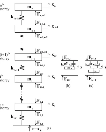
The building model is represented by ann-storey structure, reduced to an-DOF lumped mass system as shown in Figure1(a). Two control systems are proposed, a classical TMD and a new type of vibration suppression system formed of an inerter, a spring and a damper — the TID. The control systems are modelled between adjacent storeys and they are shown in Figures 1(b) and 1(c) respectively.
In order to write the equations of motion for then-DOF structure, the storeys are divided in three categories:
(i) the bottom storey, connected to the ground,i= 1;
(ii) theith
storey,i∈[2 :n−1]; (iii) the top storey,i=n.
The equations of motion for the system in Figure 1are written in absolute coordi-nates as
(m1s2+k0,1+k1,2)X1=k1,2X2+k0,1R+F1,0−F1,2
.. .
(mis2+ki−1,i+ki,i+1)Xi=ki−1,iXi−1+ki,i+1Xi+1+Fi,i−1−Fi,i+1
.. .
(mns2+kn−1,n)Xn=kn−1,nXn−1+Fn,n−1
(3) wheremi andki−1,i, i ∈ [1 : n]represent the mass concentrated on theith storey
and the structural stiffness between storeysi−1andi, respectively;Xirepresents the
Laplace transform of theith
storey displacement;Fi,i−1 represents the force exerted
by the a control device located between storeysi−1andion theith
mass andFi,i+1
represents the force exerted by the a control device located between storeysiandi+ 1 on theith
kd m
cd
m
k
xn
r=x (a)
m xn-1
m
k
xi+1
m xi
m
k
x1
F0,1
F1,0
F1,2
Fi,i-1
Fi,i+1
Fi+1,i
Fi+1,i+2
Fn-1,n-2
Fn-1,n
Fn,n-1
d
Fi+1,i
Fi,i+1 y
bd
Fi+1,i
(b) (c)
0,1
0 i,i+1
n-1,n
1 i i+1 n-1 n
d cd
y k
storey (i+1)th
storey
Fi,i+1 ith
storey nth
storey
1st
Figure 1: (a) Structural System; (b) traditional tuned mass damper system; (c) tuned inerter damper system.
2.2
Traditional tuned mass damper vibration suppression system
We will first study the behaviour of classical TMD systems, and write the generalised expressions of the control forces generated. For the TMD system acting on theith
floor, the control forces can be written in the Laplace domain as
Fi,i+1 = 0 (4a)
Fi+1,i= (kd+cds)(Y −Xi+1) (4b)
wherekdandcd are the stiffness and damping of the TMD respectively,Xi+1is the
Laplace transform of the displacement ofmi+1andY represents the Laplace transform
of the TMD mass displacement. Note that we includeFi,i+1 as it is useful when
comparing with the TID device and writing the generalised device equations. The equation of motion for they-DOF is given by
Y = cds+kd
mds2+cds+kd
Xi+1 (5)
wheremdis the TMD mass. Substituting Equation5in Equation4bit follows that
Fi,i+1= 0 (6a)
Fi+1,i=−
mds2(cds+kd)
mds2+cds+kd
[image:6.612.220.391.120.334.2]Equations6aand6bgive the expressions of the control forces obtained when placing a TMD between storeysiandi+ 1, namelyFi,i+1andFi+1,iacting onmiandmi+1
respectively.
2.3
TID vibration suppression system
If an inerter-based system is mounted at theith
storey level, the control forces can be written in the Laplace domain as
Fi,i+1 =bds2(Xi−Y) (7a)
Fi+1,i= (kd+cds)(Y −Xi+1) (7b)
wherebdrepresents the inertance andXirepresents the Laplace transform of the
dis-placement of massmi. The other quantities were defined earlier. Note that now, due
to the need for an anchor, the inerter forces are exerted on both the upper and lower storey. The equation of motion for they-DOF is given by
Y =bds
2X
i+ (cds+kd)Xi+1
bds2+cds+kd
(8)
Substituting Equation8into Equation7ait follows that
Fi,i+1=
bds2(cds+kd)
bds2+cds+kd
(Xi−Xi+1) (9a)
Fi+1,i=Fi,i+1 (9b)
Equations9aand9bgive the expressions of the control forces obtained when placing an inerter-based control system between storeysiandi+ 1, namelyFi,i+1andFi+1,i
acting onmiandmi+1respectively. Both forces are non-zero.
2.4
Generalised system
The control forces can be written in a general form, regardless the device used.
Fi,i+1 =li,i+1Tddi+1(Xi−Xi+1)
Fi+1,i =li,i+1Td(di+1Xi−Xi+1)
(10)
whereTd=
ˆ
mds2(cds+kd)
ˆ
mds2+cds+kd
,mˆd =mdormˆd =bd for the TMD and TID
respec-tively. Note that fori = 0,X0 = R. In addition,li,i+1 anddi+1 are switches that
allow us to generalise the device and indicate the location and type of device used respectively. Specifically,
(
li,i+1 = 1, if there is a control device situated between storeysiandi+ 1
li,i+1 = 0, otherwise
and
(
di+1 = 1, if the control system is represented by an inerter between storeysiandi+ 1
di+1 = 0, if the control system is a TMD between storeysiandi+ 1
(12) Now, we can combine the device(s) by using Equations10to eliminate the control forcesFi,i+1from Equation3. Therefore, we obtain a system ofncoupled equations
withnunknowns, which are the displacements on each DOF (Equation13).
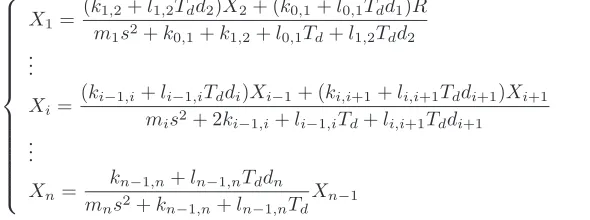
X1=
(k1,2+l1,2Tdd2)X2+ (k0,1+l0,1Tdd1)R
m1s2+k0,1+k1,2+l0,1Td+l1,2Tdd2
.. .
Xi=
(ki−1,i+li−1,iTddi)Xi−1+ (ki,i+1+li,i+1Tddi+1)Xi+1
mis2+ 2ki−1,i+li−1,iTd+li,i+1Tddi+1
.. .
Xn=
kn−1,n+ln−1,nTddn
mns2+kn−1,n+ln−1,nTd Xn−1
(13)
Note that the displacement of thenthstorey depends on the displacement of the storey
below only, while the displacement of a middle storey depends on those of the storey bellow and of the storey above. Therefore, if we substitute the expression ofXnfrom
the(n−1)th
equation into thenth
equation,Xn−1will become a function ofXn−2
only. Successively, following the same procedure, anyXi displacement will depend
onXi−1 only, fori = 2...n. For the bottom storey, we obtainX1 as a function of R, the ground displacement. AfterX1 is computed, all the other displacements are
determined.
In order to account for structural damping as well, Equation13may be updated by replacingki,i+1 withki,i+1+ci,i+1s, whereci,i+1 represents the structural damping
between storeysiandi+ 1.
3
Tuning of the tuned inerter damper system
First we will consider a SDOF system, subjected to sinusoidal ground displacement
r(t) = sin(ωt). The uncontrolled system is shown in Figure2(a). The TMD controlled structure is formed combining the systems in Figure2(a) and 2(b), while the TID controlled structure is formed combining the systems in Figure2(a) and 2(c).
kd m
cd
r=x (a)
m
k
x
F0,1 F1,0
d
F1,0
y kd
b
cd
d
F1,0
y
(b) (c)
F 0,1=0 F 0,1 0,1
1
0 1
[image:8.612.152.447.234.344.2]The most important aspect in the control system design is the appropriate choice of parameters for all the devices considered. In the case of the TMD systems, optimal tuning rules were established by Den Hartog [34] for a single DOF system, for both un-damped and un-damped vibration absorbers. Den Hartog tuning rules adapted to constant acceleration amplitude base-excited structures (according to [25]) are given below
md =µmm1;kd=
µm
(1 +µm)2
k0,1;ζ=
s 3µm
8(1 +µm)
;cd= 2ζ
r
kd
md
md; (14)
wheremd,kdandcdare the TMD mass, stiffness and damping respectively, andζis
the TMD damping coefficient.µmis the TMD mass ratio, and it is typically chosen in
the range1%−10%.
Many applications of the inerter have been studied. However, these refer mainly to vibration isolation. Therefore, there are no generally accepted tuning rules suitable for vibration suppression. Smith [1] gives tuning guidelines for inerters used as vibration isolators, specifically in vehicle suspension systems. Such vibration isolation tuning rules do not lead to satisfactory tuning for vibration suppression applications.
Given the similarity between the TMDs and the TIDs, we propose new vibration suppression system tuning rules based on those established for mass-based systems. Den Hartog [34] shows that for an undamped structure, regardless of the choice of TMD stiffness and damping parameters, all displacement response curves in the fre-quency response diagram pass through two fixed points, P and Q. Moreover, the fixed points location is influenced by stiffness only and is invariant to damping. The frequen-cies where these points occur are determined analytically, solving a quadratic equation in frequency squared, based on the transfer function between the structural and ground displacements. The stiffness,kd, is then selected such that the amplitude of response
of points P and Q is the same, resulting in thekdexpression in Equation14. Finally,
damping, cd, is selected such that, through one of these points, the gradient of the
displacement response curve is zero — this leads to the damping expression in Equa-tion14.
Following a similar procedure, we firstly show that in the case of TIDs, a third fixed point exists, which we denote as V. Considering the SDOF TID controlled structure, formed by combining the systems in Figure2(a) and (c), and using Equation13, the transfer functionX−Rcan be written in the frequency domain as
X R(jω) =
k0,1+Td(jω)
−m1ω2+k0,1+Td(jω)
(15)
whereTd(jω) = −
mdω2(cdjω+kd)
−mdω2+cdjω+kd
andj = √−1. In order to evaluate the re-sponse amplitude, the real and imaginary terms are regrouped and Equation15is ex-pressed in the form
X R(jω) =
A+Bj
C+Dj , hence
X R
2
= A
2
+B2
whereA = k0,1kd −k0,1bdω2−bdω2kd, B = cdω(k0,1 −bdω2), C = (k0,1 −
m1ω2)(kd−bdω2)−kdbdω2, andD =cdω(k0,1−m1ω2−bdω2). Replacingbd =
µbm1andkd =αµbk0,1and regrouping the terms in function ofcdwe obtain
X
R
2
= (αµbk
2
0,1−µbω2k0,1m1−µ2bαω2k0,1m1)2+c2dω2(k0,1−µbω2m1)2
[(k0,1−m1ω2)(αµbk0,1−µbm1ω2)−αµ2bω2k0,1m1]2+c2dω2(k0,1−ω2m1−µbω2m1)2
(17) whereαis a scalar coefficient andµb =bd/m1represents the inertance-to-structural
mass ratio. Note thatµbwill be referred to as theinertance-to-mass ratio.
Reformulat-ing,
X
R =
s
E+F c2
d
G+Hc2
d
(18)
whereE = (k0,1kd−k0,1bdω2−bdkdω2)2,F =ω2(k0,1−bdω2)2,G= ((k0,1−
m1ω2)(kd−bdω2)−kdbdω2)2andH =ω2(k0,1−m1ω2−bdω2)2.
As our objective is to find the coordinates of fixed points, independent of device damping,cd, as in Den Hartog’s derivation [34], the following condition must be
en-forced
E
G =
F
H (19)
Solving Equation19leads to the following cubic equation inω2
µbm31ω 6
−2(1+µb+µbα+µ2bα)m
2
1k0,1ω4+2(1+α+2µbα)m1k0,1ω2−2α= 0 (20)
Solutions to Equation 20, giving the frequencies at which the fixed points are lo-cated, can be computed — note that for TMDs, the equivalent equivalent equation is a quadratic inω2
leading to two damping-invariant points. Solving Equation20
numerically shows that the first two points are located at low frequencies, situated in the vicinity of the fundamental frequency of the uncontrolled structure and the third point is situated at higher frequencies, where the response has low amplitude. Given the point locations, even though we have three fixed points, the ordinate of the highest frequency fixed point can never exceed those of the two low frequency fixed points. Based on Den Hartog’s TMD tuning guidelines, we therefore propose the following TID tuning strategy.
STEP 1 Specify the desired inertance-to-mass ratio,µb;
STEP 2 Iterate stiffness,kd, such that the lower frequency points, P and Q, have equal
ordinates. The initialkdvalue is based on the TMD tuning rules given in
Equa-tion14;
STEP 3 Find the location of the three fixed points that are independent of damping: P, Q and V. This is done by solving Equation20;
STEP 4 Choose damping,cd, such that the displacement response has a zero gradient
We now present a numerical example. The structure is defined by the following parameters
m1= 1 kNs2/m;k0,1= 5000 kN/m; (21)
such thatωn= 11.25 Hz. Using the mass ratioµm= 0.1, the TMD system parameters
used in this application are
kd= 413 kN/m;ζ= 0.18;cd= 2.37 kNs/m; (22)
wherekd,ζandcdare selected using Equation14.
The TID system is tuned according to the method explained, following the steps above. Firstly, we chose the inertance-to-mass ratio,µb = 0.1, keeping it equal to the
TMD mass ratio. Secondly, the stiffness,kd, is selected such that the lower frequency
points, P and Q, have equal ordinates. The TMD tuning rule forkd given in Equation
14was used as an initial guess. Therefore, starting from,kd = 413 kN/m, we
iter-ated STEP 2 until we found the value at which points P and Q have equal ordinates,
kd = 434 kN/m. Then, the coordinates of the fixed points are determined numerically
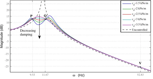
from Equation20: ωP = 9.53 Hz,ωQ = 11.67 HzandωV = 52.83 Hz. Finally, we
calculate the structure frequency response for several damping values shown in Fig-ure3, from whichcd= 2.5 kNs/mis selected as the optimal damping value.
9.53 11.67 52.83
-25 -20 -15 -10 -5 0 5 10 15 20 25
Magnitude (dB)
ω (Hz)
cd=1.5 kNs/m
cd=2 kNs/m
cd=2.5 kNs/m
cd=3 kNs/m
cd=3.5 kNs/m
Uncontrolled P
V Decreasing
[image:11.612.179.435.383.516.2]damping Q
Figure 3: Choice of optimal damping for the TID system forµb= 0.1.
Therefore, the numerical values employed are
µb= 0.1;kd= 434 kN/m;cd= 2.5 kNs/m; (23)
102 103 -60
-40 -20 0 20 40 60
Magnitude (dB)
ω (rad/sec)
Uncontrolled
TMD
TID
7.48 7.5 7.52 7.54 7.56 7.58 -4
-2 0 2 4
t (s)
X/R (-)
7.7 7.72 7.74 -0.02
0 0.02
t (s)
X/R (-)
7.6 7.7 7.8 7.9 -1
0 1
t (s)
X/R (-)
r=sin(ω
n t)
r=sin(160π t)
[image:12.612.175.433.142.292.2]r=sin(10π t)
Figure 4: Systems performance comparison forµm=µb= 0.1.
However, as detailed in Section2, the inertance-to-structural mass ratio,µb, can
be set to high values via gearing, as opposed to increased added mass which results in an improved response. Figure5, shows the steady state frequency response of the structure forµb = [0.1; 0.25; 0.5]andµm= 0.1. As seen, the displacements decrease
asµbincreases. Given the performance of the TID controlled system, we can conclude
that this represents a viable alternative to TMD devices for 1DOF structures.
5 10 15 20 25 30
0 1 2 3 4 5 6 7 8 9 10
ω (Hz)
max(x/r) (-)
Uncontrolled TID µb=0.1
TID µb=0.25
TID µb=0.5
TMD µm=0.1
Figure 5: Maximum absolute displacement forµb = [0.1; 0.25; 0.5]andµm = 0.1;
forµb = 0.25,kd = 896 kN/mandcd = 8.5 kNs/m, while forµb = 0.5,kd =
1333 kN/mandcd= 20 kNs/m.
[image:12.612.178.428.434.585.2]4
MDOF system
We now consider an n-DOF structure subjected to sinusoidal ground displacement,
r(t) = sin(ωt). The structure is shown in Figure1and described by
M=
m1 0 . . . 0
0 m2 . . . 0
..
. ... . .. ...
0 0 . . . mn
,K=
k0,1+k1,2 −k1,2 0 . . . 0
−k1,2 k1,2+k2,3 −k2,3 . . . 0
0 −k2,3 k2,3+k3,4 . . . ...
..
. ... ... . .. −kn−1,n
0 0 . . . −kn−1,n kn−1,n
(24) In this application, the structural damping is considered equal to zero since its value is typically small compared to the control device damping. Moreover, this choice keeps the structural system similar to the one proposed by Den Hartog.
4.1
Modal analysis — A discussion on TID optimal location
It is well known that TMD systems work more efficiently when located near the top of the structure. This is because the largest displacements generally occur at the top of the structure. We now consider whether the same is true for the TID systems when targeting the first mode of vibration. For this, we analyse the modal response of the controlled structures. The equation of motion for then-DOF controlled structure, in matrix form, in the Laplace domain is
Ms2
Z+KZ=−M
1 1 .. . 1 1 s2 R+
F1,0−F1,2
F2,1−F2,3
.. .
Fn−1,n−2−Fn−1,n Fn,n−1
(25)
whereZ = X−Rrepresents the vector of relative storey displacements. Although,
L(¨r) =s2
L(r)−sr(0)−r˙(0), and for sinusoidal inputr˙(0) = 1, for this derivation we consideredL(¨r) =s2
L(r) =s2R
.
Using the transformationZ = ΦQ, whereΦrepresents the eigenvectors matrix, and pre-multiplying both sides byΦT, we obtain
MMMs2
Q+KKKQ=−ΦTM
1 1 .. . 1 1 s2
R+ ΦT
F1,0−F1,2
F2,1−F2,3
.. .
Fn−1,n−2−Fn−1,n Fn,n−1
(26)
whereMMM= ΦTMΦ
andKKK= ΦTKΦ
Using the generalised formulation for the device forces from Equations 10 and performing the transformation from absolute to relative coordinates, the forces vector on the right hand side can be written as
F1,0−F1,2
F2,1−F2,3
.. .
Fn−1,n−2−Fn−1,n Fn,n−1
=Td
l0,1(d1−1)
l1,2(d2−1)
.. .
ln−2,n−1(dn−1−1) ln−1,n(dn−1)
R+. . .
. . .+T d
−l0,1−l1,2d2 l1,2d2 0 . . . 0
l1,2d2 −l1,2−l2,3d3 l2,3d3 . . . 0
0 l2,3d3 −l2,3−l3,4d4 . . . 0
..
. ... ... . .. ...
0 0 . . . ln−1,ndn −ln−1,ndn
Z1 Z2 .. .
Zn−1
Zn (27) Note that in the case when TID control systems are used,di+1 = 1and therefore
the control forces are independent of the ground displacement,R, as the first term on the right hand side of Equation27becomes null.
Now, Equation27is considered for each of the four controlled structures and the results are substituted into Equation26. Then, assuming that only the contribution of the first vibration mode is significant, we obtain the following transfer functions between the modal displacements of the first vibration mode and ground displacement, for each controlled structure.
(i) TMD system located at bottom storey level;
Q1 R = − n P i=1
(miΦi,1)s2−Φ1,1Td
mm1s2+km1+TdΦ21,1
(28)
(ii) TMD system located at top storey level;
Q1 R = − n P i=1
(miΦi,1)s2−Φn,1Td
mm1s2+km1+TdΦ2n,1
(29)
(iii) TID system located at bottom storey level;
Q1 R = − n P i=1
(miΦi,1)s2
mm1s2+km1+TdΦ21,1
(30)
(iv) TID system located at top storey level;
Q1 R = − n P i=1
(miΦi,1)s2
mm1s2+km1+Td(Φn−1,1−Φn,1)
(v) Damper system located at bottom storey level - This results in a transfer fuction identical with the one in Equations30.This is because both systems are located at bottom storey level. The difference consists in the control device transfer
function, which for a TID isTd=
ˆbds2(c
ds+kd)
ˆbds2+c
ds+kd
, while for a viscous damper
it isTd=cds, wherecdrepresents damping.
wheremmi,i = 1. . . nrepresent the modal masses andkm1 is the modal stiffness
of the first vibration mode, Φi,1 represent the components of the first mode shape,
Φ1= [Φ1,1,Φ2,1, . . . ,Φn,1], andQ1represents the Laplace transform of the
displace-ment of the first vibration mode. Taking into account the fact that|Φ1,1| <|Φ2,1| <
. . . < |Φn,1|and analysing the modal displacement-to-ground displacement transfer
functions given in Equations28-31, provided there is no significant modal interaction, it can be seen that:
(i) The fact that the top TMD is more efficient than the bottom one is verified by Equations28and29, since theΦ2
n,1term located at the latter’s denominator is
much larger thanΦ2
1,1, present in the former equation. Therefore, the modal
displacement will be smaller if the TMD is located at the top of the structure;
(ii) Comparing denominators on the right hand side of Equations29and31, we no-tice that the latter is smaller as it contains a relative term, namely(Φn−1,1 −
Φn,1)2, while the former is the largest component of the eigenvector, Φ2n,1.
Therefore, the system performance is impaired if the same control systems char-acteristics, contained inTd, are kept. In order to have identical response on the
first mode of vibration we need to scale the TID system according to the ratio Φ2
n,1/(Φn−1,1−Φn,1)2. This has been verified numerically and is shown in the
numerical example;
(iii) Looking at Equations30and31it is seen that numerators are identical, while the latter denominator is much lower due to the presence of the relative term. This indicates that the response will be improved if the TID is placed at the bottom storey of the structure. Similarly to (ii), the ratioΦ2
1,1/(Φn−1,1−Φn,1)
2
indicates that the TID placed at the top of the structure must be over-designed with respect to the TID placed at bottom level in order to obtain identical performance. This has been verified numerically and is shown in the numerical example;
(iv) Analysing Equations28-31and the remarks above we can conclude that the TID displays a TMD-like behaviour in the vicinity of the first fundamental frequency, due to the similarity between the transfer functions of the two devices. At higher frequencies, we note that Td → cd regardless the type of control system
4.2
Traditional tuned mass damper
&
tuned inerter damper
sys-tem tuning
The TMD system is tuned according to Den Hartog’s guidelines, given in Equation14, regardless of the device location. These have been adapted to multiple DOF structures, to target the first mode of vibration.
md=µmmef f;kd=ω12
µm
(1 +µm)2
md;ζ=
s 3µm
8(1 +µm)
;cd = 2ζ
r
kd
md
md;
(32) whereω1represents the first fundamental frequency. Please note that the TMD mass
is computed as a fraction ofmef f, the effective modal mass participating in the first
mode.
The TID system is tuned following the procedure described in3and will be detailed in a numerical example in the following subsection.
4.3
Numerical application
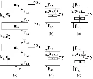
All results derived previously, in section4, are exemplified in a3-DOF system shown in Figure6, wherem1=m2=m3= 1 kNs2/mandk0,1=k1,2=k2,3= 1500 kN/m.
The numerical values were selected for convenience, while retaining realistic natural frequencies and noting that the parameters scale linearly. As seen in Figure6, device configurations are considered by modelling each control system (6(b)-6(e)) inside the uncontrolled structure shown in Figure6(a). Note that only one control system is used at a time.
kd
m
cd
k
r
(a)
m
k
x3
m x2
m
k
x
F0,1 F1,0 F1,2 F2,1 F2,3 F3,2
d
F1,0
y kd b cd d
F1,0
y
(b) (c)
(d) (e)
F0,1 F0,1 1
kd m
cd d
F3,2
y kd b cd d
F2,3
y
F2,3 F2,3
0,1 1 2 3
1,2 2,3
Figure 6: (a) Structural system 3DOF; (b) TMD located at top storey level; (c) TID located at top storey level; (d) TMD located at bottom storey level; (e) TID located at bottom storey level.
The components of the first mode shape, Φ1 = [Φ1,1,Φ2,1,Φ3,1] are Φ1,1 =
−0.543, Φ2,1 = −0.979and Φ3,1 = −1.22. We will first study the optimal
[image:16.612.228.384.432.564.2]to have identical response for top TID and TMD on the first mode of vibration, we need to enforceµb ≈25µm, with the same scaling applied to the TID system’s
stiff-ness and damping. This is shown in Figure7(a). Note that the response curves are not identical since the extra numerator term for the TMD, see Equation29, has not been taken into consideration. Then, looking at Equations30and31, we notice that Φ2
1,1/(Φ2,1−Φ3,1)2≈5which indicates that in order to obtain identical performance,
the TID placed at the top of the structures has to be designed to a capacity that is5 times larger than that of a TID placed at bottom level. This is shown in Figure7(b).
7.55 7.6 7.65 7.7 7.75 7.8 7.85 7.9
-8 -6 -4 -2 0 2 4 6 8
(a)
t (s)
x/r (-)
x 1 TMD top x
2 TMD top x
3 TMD top x
1 TID top x
2 TID top x
3 TID top
7.55 7.6 7.65 7.7 7.75 7.8 7.85 7.9
-8 -6 -4 -2 0 2 4 6 8
(b)
t (s)
x/r (-)
x 1 TID bottom x
2 TID bottom x
3 TID bottom x
1 TID top x
2 TID top x
3 TID top
Figure 7: Displacement comparison: (a) TMD top: md,kd,cd and TID top: 25md,
25kd,25cdand (b) TID bottom:bd,kd,cdand TID top:5bd,5kd,5cd.
Following the remarks above, that have been verified in Figure7, we conclude that, in contrast to TMDs, placing a TID at bottom storey level is more efficient that placing it at the top. This is a clear advantage of the TID over the TMD as the weight of the device does not need to be supported by the whole structure.
We have analysed the displacement response of all four control systems. The results in Figures7(a) and7(b), suggest that in order to obtain similar performance to a TMD located at the top of the structure, a bottom located TID must have roughly5 times the capacity of the TMD. The inertance-to-mass ratio,µb, can have higher values than
the TMD mass ratio, µm. This is achievable via gearing. The following numerical
parameters are proposed for the control systems elements, based on the tuning rules discussed in Section3. The viscous damper located at bottom storey level was tuned such that it displays similar displacement response with the TID and TMD systems in the vicinity of the first fundamental frequency.
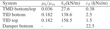
System µb/µm kd(kN/m) cd(kNs/m)
TMD bottom/top 0.036 27.6 0.38 TID bottom 0.182 138.6 2.5
TID top 0.182 158.5 1.5
[image:17.612.156.460.241.368.2]Damper bottom - - 22.5
[image:17.612.192.419.588.651.2]The TID and TMD interter-to-mass and mass ratios are computed with respect to the effective mass participating in the first vibration mode. Therefore, the TMD mass ratio isµm= 3.6%, while the TID inertance-to-mass ration isµb = 18.2%of the mass
participating in the first mode of vibration. Similar and much higher mass ratios have been used before in TMDs [42] and are much easier to achieve with an inerter due to its gearing. There are several options in choosing the modal mass. Another approach is shown in [43].
2 4 6 8 10 12 14
0 10 20 30 40 50 60 70 80
ω (Hz)
max |x
3
/r| (-)
Uncontrolled TID bottom c=1.5kNs/m TID bottom c=2kNs/m TID bottom c=2.5kNs/m TID bottom c=3kNs/m
2.2 2.4 2.6 2.8 3 4
6 8 10
7.2 7.4 7.6 7.8 8 8.2 4
6 8 10 12 14
10.6 10.8 11 11.2 11.4 11.6 2
4 6 8
[image:18.612.156.457.226.375.2]P Q
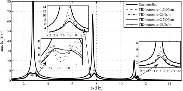
Figure 8: Normalised maximum absolute displacements for TID bottom:µb= 0.182,
kd = 138.6 kN/mand optimal damping iscd= 2.5 kNs/m.
2 4 6 8 10 12 14
0 10 20 30 40 50 60 70 80
ω (Hz)
max |x
3
/r| (-)
Uncontrolled TID top c=0.5kNs/m TID top c=1kNs/m TID top c=1.5kNs/m TID top c=2kNs/m
2.4 2.6 2.8 3 5
10 15 20 25
7.6 7.8 8 8.2 5
10 15 20 25
10.610.8 11 11.211.411.6 2
4 6
[image:18.612.159.457.448.599.2]P Q
Figure 9: Normalised maximum absolute displacements for TID top: µb = 0.182,
kd = 158.5 kN/mand optimal damping iscd= 1.5 kNs/m.
2 4 6 8 10 12 14 0
10 20 30 40 50 60 70 80
ω (Hz)
max |x
3
/r| (-)
2.4 2.6 2.8 3 3.2 10
20 30 40
7 7.5 8
0 20 40
10.610.8 11 11.211.411.6 0
10 20
[image:19.612.150.450.128.286.2]Uncontrolled TID bottom TMD top
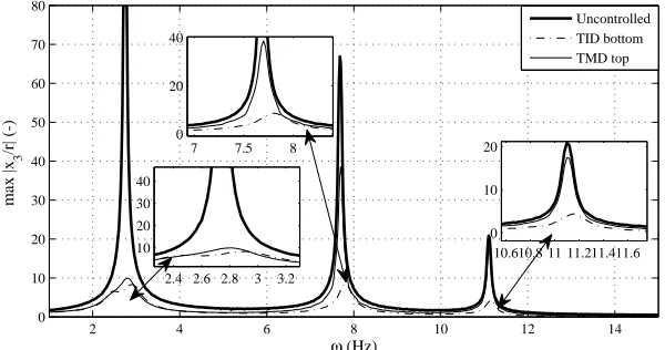
Figure 10: Normalised maximum absolute displacements forµm = 0.036andµb =
0.182.
placed at bottom storey level. The first two fixed points,P andQ, are shown in the zoom-in done in the vicinity of the first fundamental frequency of the uncontrolled system. We highlight the points by plotting a range of damping values including the optimal one found using the tuning rules. The other two zoom-ins allow us to observe the structural response in the vicinity of the second and third natural frequencies. The curve that has a horizontal tangent through one of the two fixed points is that obtained whencd = 2.5 kNs/m. If damping is further increased, the response is amplified.
Similarly, the case when the TID is placed at the top of the structure is shown in Figure
9.
4.4
Performance assessment of TID systems
Figure10shows the frequency response of all four TMD and TID control systems, em-ploying the optimal parameters presented in Table1. The best performance is achieved when the TID is placed at lower level, while the TMD in the same location offers the poorest results. If a TMD is placed at top storey level, the response obtained is similar to that of the TID placed at the bottom storey level. The response obtained by placing a TID at upper story level is also satisfactory. Also note that the TID systems do not create resonant peaks in the vicinity of the second and third fundamental frequencies, hence the TID is capable of suppressing the response of all three modes, and not only of the one initially targeted, as in the case of TMDs. The inerter or mass-related dis-placement,y (see Figure6), has also been evaluated over the same frequency range for the best performing systems, TID located at bottom storey level and TMD located at top storey level. The two systems have similar displacements in the vicinity of the first fundamental frequency,2.74Hz. However, in contrast to the TMD, the TID de-sign results in smally-displacement in the vicinity of the second and third fundamental frequencies,7.7Hzand11.1Hzrespectively.
calculated the level of the maximum absolute forces in the spring (Fcd) and the damper
(Fkd) and the overall control force (F) for the case when the systems is forced in
the vicinity of the first fundamental frequency. These are given in Table2. For a better assessment of the TID performance, we have included the control force in an equivalent viscous damper mounted at bottom storey level. Its characteristics are given in1.
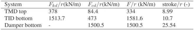
System Fkd/r(kN/m) Fcd/r(kN/m) F/r(kN/m) stroke/r(-)
TMD top 378 84.4 334 8.99
TID bottom 1513.7 473 1581.6 10.7
[image:20.612.141.470.195.247.2]Damper bottom - 1500.5 1500.5 25.54
Table 2: Maximum efforts in TMD, TID and damper system elements and overall control forces.
From Table2it can be seen that the spring force is approximately5.4times larger for the TID, which is consistent with the ratio between the stiffness of the two control systems. The force in the dampers is3.3larger in the case of the TID, while the ratio between their actual damping is2.4. The overall maximum absolute control force generated by the TID is4.5times larger than that generated by the TMD. The control force produced by the damper system is similar to that of the TID system. Please note that if the system is excited at higher frequencies, the damper control force becomes very large in comparison to those of the TID and TMD systems. The interstorey drifts and floor accelerations have also been computed. All three control systems displayed similar performance near the first fundamental frequency. In the vicinity of the second and third fundamental frequency, the TMD system is ineffective, leading to a response similar to that of the uncontrolled structure. The TID and damper systems ensure a good level of vibration suppression, the latter being the most efficient. However, this is done at the expense of a much higher control force (up to5times larger than the TID control force).
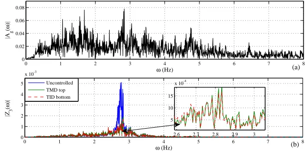
The 3 DOF structure has also been subjected to earthquake base excitation. We have chosen a ground acceleration recording from the Tohoku earthquake that took place in Japan on the 11th of March, 2011 which is represented in Figure 11(a).
For this section, the structural damping is no longer kept null, but set to a low damp-ing coefficient of2%. All other structural parameters are left unchanged, the control systems being tuned optimally (Table1). Figure11(b) shows the displacement time history on the upper DOF. Three zoom-in plots are included in the regions where the displacement response is amplified. The results obtained in case of sinusoidal ground excitation are confirmed in case of earthquake excitation. The displacement response obtained with the bottom placed TID is similar to that obtained using a TMD at the top of the structure.
0 20 40 60 80 100 120 140 160 180 -0.1
-0.05 0 0.05
t (s)
max( |z
3
| ) (m)
(b)
41 41.5 42 -0.04
0 0.04
85 85.5 86 -0.05
0 0.05
154 154.5 -0.02
0 0.02
0 20 40 60 80 100 120 140 160 180
-4 -2 0 2 4
t (s) ag
(m/s
2)
(a)
Uncontrolled TMD top TID bottom
Figure 11: (a)Ground acceleration time-history and (b)Relative displacement time his-tory with2%structural damping.
of the the chosen ground motion. Therefore, the structure is sensitive to the earthquake chosen. The Fourier spectra show the same performance hierarchy.
0 1 2 3 4 5 6 7 8
0 0.02 0.04 0.06 0.08
ω (Hz)
|A
g
(
ω
)|
(a)
0 1 2 3 4 5 6 7 8
0 1 2 3 4 5
x 10-3
ω (Hz) |Z3
(
ω
)|
(b)
Uncontrolled TMD top TID bottom
2.6 2.7 2.8 2.9 3
5 10 15
[image:21.612.151.463.125.293.2]x 10-4
Figure 12: Single sided Fourier spectra: (a) of the ground acceleration and (b) of the displacement response.
[image:21.612.152.458.398.551.2]4.5
Discussion on TID design for high-rise buildings
In the case of high-rise buildings, the control forces necessary for suppressing un-wanted vibrations become larger. We will consider this through an analysis of a6-DOF and a10-DOF structure, defined according to Section4and employing the same nu-merical values formi andki,i = 1. . . n. We will only refer to the best performing
systems, the TMD top and TID bottom. Inspecting Equations29and30, we notice that the poles of the two transfer functions are the same provided that the control device transfer fuction,Tdfor the TID is scaled byφ2n,1/φ
2 1,1.
n 1 3 6 10
φ2
n,1/φ 2
[image:22.612.226.384.241.267.2]1,1 1 5.04 17.2 44.7
Table 3:φ2
n,1/φ 2
1,1ratio forn= 1,3,6,10
The ratiosφ2
n,1/φ 2
1,1are given in Table3. This ratio therefore provides an
approxi-mate effective inertance-to-mass ratio between the devices — see Section4. This might appear unfavourable for the TID, but we recall the fact that existing inerter devices built ttain an inertance-to-physical mass ratio of approximately200[44] - well above that required here. Therefore, TIDs located at bottom storey level remain a feasible alter-native to TMDs.
5
Conclusions
6
Acknowledgements
The authors would like to acknowledge the support of the EPSRC and the University of Bristol: S. A. Neild is supported by an EPSRC fellowship EP/K005375/1, D.J. Wagg is supproted by EP/K003836/1 and I. F. Lazar is supported by a University of Bristol studentship.
References
[1] Smith MC. Synthesis of Mechanical Networks: The Inerter.IEEE Transactions on Automatic Control2002;47:1648-1662.
[2] Chen MZQ, Papageorgiou C, Scheibe F, Wang F-C, Smith MC. The missing me-chanical circuit.IEEE Circuits and Systems Magazine2009;1531-636X:10-26.
[3] Wang F-C, Hong M-F, Lin T-C. Designing and testing a hydraulic inerter. Pro-ceedings of the Institution of Mechanical Engineers, Part C: Journal of mechanical Engineering Science2010,225:66-72.
[4] Wang F-C, Lin T-C, Hydraulic inerter mechanism,Patent Application Publication, No 0139225A1, USA, 2009.
[5] Papageorgiou C, Smith MC, Laboratory experimental testing of inerters. 44th IEEE Conference on Decision and Control and the European Control Conference. Seville, Spain 2005; 3351-3356.
[6] Papageorgiou C, Houghton NE, Smith MC. Experimental Testing and Analysis of Inerter Devices.Journal of Dynamic Systems, Measurement and Control, ASME 2009;131::011001-1 - 011001-11.
[7] Kuznetsov A, Mammadov M, Sultan I, Hajilarov E. Optimization of improved sus-pension system with inerter device of the quarter-car model in vibration analysis. Arch. Applied Mechanics2011;81:1427-1437.
[8] Scheibe F, Smith MC, Analytical solutions for optimal ride comfort and tyre grip for passive vehicle suspensions.Journal of Vehicle System Dynamics2009;
47:1229-1252.
[9] Smith MC, Wang F-C. Performance benefits in passive vehicle suspensions em-ploying inerters.Journal of Vehicle System Dynamics2004;42:235-257.
[10] Wang F-C, Su W-J. Impact of inerter nonlinearities on vehicle suspension control. International Journal of Vehicle Mechanics and Mobility2008,46:575-595.
[12] Wang F-C, Liao M-K, Liao B-H, Su W-J, Chan H-A. The performance improve-ments of train suspension systems with mechanical networks employing inerters. International Journal of Vehicle Mechanics and Mobility, Vol. 47, 805-830, 2009.
[13] Evangelou S, Limebeer DJN, Sharp RS, Smith MC. Mechanical steering com-pensators for high-performance motorcycles.Transactions of the ASME, Vol. 74, 332-346, 2007.
[14] Preumont A. Vibration Control of Active Structures, Springer-Verlag, Berlin, 2011.
[15] Wagg DJ, Neild SA.Nonlinear Vibration with Control, Springer-Verlag, Bristol, 2009.
[16] Nagarajaiah S, Sahasrabudhe S. Seismic response control of smart sliding isolated buildings using variable stiffness systems: An experimental and numerical study. Earthquake Engineering and Structural Dynamics2006;35(2):177-197.
[17] Ordonez D, Foti D, Bozzo L. Comparative study of inelastic response of base isolated buildings.Earthquake Engineering and Structural Dynamics2003;
32(1):151-164.
[18] Malhotra PK. Dynamics of seismic impacts in base-isolated buildings. Earth-quake Engineering and Structural Dynamics1997;26(5):515-528.
[19] Taflanidis AA, Jia GF. A simulation-based framework for risk assessment and probabilistic sensitivity analysis of base-isolated structures.Earthquake Engineer-ing and Structural Dynamics2011;40(14):1629-1651.
[20] Hoang N, Warnitchai P. Design of multiple tuned mass dampers by using a numer-ical optimizer.Earthquake Engineering and Structural Dynamics2005; 34 :125-144.
[21] Miranda JC. On tuned mass dampers for reducing the seismic response of struc-tures.Earthquake Engineering and Structural Dynamics2005;34(7):847-865.
[22] Aguirre JJ, Almazan JL, Paul CJ. Optimal control of linear and nonlinear asym-metric structures by means of passive energy dampers.Earthquake Engineering and Structural Dynamics2013;42(3):377-395.
[23] Lavan O. On the efficiency of viscous dampers in reducing various seismic responses of wall structures.Earthquake Engineering and Structural Dynamics 2012;41(12):1673-1692.
[24] Soong TT, Dargush GF.Passive Energy Dissipation Systems in Structural Engi-neering,, John Wiley & Sons, Chichester, England, 1997.
[26] Soong TT, Cimellaro GP. Future directions in structural control.Structural Con-trol and Health Monitoring, Vol. 16, 7-16, 2009.
[27] Wagg DJ , Neild SA. A review of non-linear structural control techniques. Pro-ceedings of the Institution of Mechanical Engineers, Part C: Journal of Mechanical Engineering Science , 2011,225:759770.
[28] F-C. Wang , C-W. Chen, M-K. Liao, M-F. Hong. Performance analyses of build-ing suspension control with inerters.Proceedings of the 46th IEEE Conference on Decision and Control, New Orleans, LA, USA, 3786-3791, 2007.
[29] Wang F-C, Hong M-F, Chen C-W. Building suspensions with inerters. Proceed-ings IMechE, Journal of Mechanical Engineering Science, Vol. 224, 1605-1616, 2009.
[30] Ikago K, Saito K, Inoue N. Seismic control of single-degree-of-freedom structure using tuned viscous mass damper.Earthquake Engineering and Structural Dynam-ics2012;41:453-474.
[31] Sugimura Y, Goto W, Tanizawa H, Saito K, Nimomiya T. Response control effect of steel building structure using tuned viscous mass damper. inProceedings of the 15th World Conference on Earthquake Engineering, Lisbon, Portugal, 2012.
[32] Ikago K, Sugimura Y, Saito K, Inoue K. Modal response characteristics of a multiple-degree-of-freedom structure incorporated with tuned viscous mass damper.Journal of Asian Architecture and Building Engineering2012; 11 :375-382.
[33] Takewaki I, Murakami S, Yoshitomi S, Tsuji M. Fundamental mechanism of earthquake response resuction in buildind structures with inertial dampers. Jour-nal of Structural Control and Health Monitoring2012; textbf19:590-608.
[34] Den Hartog JP.Mechanical Vibrations, McGraw Hill, York, PA, USA, 1940.
[35] Fujino I, Abe M. Design formulas for tuned mass dampers based on a perturbation technique.Earthquake Engineering and Structural Dynamics1993;22:833-854.
[36] Moutinho C. An alternative methodology for designing tuned mass dampers to re-duce seismic vibrations in building structures.Earthquake Engineering and Struc-tural Dynamics2012;41(14):2059-2073.
[37] De Angelis M, Permo S, Reggio A. Dynamic response and optimal design of structures with large mass ratio TMD.Earthquake Engineering and Structural Dy-namics2012;41(1):41-60.
[38] Sadeh F, Mohraz B, Taylor AW, Chung RM. A method for estimating the param-eters of tuned mass dampers for seismic applications.Earthquake Engineering and Structural Dynamics1997;22(6):617-635.
[40] Garner BG , Smith MC.Damping and inertial hydraulic device, Patent Applica-tion PublicaApplica-tion, No US 2013/0037362A1, 2013.
[41] Firestone FA. A new analogy between between mechanical and electrical sys-tems,J. Acoust. Soc. Amer., vol. 4, 249-267, 1933.
[42] De Angelis M, Perno S, Reggio A. Dynamic response and optimal design of struc-tures with large mass ratio TMD.Earthquake Engineering and Structural Dynam-ics2011;41:41-60.
[43] Furuhashi T, Ishimaru S. Mode control seismic design with dynamic mass.14th World Conference on Earthquake Engineering, Beijing, China, 2008.