This is a repository copy of
Development of cryogenic loop heat pipes: A review and
comparative analysis
.
White Rose Research Online URL for this paper:
http://eprints.whiterose.ac.uk/95738/
Version: Accepted Version
Article:
Bai, L, Zhang, L, Lin, G et al. (2 more authors) (2015) Development of cryogenic loop heat
pipes: A review and comparative analysis. Applied Thermal Engineering, 89. pp. 180-191.
ISSN 1873-5606
https://doi.org/10.1016/j.applthermaleng.2015.06.010
© 2015. This manuscript version is made available under the CC-BY-NC-ND 4.0 license
http://creativecommons.org/licenses/by-nc-nd/4.0/
[email protected] https://eprints.whiterose.ac.uk/
Reuse
Unless indicated otherwise, fulltext items are protected by copyright with all rights reserved. The copyright exception in section 29 of the Copyright, Designs and Patents Act 1988 allows the making of a single copy solely for the purpose of non-commercial research or private study within the limits of fair dealing. The publisher or other rights-holder may allow further reproduction and re-use of this version - refer to the White Rose Research Online record for this item. Where records identify the publisher as the copyright holder, users can verify any specific terms of use on the publisher’s website.
Takedown
If you consider content in White Rose Research Online to be in breach of UK law, please notify us by
Development of cryogenic loop heat pipes: a review and
comparative analysis
Lizhan Bai
1,*, Jinghui Guo
1, Guiping Lin
1, Jiang He
2, Dongsheng Wen
31 Laboratory of Fundamental Science on Ergonomics and Environmental Control, School of Aeronautic Science and Engineering, Beihang University, Beijing 100191, PR China
2 Beijing Key Laboratory of Space Thermal Control Technology, Beijing Institute of Spacecraft System Engineering, Beijing 100094, PR China
3 School of Chemical and Process Engineering, University of Leeds, Leeds, LS2 9JT, UK
Abstract: Loop heat pipes(LHP) are highly efficient two-phase heat transfer devices with the ability to
transfer a large amount of heat over a long distance. Due to increasing demand of efficient cryocooling
applications in both space and terrestrial surroundings, LHPs operating in cryogenic temperature range
have been extensively investigated in recent years. This work provided a comprehensive review of
state-of-art cryogenic loop heat pipes (CLHPs) Five different types of CLHP were categorized, and a
comparative analysis between CLHPs and ambient LHPs and among different types of CLHPs were
conducted. The operation and performance characteristics of different types of CLHPs were compared
in terms of the system structure, supercritical startup, heat transport capacity and the effect of parasitic
heat load. The parameters that affect the CLHP performance were analyzed and the optimization
strategy was presented in order to progress their future development and applications .
Keywords: loop heat pipe; cryogenic; supercritical startup; heat transport
* Corresponding author. Tel.: +86 10 8233 8600; fax: +86 10 8233 8600.
1 Introduction
Loop heat pipes (LHPs) are highly efficient two-phase heat transfer devices that utilize the evaporation
and condensation of a working fluid to transfer heat, and capillary forces developed in fine porous wick to
circulate the working fluid[1, 2]. Compared with traditional heat pipes, LHPs have the advantage of
transferring a larger amount of heat over a longer distance with strong antigravity capability. Moreover, the
arrangement of LHP to connect the heat source and heat sink becomes more convenient due to its flexible
transport lines.
A typical LHP is composed of an evaporator, a condenser, a compensation chamber (CC) and vapor and
liquid transport lines. Fig.1 shows the detailed structure of the evaporator and CC, and Fig.2 shows the
schematic view of a typical LHP. The vapor transport line connects the vapor grooves and the condenser
inlet, and the liquid transport line connects the bayonet extending to the evaporator core and the condenser
outlet. The basic working principle and operating characteristics of an LHP were introduced in Ref.[2].
When heat load is applied to the evaporator, liquid is vaporized at the outer surface of the evaporator wick,
and the menisci formed in the evaporator wick develop a capillary pressure to push the vapor collected in
the vapor grooves through the vapor transport line to the condenser, where the fluid condenses and the heat
is rejected to the heat sink. The condensed liquid is pushed back through the liquid transport line to the
evaporator core, which provides liquid replenishment to the evaporator wick to complete the circulation. As
the capillary forces developed in the evaporator wick is the driving source for the circulation of the working
fluid along the loop, no external power is needed in the operation of an LHP.
The development of LHPs was originated in 1972 by the Russian scientists Gerasimov and Maydanik
from the Ural Polytechnical Institute. The first LHP had a transport length of 1.2m and heat transfer
conducted in 1989 aboard the Russian spacecraft “Gorizont”, which demonstrated the serviceability of LHP
in reduced gravity conditions [1]. Since their initial conceptualization, these devices have attracted
considerable interests from researchers worldwide including USA, Canada, China, Japan, Brazil, French
and Australia to develop better space thermal control systems Both experimental and theoretical work
have been conducted, which confirmed that LHPs poesessed good self-startup capability, excellent heat
transfer performance and strong antigravity capability [3-9]. To date, more than one hundred LHPs with
cylindrical evaporators have been applied in the thermal control systems of many spacecraft, and the
number still keeps increasing.
With the rapid development of LHP technology for space applications, its application has been extended
to terrestrial surroundings, such as in the thermal management of aircraft and submarines, and the cooling
of high power-density electronic devices[10-20]. Since most of the heat sources or objects to be cooled
have flat thermo-contact surfaces, LHPs with flat evaporators including both opposite liquid replenishment
and longitudinal liquid replenishment have been developed and tested extensively. It is found that a LHP
with stainless steel-nickel-ammonia combination is the most efficient for temperature range at 40-70 ,
while the copper-copper-water combination performs best at 70-100 range[21].
LHPs mentioned above are are termed as ambient loop heat pipes (ALHPs) as they are operating within
the ambient temperature range; and the working fluids are typically ammonia, water, acetone or methanol,
etc. They are not suitable for cryogenic temperature applications. For instance the thermal control of a
space infrared exploration system requires maintaining the infrared sensors/detectors at 80-100K, and
the cooling of superconducting magnet and small-scale particle detectors on the ground requires even lower
temperature. LHPs operating in the cryogenic temperature range, termed as cryogenic loop heat pipes
The development of CLHP was initiated at the beginning of this century, and considerable achievement
has been obtained . CLHPs with different system structures and operation temperatures have been
developed and investigated both experimentally and theoretically. These devices have been reported to
start successfully at supercritical conditions and operate steadily in the corresponding cryogenic
temperature range. They can be applied in both space and terrestrial surroundings, and the lowest operating
temperature range has been extended to 3-5K. In addition, these devices could provide efficient
cryocooling of both concentrated and large area heat sources.
In this paper, the development of cryogenic loop heat pipes (CLHPs) will be reviewed in detail, and the
operating principle and characteristics as well as the application fields of each type of CLHP will be
comparatively analyzed. This will form understanding of the principal differences among different types
of CLHPs and provide guidance to the design and application of these devices.
2 Cryogenic working fluids
As CLHPs are operating in the cryogenic temperature range, appropriate cryogenic working fluids must
be selected first The available cryogenic working fluids for selection is actually quite limited, and as a
rule of thumb : propane for the operating temperature range of 200-240K, oxygen for 90-140K, nitrogen for
80-110K, neon for 30-40K, hydrogen for 20-30K. When the operating temperature is further reduced to
2-4K, helium will be an appropriate cryogenic working fluid.
The cryogenic working fluids charged into the system determine the operating temperature range, heat
transfer performance, heat transport capacity and the lifespan of the CLHPs. Compared with ambient
working fluids such as ammonia and water, cryogenic working fluids have much smaller surface tension
1.75
0.25 v
v
Du
(1)
Based on the evaluation of the capillary limit, which takes comprehensive thermo-physical properties of the
working fluid into account, a higher Dunbar Parameter will produce a larger heat transport capacity of the
LHP charged with that working fluid.
Fig.3 shows the variation of Dunbar Parameter of ambient working fluids, i.e. ammonia and water, and
Fig.4 shows the variation of Dunbar Parameter of cryogenic working fluids including nitrogen, argon,
oxygen, hydrogen and helium. Comparing Fig.4 with Fig.3, the maximum Dunbar Parameter for ammonia
reaches above 160×109W1.75 at 50 , and a higher number is seen for water at a temperature > 130 .
However the maximum Dunbar Parameters for nitrogen, argon and oxygen are 3.2×10⁹W1.75,
4.4×10⁹W1.75 and 6.3×10⁹W1.75 respectively, and it is reduced to 2.3×10⁶ W1.75 for helium. It is evident that
the cryogenic working fluids have much lower Dunbar Parameter, which will result in reduced heat
transport capacity of CLHPs comparing to ALHPs. This issue must be carefully considered in the design
of CLHPs.
3 Cryogenic loop heat pipes with different types
To date, several types of CLHPs have been developed and investigated both experimentally and
theoretically to satisfy different applications at varying operation temperatures. Five types are
summarized based on the difference of system structure and layout, as reviewed in detail below.
3.1 Type A
3.1.1 System structure
Fig.5 shows the schematics of this type of CLHP, which is composed of an evaporator, a condenser, a
only has one additional gas reservoir, which has the simplest structure among all types of CLHPs.
3.1.2 Supercritical startup
For type A CLHP to realize a supercritical startup, the gravity-assisted method has been proposed. The
gravity-assisted method is to utilize gravity to cool and saturate the evaporator wick of the CLHP without
using any additional components. For type A CLHP, the condenser must be placed higher than the
evaporator during the supercritical startup. A typical startup process is as follows: Prior to the startup,
the whole CLHP is at the ambient state, and the condenser temperature begins to decrease as the
cryogenic heat sink takes effect. Condensation occurs after reaching th local saturation temperature, and
the condensate flow into the evaporator through both the liquid and vapor transport lines due to the effect
of gravity. Once the evaporator wick is fully saturated with liquid, heat load can be applied to the
evaporator to start up the CLHP.
3.1.3 Experimental results
Only very limited work was reported for type A CLHP. Pereira et al.[22] constructed and experimentally
investigated a CLHP as a potential candidate for the cooling of small-scale particle detectors. Noble gases
and propane were selected as the cryogenic working fluids. The outer diameter and length of the cylindrical
evaporator were 18 and 30mm respectively, and the transport distance was 350mm. The condenser and the
liquid and vapor transport lines were all 4mm inner diameter tubes. Both the evaporator and condenser
were made of copper to ensure good thermal conduction between the heat sink and heat source. The CC
and the transport lines were made of stainless steel. The heat sink was provided by an commercial
Gifford-McMahon cryocooler. Experimental results showed that the CLHP could easily realize the
an optimal working fluid inventory for each cryogenic working fluid to achieve the best heat transfer
performance. The heat transport capacity of the CLHP was 20W for argon as the cryogen fluid, and it
increased to 25W and 30W for krypton and propane respectively. Comparing with the gravity-assisted
mode, the operation temperature was much higher when the condenser was nearly level with the
evaporator. r.
3.2 Type B
3.2.1 System structure
Fig.6 shows the schematic of this type of CLHP. Compared with an ALHP, the CLHP has an additional
secondary evaporator in addition to the gas reservoir. The secondary evaporator is attached directly to the
cryogenic heat sink and is connected in series with the condenser line, which separates the condenser line
into two parts. The secondary evaporator is typically like the evaporation section of a traditional grooved
heat pipe, and the wick is made of axial grooves machined directly on the inner surface of the pipe wall.
3.2.2 Supercritical startup
The use of a secondary evaporator, type B, is mainly for the consideration of supercritical startup. A
typical startup process is similar to type A except that additional heat is applied on the secondary evaporator.
The produced vapor push the condensate into the primary evaporator and CC through the liquid and
vapor transport lines. Until the wick is fully saturated with the liquid, heat load is applied to the primary
evaporator to start up the CLHP. As the vapor has no preferable direction to push the condensate, it
cannot establish one-way circulation of the working fluid in the loop. The application of heat load to the
3.2.3 Experimental results
Within this category, Mo et al.[23-25] designed and experimentally investigated a nitrogen-charged
CLHP. The outer diameter and length of the primary evaporator were 20 and 100mm respectively, and the
transport distance was about 170mm. The heat sink was provided by a copper plate cooled by liquid
nitrogen. Experimental results showed that the whole CLHP could be cooled down successfully to the
operation temperature from room temperature under gravity-assistance. When the vapor-liquid interface
was present in the liquid core of the primary evaporator, temperature oscillation was observed under low
power levels. The heat transfer capability of the CLHP increased as the height between the liquid and
vapor lines increased. For instance the heat transfer capability of the CLHP was 8, 11 and 16 W
respectively when the liquid line was 0, 3.4 and 6.4 cm below the vapor line. The gas reservoir volume,
effective pore diameter of the primary evaporator wick and working fluids were identified as the three key
parameters affecting the heat transfer capability of the CLHP. The heat transfer capability of the CLHP
with oxygen as the working fluid was almost twice of that with nitrogen as the working fluid.
3.3 Type C
3.3.1 System structure
Fig.7 shows the schematic of this type of CLHP. Compared with an ALHP, the CLHP has an additional
secondary evaporator, secondary CC and secondary condenser in addition to the gas reservoir. The
secondary evaporator and CC are attached directly to the cryogenic heat sink and is connected in series
with the primary and secondary condenser lines. The structure of the secondary evaporator and CC is
generally the same as that of the primary evaporator and CC.
For the CLHP with type C to realize the supercritical startup, the secondary evaporator method is
generally used and the supercritical startup process is similar to that of type B. However for type C, the
vapor generated in the secondary evaporator can establish one-way circulation in the loop, and continuous
application of heat load to the secondary evaporator can be adopted.
3.3.3 Experimental results
Within this category, Khrustalev et al.[26-28] experimentally investigated an oxygen-charged CLHP as
flexible thermal links for cryocoolers. The outer diameter and length of the evaporator were 20 and 20mm
respectively, and the transport distance was about 600mm. In the experiment, the primary and secondary
condensers were cooled by a cryocooler, and the CLHP was placed in a vacuum chamber with
temperature-controlled shrouds. The results showed that the CLHP can reliably and predictably achieve the
supercritical startup and operate with the heat load range at the primary evaporator from 0.5W to 9W with
zero power on the secondary evaporator. The evaporator temperature was maintained at 75K and 100 K
respectively when the shroud temperature of was approximately 170K and 290K The CLHP could
transport 9W when the primary evaporator was 5 cm higher than the primary condenser.
3.4 Type D
3.4.1 System structure
Fig.8 shows a schematic view of this type of CLHP. Compared with an ALHP, the CLHP has an
additional auxiliary loop composed of a secondary evaporator, secondary CC, secondary condenser and
secondary loop line in addition to the gas reservoir. The structure of the secondary evaporator and CC is
generally the same as that of the primary evaporator and CC.
3.4.2 Supercritical startup
provide cooling and liquid saturation of the primary evaporator wick of the CLHP. As the cryogenic
heat sink takes effect, the temperature of the secondary evaporator and secondary CC begins to drop
quickly, as well as the primary and secondary condensers. As the secondary evaporator wick is
saturated with liquid, heat load is applied to start up the auxiliary loop. The vapor generated in the
secondary evaporator push the condensate in the primary condenser into the primary evaporator and CC
through the primary liquid line. Starting heat load is applied on the primary evaporator when its wick is
fully saturated with liquid.
3.4.3 Experimental results
Type D CLHP has considerable potentials for spacecraft thermal control, and many experimental
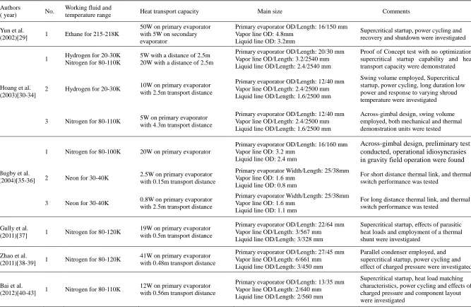
investigations were conducted, which are summarized in Table 1 and briefly reviewed below. .
Yun et al.[29] developed a CLHP and conducted the tests in a thermal-vacuum chamber for passive
optical bench cooling applications. Ethane was selected as the working fluid to provide an operating
temperature range of 215-218K. The outer diameter and length of the evaporator were 16 and 150mm,
respectively. All the transport lines were arranged in a serpentine style and plated with gold to minimize
parasitic heat losses. The experimental results clearly demonstrated the capability of type D CLHP, i.e. it
could start up reliably from a supercritical temperature of 335K to achieve a normal operating temperature
of 215K by using the secondary evaporator. With 5W applied to the secondary evaporator, the CLHP
achieved a 50W heat transport capability at 215K. A power cycle test was performed showing that the
system could adapt to rapid power changes. In addition, a heater located in the liquid line was required to
shut down the system in order to prevent the rapid decrease of the instrument temperature during the safe
mode, because simply turning power off to the primary and secondary evaporators cannot shut down the
Hoang et al.[30-34] first designed, fabricated and performance tested a proof-of-concept CLHP with
nitrogen and hydrogen as the working fluids in the initial research phase. Test results indicated that the
CLHP was capable of realizing supercritical startup and operating reliably, and the heat transport capability
could reach 50W×m (i.e. 20W over a distance of 2.5m) and 12.5W×m (i.e. 5W over a distance of 2.5m) for
nitrogen and hydrogen as the working fluids respectively with 1/8”OD vapor line and 3/32” OD liquid line.
In the following, hydrogen-charged and across-gimbal nitrogen-charged CLHPs with weight/volume design
optimization were developed and experimentally investigated. The optimized hydrogen-charged CLHP was
able to start up from an initially supercritical condition and operate in a very “hot” environment of 235K.
The cryocooling transport limit was 25W×m in 80K shroud and 22.5W×m in 235K. Throughout the test, it
demonstrated a robust/reliable operation and resilience in all aspects of operation such as severe power
cycling, low power long-duration runs, and it did not fail unexpectedly or exhibit noticeable anomalies. The
optimized across-gimbal nitrogen-charged CLHP was experimentally investigated by both the mechanical
demonstration unit and thermal demonstration unit, and Fig.9 shows the detailed structure of the
across-gimbal nitrogen-charged CLHP. In the mechanical demonstration unit, the motor controller and
peripheral electronics were programmed to autonomously rotate both azimuth and elevation coils in a
prescribed manner. A strange phenomenon was found that the 1/16”OD lines (being more flexible) lasted
even shorter than the 3/32” OD line perhaps due to a stress concentration on the 1/16”OD lines. In the
thermal demonstration unit, the experimental results show that the CLHP can realize the supercritical
startup successfully in less than 90 minutes with 5W applied to the secondary evaporator and 298K
surrounding; the heat transport capacity can reach 5W over a transport distance of 4.3meters; the CLHP can
operate with a small heat load applied to the primary evaporator for a long duration as long as the parasitic
well with the changes of heat loads applied to the primary evaporator.
Bugby et al.[35, 36] developed three CLHPs for solving important problems in cryogenic integration.
The three devices are an across-gimbal CLHP, a short transport length miniaturized CLHP and a long
transport length miniaturized CLHP. The across-gimbal CLHP was designed with nitrogen as the working
fluid with a heat transport range of 2-20W, and the coils should sustain at least 500 thousand cycles. Both
the short and long transport length CLHPs utilized neon as the working fluid and operated at the
temperature range of 30-40K, and Fig.10 shows the detailed structure of the short transport length
neon-charged CLHP. Preliminary test results show that the short transport length CLHP is able to transport
a heat load of 0.1-2.5W applied to the primary evaporator. The "ON" and "OFF" conductance is about 1
and 1400W/K respectively. While the long transport length CLHP is able to transport a heat load of 0.1-0.8
W applied to the primary evaporator. The "ON" conductance is about 0.7 W/K, and the "OFF" resistance is
estimated to be over 5000 K/W.
Gully et al.[37] developed a nitrogen-charged CLHP, and the general design, the instrumentation and the
experimental results of the thermal response of the CLHP were presented, analyzed and discussed both in
the transient phase of cooling from room temperature (i) and in stationary conditions (ii). During phase (i),
even in a severe radiation environment, the secondary loop helped to condense the fluid and was very
efficient to chill the primary evaporator. During phase (ii), the effects of transferred power, filling pressure
and radiation heat load for two basic configurations of cold reservoir of the secondary loop were studied. A
maximum heat load of 19W with a corresponding limited temperature difference of 5K was achieved
across a 0.5m distance. A small heating power (0.1W) applied to the shunted cold reservoir allowed to
maintain a constant subcooling (1K). The CLHP behaved as a capillary pumped loop (CPL) in such a
heat loads may affect significantly the thermal response of the system due to boiling process of liquid and
large mass transfer towards the gas reservoir.
Zhao et al.[38, 39] designed and experimentally investigated a nitrogen-charged CLHP with parallel
condenser structure. Experimental results confirmed that the CLHP could operate reliably with a high heat
transport capacity up to 41W and a limited temperature difference of 6K across a 0.48m transport distance,
and the supercritical startup and power cycling characteristics were also investigated. The possible fluid
inventory range of the CLHP was calculated based on the analysis of phase distribution of vapor and liquid
within the loop in a normal operation mode. Furthermore, a series of experiments were carried out with
various filling pressures of the gaseous nitrogen at room temperature for validation of the fluid inventory
range and identification of the optimal fluid inventory. The experimental results were compared with the
calculation results, and the effect of different charged pressure on the performance of the CLHP was
analyzed.
Bai et al.[40-43] developed a miniature nitrogen-charged CLHP as shown in Fig.11, and the principle
and method to determine the charged pressure of the working fluid was presented in detail. The unique
cylindrical condenser design could provide the interface with the cold finger of the cryocooler, and its
operating characteristics were experimentally investigated. Based on the experimental results, important
conclusions have been drawn: 1) with only 2.5W applied to the secondary evaporator, the CLHP can
realize the supercritical startup, and the larger the heat load applied to the secondary evaporator, the sooner
the temperature drop process of the primary evaporator; 2) when the heat load applied to the primary
evaporator is no less than 3W, the primary evaporator can operate independently; whereas when it is
smaller than 3W, the secondary evaporator must be kept in operation to assist the normal operation of the
decreases with the increase of the heat load applied to the primary evaporator; 4) the CLHP has the ability
to operate with a small heat load applied to the primary evaporator for a long time, and manifests good
thermal control performance. In addition, the effects of component layout including the connection points
of the gas reservoir to the working loop and the secondary loop line to the primary CC on the performance
characteristics of the CLHP have been studied.
As a research focus and for comparison purpose, Table 1 presents a summary of the development and
experimental results of CLHPs with type D including working fluids and operating temperature range, heat
transport capacity, main size and some comments on the design and characteristics.
3.4.4 Modeling development
So far, quite a few modeling and theoretical studies have been carried out on ALHPs including the
steady-state and transient performance as well as the startup characteristics [44-57]. Compared with ALHPs,
the modeling and theoretical investigation on the operating characteristics of CLHPs is quite limited and
obviously inadequate, and further study is still needed.
In Ref.[58], a steady-state mathematical model of a nitrogen-charged CLHP was established based on the
conservations of mass, momentum and energy of each component, and the modeling results including the
heat transport capacity and operating temperature variation trend showed good agreement with the
experimental data. Based on the mathematical model, parametric analysis including the effects of heat sink
temperature, parasitic heat load from the ambient, adverse elevation and heat load applied to the secondary
evaporator on the operating temperature of the CLHP was conducted, and several important conclusions
have been drawn. In Ref.[59], the mathematical model of the supercritical startup of a nitrogen-charged
CLHP was established based on the nodal network method, and the supercritical startup process was
cooling of the secondary evaporator; stage 2 is the cooling of the primary evaporator and stage 3 is the
startup of the main loop. Note that, the cooling of the secondary evaporator is the prerequisite to startup the
auxiliary loop, and the startup of the auxiliary loop can realize the cooling and liquid saturation of the
primary evaporator, which is the prerequisite to startup the main loop. Key factors affecting the
supercritical startup performance was analyzed, and conclusions below have been drawn: a higher working
fluid charged pressure and an enhanced thermal conductance between the secondary CC and heat sink can
both shorten the time needed to complete the cooling of the secondary evaporator; a smaller parasitic heat
load from the ambient and a larger heat load applied to the secondary evaporator can both shorten the time
needed to complete the cooling of the primary evaporator; when the parasitic heat load is relatively large, it
is possible that the primary evaporator wick can never be saturated with liquid, and the supercritical startup
of CLHPs will fail; a larger parasitic heat load from the ambient can result in a higher steady-state
operating temperature of the primary evaporator; a larger startup heat load can shorten the time needed to
complete the startup of the main loop.
3.4.5 Design optimization
In order to put CLHPs into space applications, it is necessary to reduce its weight/volume considerably
enhance its heat transport capacity and manage the parasitic heat load effectively, and design optimization
plays an important role to reach such a goal.
Generally, the gas reservoir is disproportionally larger than any other component of the CLHP, i.e. its
volume is several tens times larger than the working loop volume, so any weight/volume reduction scheme
must focus on the gas reservoir. As the gas reservoir volume is proportional to the amount of liquid in the
system needed for normal operation, an obvious solution to the weight/volume problem is to minimize the
startup even without a gas reservoir is to condense as much liquid as required to realize the startup of the
secondary evaporator. Based on the two schemes mentioned above, Hoang et al.[60] conducted an
optimization design on a hydrogen-charged CLHP by the miniaturization of loop components especially the
liquid-filled components such as the primary and secondary evaporators, condensers and liquid transport
lines and incorporation of a swing volume at the inlet of the primary condenser. Results of analyses
indicated that a 10-fold decrease of the gas reservoir volume was possible providing that high performance
wicks with pore size of <1.5micron were employed in both the primary and secondary evaporators.
To enhance the heat transport capacity, Zhao et al.[38] designed and experimentally investigated a
nitrogen-charged CLHP with improved condenser structure. The improved condenser of the CLHP was
made of a cubic copper block with machined parallel pipes inside. The flow resistance of the working fluid
in this improved condenser structure is reduced considerably. Furthermore, the heat transfer performance
between the condenser and the heat sink could be improved effectively compared with conventional
condenser design by the elimination of additional thermal contact resistance. Experimental results
confirmed that the heat transport capacity of the CLHP could be enhanced up to 41W across a 0.48m
transport distance.
To manage the parasitic heat load from the ambient, several designs have been proposed including the
employment of transport lines with gold-plated exterior surface and miniaturized OD and the coaxial
design of the primary liquid line and the secondary loop line. The employment of transport lines with
gold-plated exterior surface and miniaturized OD can effectively reduce the parasitic heat load by
decreasing the heat transfer area and absorption rate of the transport lines simultaneously. For the coaxial
design, the primary liquid line is coaxially within the secondary loop line, and the parasitic heat load on the
good choice.
3.5 Type E
3.5.1 System structure
To enable cryocooling of a heat source with a large area, the CLHP with type E has been developed, and
Fig.12 shows the schematic of this type of CLHP. As shown in Fig.9, the CLHP is composed of an
evaporator, a condenser, a capillary pump, a CC and transport lines plus a gas reservoir. The capillary pump
and CC are attached directly to the heat sink. A notable change in this design is that the capillary pump is
utilized not to acquire heat directly from the heat sources but simply to generate fluid flow in the loop. An
electrical heater, bonded to the capillary pump body, provides necessary heat input for operation.
Meanwhile, the evaporator is just composed of flexible small-diameter smooth-walled pipelines with no
wicks inside, which has very good adaptability to heat sources with large area and complex structure.
3.5.2 Supercritical startup
For the CLHP with type E to realize the supercritical startup, the capillary pump method has been
proposed. The capillary pump method is to utilize the capillary pump as an assistant to realize the cooling
and liquid accumulation of the evaporator of the CLHP. For a CLHP adopting the capillary pump method,
the supercritical startup process is as follows: prior to startup, the whole CLHP is initially at the ambient
state; as the cryogenic heat sink takes effect, the temperature of the capillary pump and CC begins to drop
quickly as well as the condenser, and fluid condensation will occur when it drops to the saturation
temperature with respect to local pressure; with continuous condensation of working fluid in the CC, the
capillary pump wick will be fully saturated with liquid, under this situation, heat load from an electrical
heater can be applied to the capillary pump to make it start; once the capillary pump is started, the vapor
transport lines, which could realize the temperature drop and subsequent liquid accumulation in the
evaporator; with continuous liquid accumulation in the evaporator, heat load from the heat source can be
applied to the evaporator to complete the supercritical startup of the CLHP.
3.5.3 Experimental results
Hoang et al. [61, 62] designed and experimentally investigated CLHPs with neon and helium as the
working fluids respectively. Fig.13 shows the test unit of the Ne-CLHP, where the outer diameter and
length of the capillary pump wick were 5.3 and 50.8mm respectively. In the Ne-CLHP experiments, the
pump heater was activated with 1W to start fluid circulation in the loop. It cooled down the evaporator
plate effortlessly from a supercritical condition (100K) with a rate of 30-40K per hour, and no special wick
priming procedure was required. The maximum cooling capacity was 4.2W over an evaporator area of
48in2 with 2.5W applied to the capillary pump. Temperature control of the evaporator under loads was
easily accomplished by simply regulating the power input to the capillary pump. Increasing the capillary
pump heater power lowered the evaporator temperature, and conversely, decreasing the pump heater power
raised the evaporator temperature. Low power operation was also demonstrated with 1W on the evaporator
and 0.5W on the capillary pump. Effects of fluid charge level on the Ne-CLHP operation were also
investigated: overcharging the test loop would result in partial liquid blockage of both reservoir and
condenser, making the heat transfer between the condenser and cryocooler less effective. In order to
dissipate the same amount of heat, the condenser-to-cryocooler temperature difference had to increase.
With the exception of higher saturation temperatures for overcharging, no other performance difference
was detected including the capillary pump power limit and the evaporator cooling capacity.
He-CLHP was the first-ever operational capillary cryocooling transport in the 3-5K temperature range.
extremely accurate. In the He-CLHP experiments, a Helium dewar was employed to act as the heat sink at
~2.5-2.7K. In the supercritical startup, when the loop temperatures dropped below 2.7K, 10mW was
applied to the capillary pump to start the fluid circulation in the loop, about 8mins later, 15mW was applied
to the evaporator to begin the operation, and the He-CLHP finally reached steady state with the saturation
temperature leveling off just below 2.8K. The power cycling characteristics of the He-CLHP was
investigated. With the pump power kept at 50mW, the evaporator power was stepped up to 60mW from
50mW, the loop temperatures changed very little, but the evaporator temperature increased by 0.25K. The
evaporator power was subsequently stepped up with a 10mW increment until it reached the anticipated
limit of 100mW. Again the loop temperatures changed little (went up from 3.5K to 3.7K) but the
evaporator temperature went up ~0.7K for every 10mW power step-up. In another test, the evaporator was
kept at 50mW while the pump power was reduced slowly from 35mW. As the pump power decreased, the
evaporator temperature increased as expected. When it got to 25mW, the evaporator temperature was able
to level off at 5K.
4 Comparative analyses
4.1 System structure
Generally, a gas reservoir with a relatively large volume is an indispensable component of all types of
CLHPs. This is due to the fact that a CLHP operate at very low temperature range, the working fluid in
the loop is in the two-phase state and its pressure seldom exceeds several atmospheres when it is in
operation. However when it is idle and the whole system is at ambient temperature, far higher than the
critical temperature of the cryogenic working fluid. The working fluid is in the supercritical state. As the
liquid of the cryogenic working fluid under the same pressure, the pressure in the loop would reach several
hundred atmospheres or even higher. Without the employment of a gas reservoir, a much higher demand of
structural robustness and sealing is required for CLHPs as well as the storage security. The idle pressure of
the CLHP can be reduced considerably by employing a gas reservoir with a relatively large volume. The
reduction of idle pressure also mitigated the difficulties of startup of a CLHP, as discussed in detail below.
In addition to the gas reservoir, additional components are required to assist the smooth startup and
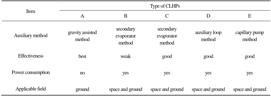
operation of a CLHP, as summarized in Table 2 From the structure consideration, Type A CLHP is
based on the gravity assisted method, and has the simplest structure; while the CLHP with type D
adopting the auxiliary loop method has the most complex structure. It is of note that the CLHPs with
types A-D are suitable to concentrated heat sources but type E is only applicable to heat sources with
large areas.
4.2 Supercritical startup
The startup capability is one of the key aspects to evaluate the LHP performance, and is also the first
issue to be resolved to for any practical applications. For an ALHP, the working fluid inside is in the
two-phase state at the ambient state, and the evaporator wick can be always saturated with liquid through
proper of the CC volume and working fluid inventory. Under such a situation, heat load can be directly
applied to the evaporator to start up the ALHP. However, the startup process of a CLHP is more
complicated than that of an ALHP as the fluid is at the supercritical state . The evaporator wick must be
cooled down and saturated with liquid prior to the application of a heat load.
In order to realize the supercritical startup, several methods have been proposed including the gravity
assisted method, the secondary evaporator method, the auxiliary loop method and the capillary pump
different types. As shown in Table 3, the gravity-assisted method is proven to be very effective in achieving
the supercritical startup without additional power consumption. However as it depends on the gravity
as an assistant, it is not suitable for space applications. Type B and C CLHPs both adopt the secondary
evaporator method but with different structures. Type B is difficult to establish one way circulation of the
working fluid in the loop due to its location. The length and diameter of the vapor and liquid transport lines
should be designed properly to minimize the flow resistance in order to provide effective cooling and liquid
saturation of the primary evaporator wick. It is expected that the transport distance of the CLHP is short. .
However for type C, one way circulation of working fluid in the loop can be effectively established,
which provided better cooling and liquid saturation of the primary evaporator wick. The auxiliary loop
method and the capillary pump method are both very effective to help realize the supercritical startup of
CLHPs, but with added complexities in the loop.
4.3 Heat transport capacity
The heat transport capacity of a CLHP is decided not only by the fluid properties but also the system
structure. Section 2 shows that cryogenic fluids possess much lower Dunbar Parameter, implying a
smaller heat transport capacity than that of ALHPs. The additional components of a CLHP and their
arrangement to assist smooth startup would bring additional flow resistance that affect its heat transport
capability. Type A CLHP has good heat transfer capability due to the gravity assistance measure and no
additional components added in the main loop. For type B, although a secondary evaporator is added in
series inside the condenser, the simple design of the secondary evaporator (i.e. a pipe with axial grooves
machined on its inner surface) would not cause large flow resistance. The introduce of the secondary
evaporator would not affect the heat transport capacity of the CLHP significantly . For type C, the working
increased the flow resistance , resulting in a decreased heat transport capacity. For type D, when the
secondary evaporator is not in operation, it does not bring additional flow resistance as the auxiliary loop is
in parallel with the main loop , and the heat transport capacity is not affected. When the secondary
evaporator is in operation, however, it will lead to an increased mass flowrate in the primary condenser and
primary liquid line. The increased pressure drop would reduce the heat transport capacity of the CLHP
Type E has a fixed distance between the heat source and heat sink, the working fluid has to travel back
and forth between the heat source and heat sink several times. The increase in the total travel distance of
the working fluid increase the total pressure drop of working fluid circulating along the loop and would
decrease the heat transport capacity of the CLHP considerably.
4.4 Effect of parasitic heat load
The parasitic heat load is the heat absorbed from the ambient by LHPs when the temperatures of the
entire LHP or some components are lower than the ambient temperature. For an ALHP, the parasitic heat
needs to be considered when the operating temperature is lower than the ambient temperature or the heat
sink temperature is lower than the ambient temperature. When the heat load applied to the evaporator is
small, the intake of the parasitic heat load would increase the operation temperature significantly. and
decrease the system conductance. The existence of the variable conductance mode in ALHPs operation is
mainly due to the parasite heat. The problem of parasite heat is mitigated at higher heat loads. The
increased mass flowrate of the working fluid in the loop would inhibit the effect of parasitic heat load.
Generally speaking, the parasitic heat load is not a big issue during the normal operation of an ALHP as
the temperature difference between the LHP components and the ambient is usually very small. . In some
operating temperature of ALHPs within the required range when the heat load applied to the evaporator is
subjected to a large range of variation. Most of the parasite heat can be managed effectively through
proper insulation..
Different from the ALHP, the issue of parasitic heat load for CLHP becomes severe, and it may even
stop its normal operation . That is due to two main reasons: i) the temperature difference between the CLHP
components and the ambient is rather large, which would produce high parasite heat, and ii) the heat
transport capability is much smaller for a CLHP, and the negative effect of parasitic heat load on the
CLHPs operation becomes more obvious especially for the antigravity operation. Under an anti-gravity
operation, the temperature of the return liquid would rise continually as it flows along the liquid
transport line due to the parasite heat intake and at the same time, its pressure drops constantly due to the
gravity effect. The return liquid may reach a saturated state and begin to boil. In a more server case, the
temperature of the return liquid may exceed its critical temperature and become supercritical at the outlet of
the liquid transport line. Under these situations , the CLHP cannot operate normally due to the failure in
liquid replenishment to the evaporator wick.
To ensure successful supercritical startup and normal operation of CLHPs, strict insulation measures
must be employed to reduce the parasitic heat load In most ground experiments, CLHPs are generally
placed in a thermal-vacuum chamber, and all the CLHP components except the gas reservoir are protected
by multi-layer insulation materials. In some situations, a low temperature shield between the CLHP and
the inner wall of the thermal-vacuum chamber may be utilized, which effectively create a cold
environment for CLHPs and minimize the adverse effect of parasitic heat load.
It is of note that Type D CLHP has the ability to manage the problem of parasitic heat load,
loop is in parallel with the main loop. When the primary evaporator is in normal operation, the secondary
evaporator can be kept in operation simultaneously, which can increase the mass flowrate of the working
fluid and inhibit the temperature rise due to parasite heat. The increase in the subcooling of the returning
liquid is crucial for the stable operation of the primary evaporator for Type D CLHP, especially under low
heat loads. .
4.5 Design optimization
There are still many scope to improve the performance of LHPs. For ALHPs, most recent studies focus
on the performance improvement of the evaporator wick, and quite a few researchers have developed and
investigated the biporous or bidisperse wicks to enable the evaporator with high capillary pumping
capability, and low flow resistance yet with excellent evaporative heat transfer performance[63-67].
Clearly similar or improved wick structure could be applied to CLHPs. In addition, an optimized
consideration of the weight/volume reduction, enhancement in heat transport capacity and management of
the parasitic heat load is essential to achieve better performance. Some of these requirements may be
contradictory sometimes. For instance the employment of small diameter transport lines can reduce the
system weight/volume and the parasitic heat load from the ambient, but it also decrease the heat transport
capacity of the CLHP. Clearly much progress has been made on the design optimization of CLHPs, further
comprehensive and in-depth research is still needed to progress the application of CLHPs into space in
the near future.
5 Conclusions
categorized into five types mainly based on the system structural characteristics. A comparative study both
between CLHPs and ALHPs and among different types of CLHPs has been conducted covering a variety of
aspects including the working fluid, system structure, supercritical startup, heat transport capacity, effect of
parasitic heat load as well as the design optimization, in order to clarify the principal differences in the
performance characteristics and application fields for CLHPs with different types. This work contributes to
a better understanding of the development and operating principle and characteristics of CLHPs, and can
guide the design and application of these devices.
ACKNOWLEDGEMENTS
This work was supported by Beijing Natural Science Foundation (No. 3144031), the National Natural
Science Foundation of China (No. 51306009) and the EU Marie Curie Actions-International Incoming
References
[1] Y.F. Maydanik, Loop heat pipes, Applied Thermal Engineering 25(2005) 635-657
[2] J. Ku, Operating characteristics of loop heat pipes, SAE paper, No.1999-01-2007,1999
[3] G.H. Wang, D. Mishkinis, D. Nikanpour, Capillary heat loop technology: space applications and recent
Canadian activities, Applied Thermal Engineering 28(2008) 284-303
[4] F. Bodendieck, B. Hollenbach, K. Goncharov, Propylene LHP for the AMS Cryo-Cooler Thermal
Control System, AMS 02 Technical Note, Document No. AMS-OHB-TEN-003, 2005
[5] V. Perotto, S. Tavera, K. Goncharov, Development of improved 1500W Deployable Radiator with
Loop Heat Pipe, SAE paper, No.2000-01-2458, 2000
[6] M.L. Parker, Modeling of loop heat pipe with applications to spacecraft thermal control, Pennsylvania:
Faculty of Mechanical Engineering and Applied Mechanics, University of Pennsylvania , 2000
[7] Eric W. Grob, Mission performance of the GLAS thermal control system-7 years in orbit, AIAA Paper,
No.2010-6029, 2010
[8] Jose I. Rodriguez, Arthur Na-Nakornpanom, In-flight performance of the test loop heat pipe heat
rejection system-seven years in space, AIAA Paper, No. 2012-3500, 2012
[9] N. Wang, Z. Cui, J. Burger, et al., Transient behaviors of loop heat pipes for alpha magnetic
spectrometer cryocoolers, Applied Thermal Engineering 68 (2014) 1-9
[10] J. Xu, X. Ji, W. Yang, et al., Modulated porous wick evaporator for loop heat pipes: Experiment,
International Journal of Heat and Mass Transfer 72 (2014) 163-176
[11] J. Li, D. Wang, G.P. Peterson, Experimental Studies on a High Performance Compact Loop Heat Pipe
with Flat Square Evaporator for High Power Chip Cooling, Applied Thermal Engineering 30(2010)
[12] M. Mitomi, H. Nagano, Long-distance loop heat pipe for effective utilization of energy, International
Journal of Heat and Mass Transfer 77 (2014) 777-784
[13] A.L. Phillips, K.L. Wert, Loop Heat Pipe Anti Icing System Development Program Summary, SAE
Paper, No. 2000-01-2493, 2000
[14] L. Bai, G. Lin, D. Wen, et al. Experimental investigation of startup behaviors of a dual compensation
chamber loop heat pipe with insufficient fluid inventory, Applied Thermal Engineering 29 (2009)
1447-1456
[15] J. Feng, G. Lin, L. Bai, Experimental investigation on operating instability of a dual compensation
chamber loop heat pipe, Science in China Series E: Technological Sciences 52(2009) 2316-2322
[16] G. Lin, N. Li, L. Bai, et al. Experimental investigation of a dual compensation chamber loop heat pipe,
International Journal of Heat and Mass Transfer 53(2010) 3231-3240
[17] Y.F. Maydanik, S. Vershinin, M. Chernysheva, et al. Investigation of a compact copper-water loop
heap pipe with a flat evaporator, Applied Thermal Engineering 31(2011) 3533-3541
[18] V.G. Pastukhov, Y.F. Maydanik, C.V. Vershinin, et al. Miniature Loop Heat Pipes for electronics
cooling, Applied Thermal Engineering 23(2003) 1125-1135
[19] Y.F. Maydanik, V.V. Sergey, G. Pastukhov, et al., Loop Heat Pipes for Cooling Systems of Servers,
IEEE TRANSACTIONS ON COMPONENTS AND PACKAGING TECHNOLOGIES 33(2)( 2010)
416-423
[20] V.G. Pastukhov, Y.F. Maydanik, Low-noise cooling system for PC on the base of Loop Heat Pipes,
Applied Thermal Engineering 27(2007) 894-901
[21] Y.F. Maydanik, M.A. Chernysheva, V.G. Pastukhov, Review: Loop heat pipes with flat evaporators,
[22] H. Pereira, F. Haug, P. Silva, et al., Cryogenic loop heat pipes for the cooling of small particle
detectors at CERN, Advances in Cryogenic Engineering: Transactions of the Cryogenic Engineering
Conference 55(2010) 1039-1046
[23] Q. Mo, J. Liang, A novel design and experimental study of a cryogenic loop heat pipe with high heat
transfer capability, International Journal of Heat and Mass Transfer 49(2006) 770-776
[24] Q. Mo, J. Liang, J. Cai, Investigation of the effects of three key parameters on the heat transfer
capability of a CLHP, Cryogenics 47(2007) 262-266
[25] Q. Mo, J. Liang, Operational performance of a cryogenic loop heat pipe with insufficient working
fluid inventory, International Journal of Refrigeration 29(2006) 519-527
[26] D. Khrustalev, S. Semenov, Advances in Low-Temperature, Cryogenic, and Miniature Loop Heat
Pipes, Presentation at the 12thAnnual Spacecraft Thermal Control Technology Workshop, El Segundo,
March 2003
[27] D. Khrustalev, Cryogenic Loop Heat Pipes as Flexible Thermal Links for Cryocoolers, Proc. of the
12th Int. Cryocooler Conference, June 18-20, 2002, Cambridge, MA, USA, 709-716
[28] D. Khrustalev, Test Data for a Cryogenic Loop Heat Pipe Operating in the Temperature Range from
65k to 140K, Presentation at the International Two-Phase Thermal Control Technology Workshop,
Mitcheville, MD, September 24-26, 2002
[29] J. Yun E. Kroliczek L. Crawford, Development of a Cryogenic Loop Heat Pipe (CLHP) for Passive
Optical Bench Cooling Applications, SAE paper, No. 2002-01-2507
[30] T.T. Hoang, T.A. O’Connell, D.K. Khrustalev, Development of a Flexible Advanced Loop Heat Pipe
for Across-Gimbal Cryocooling, Proceedings of SPIE Vol. 5172 (2003) 68-76
Temperature Range of 20-30K, 12th International Heat Pipe Conference, Moscow, 2002
[32] T.T. Hoang, T.A. O’Connell, J. Ku, Management of Parasitics in Cryogenic Advanced Loop Heat
Pipes, AIAA paper, No.2003-0346, 2003
[33] T.T. Hoang, T.A. O’Connell, Performance demonstration of flexible advanced loop heat pipe for
across-gimbal cryocooling, AIAA paper, No. 2005-5590, 2005
[34] T.T. Hoang, T.A. O’Connell, J. Ku, et al., Performance Demonstration of a Hydrogen Advanced Loop
Heat Pipe for 20-30K Cryocooling of Far Infrared Sensors, Proceedings of SPIE, Vol.5904, 2005
[35] D. Bugby, B. Marland, C. Stouffer, et al., Across-gimbal and miniaturized cryogenic loop heat pipes,
Space technology and applications international forum-STAIF (2003) 218-226
[36] D. Bugby, B. Marland, C. Stouffer, et al., Development of advanced tools for cryogenic integration,
Advances in Cryogenic Engineering: Transactions of the Cryogenic Engineering Conference 49(2004)
1914-1922
[37] P. Gully, Q. Mo, T. Yan, et al., Thermal behavior of a cryogenic loop heat pipe for space application,
Cryogenics 51 (2011) 420-428
[38] Y. Zhao, T. Yan, J. Liang, Experimental study on a cryogenic loop heat pipe with high heat capacity,
International Journal of Heat and Mass Transfer 54(2011) 3304-3308
[39] T. Yan, Y. Zhao, J. Liang, et al., Investigation on optimal working fluid inventory of a cryogenic loop
heat pipe, International Journal of Heat and Mass Transfer 66 (2013) 334-337
[40] L. Bai, G. Lin, H. Zhang, et al. Experimental study of a nitrogen-charged cryogenic loop heat pipe,
Cryogenics, 52 (2012) 557-563
[41] L. Bai, G. Lin, H. Zhang, et al. Operating characteristics of a miniature cryogenic loop heat pipe,
International Journal of Heat and Mass Transfer, 55 (2012) 8093-8099
[42] L. Bai, G. Lin, H. Zhang, et al. Effect of component layout on the operation of a miniature cryogenic
[43] C. Du, L. Bai, G. Lin, et al., Determination of charged pressure of working fluid and its effect on the
operation of a miniature CLHP, International Journal of Heat and Mass Transfer 63(2013) 454-462
[44] M.A. Chernysheva, S.V. Vershinin, Y.F. Maydanik, Operating temperature and distribution of a
working fluid in LHP, International Journal of Heat and Mass Transfer 50 (2007) 2704-2713
[45] L. Bai, G. Lin, H. Zhang, et al. Mathematical modeling of steady state operation of a loop heat pipe,
Applied Thermal Engineering, 29 (2009), 2643-2654
[46] V.V. Vlassov, R.R. Riehl, Mathematical model of a loop heat pipe with cylindrical evaporator and
integrated reservoir, Applied Thermal Engineering, 28(2008), 942-954
[47] T.T. Hoang, T.A. O’Connell, J. Ku, Mathematical modeling of loop heat pipes with multiple capillary
pumps and multiple condensers, Part I – steady state simulations, AIAA paper, No.2004-5577, 2004
[48] T. Kaya, T.T. Hoang, J. Ku, Mathematical Modeling of Loop Heat Pipes, AIAA paper, No. 99-0477,
1999
[49] T.T. Hoang, T. Kaya, Mathematical Modeling of Loop Heat Pipes with Two-phase Pressure Drop,
AIAA paper, No. 99-3448, 1999
[50] J. Ambrose, E. Buchan, B. Yendler, Modeling and Test Results for a Loop Heat Pipe with
Parallel-Flow Condenser, AIAA paper, No. 2000-2280, 2000
[51] S. Launay, V. Sartre, J. Bonjour, Parametric analysis of loop heat pipe operation: a literature review,
International Journal of Thermal Science, 46 (2007) 621-636
[52] L. Bai, G. Lin, D. Wen, Modeling and analysis of startup of a loop heat pipe, Applied Thermal
Engineering 30 (2010) 2778-2787
[53] M.A. Chernysheva, V.G. Pastukhov, Y.F. Maydanik, Analysis of heat exchange in the compensation
[54] B. Siedel, V. Sartre, F. Lefèvre, Numerical investigation of the thermohydraulic behaviour of a
complete loop heat pipe, Applied Thermal Engineering 61 (2013) 541-553
[55] J. Li, G.P. Peterson, 3D heat transfer analysis in a loop heat pipe evaporator with a fully saturated
wick, International Journal of Heat and Mass Transfer 54(2011) 564-574
[56] M.A. Chernysheva, Y.F. Maydanik, 3D model for heat and mass transfer simulation in flat evaporator
of copper-water loop heat pipe, Applied Thermal Engineering 33-34(2012) 124-134
[57] M.A. Chernysheva, Y.F. Maydanik, Simulation of thermal processes in a flat evaporator of a
copper-water loop heat pipe under uniform and concentrated heating, International Journal of Heat and
Mass Transfer 55(2012) 7385-7397
[58] L. Bai, G. Lin, D. Wen, Parametric analysis of steady-state operation of a CLHP, Applied Thermal
Engineering 30(2010) 850-858
[59] L. Bai, G. Lin, D. Wen, Modeling and analysis of supercritical startup of a cryogenic loop heat pipe,
Journal of Heat Transfer-Transactions of ASME 133(2011) No.121501
[60] T.T. Hoang, T.A. O’Connell, J. Ku, et al., Design optimization of a hydrogen advanced loop heat pipe
for space-based IR sensor and detector cryocooling, Proceedings of SPIE 5172(2003) 86-96
[61] T.T. Hoang, T.A. O’Connell, J. Ku, et al., Large Area Cryocooling for Far Infrared Telescopes
Proceedings of SPIE Vol. 5172 (2003) 77-85
[62] T.T. Hoang, T.A. O’Connell, D.A. Suhkov, Large Area Cooling with Cryogenic Loop Heat Pipes,
AIAA paper, No. 2007-4272, 2007
[63] Z. Liu, H. Li, B. Chen, et al., Operational characteristics of flat type loop heat pipe with biporous wick,
58(2012) 180-185
[64] F. Lin, B. Liu, C. Huang, et al., Evaporative heat transfer model of a loop heat pipe with bidisperse
[65] F. Lin, B. Liu, C. Juan, et al., Effect of pore size distribution in bidisperse wick on heat transfer in a
loop heat pipe, Heat Mass Transfer 47 (2011) 933-940
[66] R. Singh, A. Akbarzadeh, M. Mochizuki, Effect of Wick Characteristics on the Thermal Performance
of the Miniature Loop Heat Pipe, Journal of Heat Transfer Vol. 131, paper No. 082601
[67] C. Yeh, C. Chen, Y.M. Chen, Heat transfer analysis of a loop heat pipe with biporous wicks,
Table captions
Table 1 Summary of CLHPs with type D
Table 2 Added components for CLHPs with different types compared to ALHPs
Figure captions
Fig.1 Detailed structure of the evaporator and CC
Fig.2 Schematic of a typical LHP
Fig.3 Variation of Dunbar Parameter of ammonia and water
Fig.4 Variation of Dunbar Parameter of cryogenic working fluids
Fig.5 Schematic of the CLHP with type A
Fig.6 Schematic of the CLHP with type B
Fig.7 Schematic of the CLHP with type C
Fig.8 Schematic of the CLHP with type D
Fig.9 Detailed structure of across-gimbal N2-CLHP[33]
Fig.10 Detailed structure of short transport length Ne-CLHP[35]
Fig.11 Detailed structure of N2-CLHP with cylindrical condenser[41]
Fig.12 Schematic of the CLHP with type E
Table 1 Summary of CLHPs with type D Authors
( year) No.
Working fluid and
temperature range Heat transport capacity Main size Comments Yun et al.
(2002)[29] 1 Ethane for 215-218K
50W on primary evaporator with 5W on secondary evaporator
Primary evaporator OD/Length: 16/150 mm Vapor line OD: 4.8mm
Liquid line OD: 3.2mm
Supercritical startup, power cycling and recovery and shutdown were investigated
Hoang et al. (2003)[30-34]
1 Hydrogen for 20-30K Nitrogen for 80-110K
5W with a distance of 2.5m 20W with a distance of 2.5m
Primary evaporator OD/Length: 20/30 mm Vapor line OD/Length: 3.2/2540 mm Liquid line OD/Length: 2.4/2540 mm
Proof of Concept test with no optimization, supercritical startup capability and heat transport capacity were demonstrated
2 Hydrogen for 20-30K 10W on primary evaporator with 2.5m transport distance
Primary evaporator OD/Length: 12/40 mm Vapor line OD/Length: 2.4/2500 mm Liquid line OD/Length: 1.6/2500 mm
Swing volume employed, Supercritical startup, power cycling, long duration low power and response to varying shroud temperature were investigated 3 Nitrogen for 80-110K 5W on primary evaporator
with 4.3m transport distance
Primary evaporator OD/Length: 12/40 mm Vapor line OD/Length: 2.4/2500 mm Liquid line OD/Length: 1.6/2500 mm
Across-gimbal design, swing volume employed, both mechanical and thermal demonstration units were tested
Bugby et al. (2004)[35-36]
1 Nitrogen for 80-100K 20W on primary evaporator
Primary evaporator OD/Length: 16/160 mm Vapor line OD: 3.2 mm
Liquid line OD: 2.4 mm
Across-gimbal design, preliminary test conducted, operational idiosyncrasies in gravity field operation were found
2 Neon for 30-40K 2.5W on primary evaporator with 0.15m transport distance
Primary evaporator Width/Length: 25/38mm Vapor line OD: 1.6 mm
Liquid line OD: 0.8 mm
For short distance thermal link, and thermal switch performance was tested
3 Neon for 30-40K 0.8W on primary evaporator with 2.5m transport distance
Primary evaporator Width/Length: 25/38mm Vapor line OD: 1.6 mm
Liquid line OD: 1.1 mm
For long distance thermal link, and thermal switch performance was tested
Gully et al.
(2011)[37] 1 Nitrogen for 80-120K
19W on primary evaporator with 0.5m transport distance
Primary evaporator OD/Length: 22/64 mm Vapor line OD/Length: 3/567 mm Liquid line OD/Length: 3/328 mm
Supercritical startup, effects of parasitic heat loads and employment of a thermal shunt were investigated
Zhao et al.
(2011)[38-39] 1 Nitrogen for 80-120K
41W on primary evaporator with 0.48m transport distance
Primary evaporator OD/Length: 27/45 mm Vapor line OD/Length: 6/661 mm Liquid line OD/Length: 3/450 mm
Parallel condenser employed, and supercritical startup, power cycling and effect of charged pressure were investigated Bai et al.
(2012)[40-43] 1 Nitrogen for 80-110K
12W on primary evaporator with 0.56m transport distance
Primary evaporator OD/Length: 13/35 mm Vapor line OD/Length: 2/640 mm Liquid line OD/Length: 2/560 mm
Table 2 Added components for CLHPs with different types compared to ALHPs Type Added components Structure complexity Heat source
A a gas reservoir most simple concentrated B a secondary evaporator and a gas reservoir simple concentrated C a secondary evaporator, a secondary CC, a
secondary condenser and a gas reservoir intermediate concentrated D
a secondary evaporator, a secondary CC, a secondary condenser, a secondary loop line and a gas reservoir
most complex concentrated E an evaporator composed of flexible pipelines
and a gas reservoir intermediate large area
Table 3 Comparison of supercritical startup for CLHPs with different types
Item
Type of CLHPs
A B C D E
Auxiliary method gravity assisted method secondary evaporator method secondary evaporator method auxiliary loop method capillary pump method Effectiveness best weak good good good Power consumption no yes yes yes yes
[image:37.595.68.533.394.559.2]Fig.1 Detailed structure of the evaporator and CC
Heat input
Heat output
Evaporator
Liquid line
Condenser
Vapor line CC
Vapor groove Wick
liquid vapor wick
Fig.2 Schematic of a typical LHP
Vapor groove
Evaporator core
Bayonet
Wick Compensation Chamber
Fig.3 Variation of Dunbar Parameter of ammonia and water
(a) Nitrogen, argon and oxygen (b) Hydrogen and helium
CC
Condenser Evaporator
Gas reservoir
Heat sink Vapor line
Liquid line
Fig.5 Schematic of the CLHP with type A
CC
Condenser Primary
evaporator
Gas reservoir
Heat sink Vapor line
Liquid line
Secondary evaporator
Primary CC
Primary condenser
Primary evaporator
Gas reservoir Heat sink
Vapor line
Liquid line
Secondary condenser Secondary evaporator
Secondary CC
Fig.7 Schematic of the CLHP with type C
Primary CC
Primary condenser Primary evaporator
Gas reservoir
Heat sink Primary vapor line
Primary liquid line
Secondary condenser Secondary CC
Secondary evaporator
Secondary loop line
Fig.9 Detailed structure of across-gimbal N2-CLHP[33]