1
Computational techniques for simulation of damage and failure on
composites
J.L. Curiel-Sosaa, R. Brighentib, M.C. Serna Morenoc , E. Barbierid
a Department of Mechanical Engineering, University of Sheffield Sir Frederik Mappin Building, Sheffield S1 3JD, UK b Department of Civil-Environmental Engineering & Architecture, University of Parma.
Viale delle Scienze, 181/A -43124 Parma, Italy
c Mecánica de los Medios Continuos y Teoría de Estructuras, E.T.S.I. Industriales. Edificio Politécnico
Avda. Camilo José Cela, s/n Campus Universitario. 13071 Ciudad Real , Spain
d School of Engineering and Materials Science, Queen Mary University of London
Mile End Road, E1 4NS London, UK
Abstract
This chapter presents some of the most recent and relevant computational techniques for modelling and simulation of damage and/or failure on composite materials. In the last few years, the number of computer methods dedicated to virtual composite damage simulation has exploded as a consequence of progress on a number of numerical methods such as the Partition of Unity Methods (Extended Finite Element Method, Phantom Node Method,...), meshfree methods (Particle Methods, Element Free Galerkin Method,..) or semi-numerical approaches linking novel strategies for computation of damage based on phenomenological theories and effective replication of cracks embedded within the Finite Element Method. Although, this chapter deals mainly with computer methods applied to fibre reinforced composites based on a polymeric matrix, many of them are applicable to a broader range of composite materials as well as other anisotropic materials.
Contents
1 Introduction ………..2
2 Semi-numerical Techniques ………4
2.1 Progressive Damage Models within FEM ………..4
2.2 Interface/cohesive elements for the progressive degradation of laminates …….. ..8
3 Meshless Methods ……….9
3.1 Peridynamics………..……….10
3.2 Element Free Galerkin………...………….10
4 Partition of Unity Methods ………10
4.1 The eXtended Finite Element Method (XFEM) ………..………..11
4.2 Phantom Node Method (PNM) ……….……….12
5 Multiscale and Homogenisation ………12
5.1 Energy-based homogenisation approach for short fibre-reinforced materials.…..14
Nomenclature
j
a , bk FE additional degrees of freedom for the displacement
approximation
2
C fourth–order damaged stiffness tensor
h
'
C , C'm Composite homogenized and matrix tangent stiffness
tensor, respectively
j
c threshold for the strain damage surface j
0
C ‘Virgin’ stiffness matrix
i
E Young modulus of the fiber-matrix interface
ic
G Fracture energy of the fiber-matrix interface
D damage tensor
ic
K Fibre-matrix interface fracture toughness
) (x
H Heaviside function
j i N
N , FE shape functions
F η
σ , ),
( n n
f Stress damage surface and corresponding tensor
G Strain damage tensor
j
j G c
c
g(εε, ): (εε) undamaged elastic domain in the strain space
) ( ), (
p
p Probability distribution functions of the fibre orientation
angles
) (εmf
s Function quantifying the fibre-matrix strain jump due to
debonding
x Position vector
) (x
u Displacement field
i
u nodal displacements
α hardening internal variable tensor
ε strain tensor
thermodynamic potential such as the free energy one
V Vm
m /
, f Vf /V Matrix and fibre volume content respectively
Damage directional vectorsd
Damage dissipation
p
Plastic dissipation
p
σ plastic stress tensor
u f,
Ultimate fibre-matrix shear stress
) (α
dissipation associated to hardening
1. Introduction
The mechanical behavior of composite materials is the result of several concurrent phenomena due to the complexity nature of such a class of materials. Several kind of
3
computational approaches [14, 49, 58] have been developed and applied. For several
decades, there has been a steady commitment to the simulation of failure in composites based on stress criteria or strain criteria. There is no doubt that they have been successful in many situations and indeed the industry has embraced them for the solution of practical problems. Nowadays, there is a need of coping with challenging problems that need to be conducted, e.g. three-dimensional gradual stiffness degradation due to distinct mixed damage modes at different strain rates. Furthermore, integration of criteria on numerical platforms or
integration within finite element software packages has failed to provide the desired
convergence on challenging applications: for instance, in the case of element erosion due to the satisfaction of certain criteria, or the abortion of the numerical execution due to
instabilities generated by the not-so-robust nonlinear criteria. Later on, progressive damage models (PDM) emerged. PDM conduct a realistic approach in the sense that they perform the gradual degradation of stiffness and, eventually, characterise failure. However, progressive damage models are not exempt of problems. Their embedment into the Finite Element Method have highlighted further problematic. Firstly, there is the need of calculation of a tangent modulus if it is to be included into an implicit FEM which could be straightforward for isotropic material but not for composites. Not to mention about to characterise the distinct mixed damage modes associated to general composite structures. Indeed, there is no such problem if the progressive damage model is embedded into an explicit FEM. However, explicit FEM is conditionally stable and, hence, not always keen on challenging problems. Secondly, in the aforementioned challenging problems, PDM are making the abortion of the execution when computing the softening regime once the initiation criteria are satisfied. Finally, PDMs are local in essence and, hence, mesh-dependent which oblige to correct it by regularisation techniques or non-local modelling strategies. Developments including interface - also named cohesive or de-cohesive-elements for characterisation of delamination or cracks have been proposed. Techniques including the blend of interface elements and initiation criteria, and/or PDMs have proved successful in numerous applications; overall on those applications in which a good guess of the damaged zone is known a priori. The main disadvantage is that the only zones prone to crack/fracture are those with cohesive and, hence, its use cannot be generalised to industrial scale applications for predicting damage. In the industrial environment, steady progress is envisaged on the embracement of new
numerical strategies. There are proposals rather advanced and robust providing the desired convergence in difficult problems. There have been extraordinary recent developments in numerical methodologies for the assessment of the structural integrity of composite
structures. Thus, just to mention a few relatively novel techniques that could be a great asset to modelling damage, fracture or failure in composite structures and that are worthwhile to explore rather more:
4
• Isogeometric Analysis (IGA) and its variant eXtended Isogeometric Analysis (XIGA) have been proposed very recently. However, they are not tested yet on composite structures at the expected rate. Isogeometric Analysis (IGA) permits the integration of analysis methods within CAD tools and vice-versa. As the time from design to analysis is significantly reduced, IGA leads to reduce the computational cost. This method should be indeed an asset for the simulation of failure on large scale complex composite structures.
• Peridynamics is a type of particle method and, hence, meshfree with all the
advantages that it carries, e.g. fracture is modelled in terms of the distance generated among particles.
• For completeness, a few more: Phantom Node Method, Reproducing Kernel Particle Methods, Smooth Particle Hydrodynamics (SPH), blending between FEM and Meshless Methods, etc. Some excellent works have already been published by researchers on
composite failure using some of these methods applied to composite structures. Of course, the set of techniques above do not pretend to be exhaustive or representative of any kind of application in particular. Rather the purpose is modestly to drive attention to new
developments on strategies that may be utilised in the characterisation of failure in
composites and that are potentially to outcompete traditional ones -for the specified reasons and thanks to enhanced computational power-in a near future. The present chapter will be mainly focused on the most recent computational techniques that have been developed to tackle such a complex mechanical problems. In particular the numerical approaches that have been proposed for fibre reinforced composites (FRC) will be considered; nevertheless, the presented approaches are often applicable to a wider range of composite materials as well as other anisotropic materials. The chapter is not providing a comprehensive review of all the available computational approaches as this would need a complete book. However,
representative and relevant ones in terms of computational method used and recency will be considered for their application to composite damage and failure modelling.
2. Semi-numerical Techniques
Based on the observation of the mechanical behavior of composite materials at the mesoscale, FRC modeling can be developed by taking into account the main phenomena occurring in such a class of materials under mechanical actions. In such a context, the development of computational approaches based on the quantitative description of the mesomechanics bearing mechanisms can be classified as a so-called semi-numerical approaches. In the present section, some recent computational mesomechanical-based models developed by the authors are briefly presented and discussed, focusing on their principal aspects in the FRC mechanical description.
2.1. Progressive Damage Models within FEM
Progressive damage models (PDM) have been steadily appearing for the modeling of damage in composites during last two decades. Herein, PDM refers to the characterisation of
5
damage modelling in laminates, meaning that a sequential failure of plies or layers is taking place, e.g. the ply discount method. Every failed ply satisfies a stress failure criterion. That is nothing to do with a PDM based in a thermodynamics framework as described below. Some PDM have successfully been implemented in computational finite software, e.g.
Matzenmiller’s [50]. A strain-based PDM for an anisotropic material that, in general, may be considered with metallic constituents is derived from a thermodynamics potential such as the free energy potential:
(1) : : : ( )
2 1
:
ε C ε σp ε
2 where C is a fourth–order damaged stiffness tensor. The word damaged is emphasized in the name to account for the degradation of stiffness components due to damage internal variables. (p is the plastic stress tensor, η is the strain tensor and Ω(a) is the dissipation associated to hardening which depends upon the hardening internal variables tensor a. Note that the plastic and hardening terms can be discarded in case of non-metallic composites. The stress–strain relationship is obtained then as follows,
(2)σ C εσp
:
Bearing in mind that dissipation due to damage must be positive, it leads to, ˙
(3) d :ε:C :ε0
and, also, the plastic dissipation must be positive,
(4) p :σp :ε()
The stiffness matrix can be computed as,
(5)
ε ε C
2
The evolution of damage can be characterised by means of the irreversibility concept and an undamaged domain formed by the intersection of damage surfaces in the strain space. This undamaged domain may evolve with the damage internal variables by contracting itself to replicate the softening regime or brittle behaviour. Distinct damage modes can be associated to different strain damage surfaces as proposed by Curiel-Sosa et al. [24]. For instance, damage surfaces characterising matrix cracking, fibre rupture, delamination, and fibre kinking but not restricted to. Thus the model will depends not only on the constitutive law of the material but also on the distinct damage modes that potentially may develop. So this undamaged elastic domain in the strain space is defined as,
6
where cj is the threshold for the strain damage surface j. The dissipative evolution or
degradation is modelled by means of,
(7)
ε ε
ε ε C
g( ,cj)
(8)0 g(,cj)0 g(,cj)0
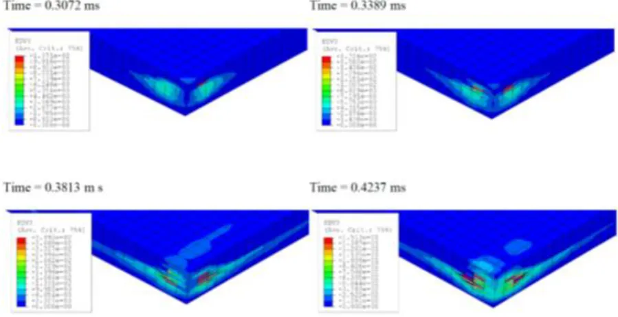
which are the Kühn-Tucker Conditions. An example of PDM can be visualised in Box I, see also Fig. 1 for an example of application of the PDM proposed in [24]. Among others the following PDMs can be highlighted:
– Lee (2001) [42] presented a progressive degradation model characterising the damage variables by means of Weibull function. He embedded the constitutive model within
DYNA3D and applied it to the simulation of damage on impact biaxial loading test and four-point bending test. Fibre debonding was modelled as prioritary damage mechanism adjusting the Weibull parameter. The algorithm was presented showing clear detail of the computation of damage using Weibull function. Further correlation to either experiments or against results from the literature could add-on to the relevance of such approach.
– Angioni et al. (2012) [1] proposed a combination of XFEM and multilevel mesh
7
BOX I: Example of PDM for composites
(For further details refer to Curiel-Sosa et al.(2013) [24] )
1. The stress is measured using the definition of effective stress σˆn by [18], Eq.(9). η is the internal damage vector. Subscript n denotes the time step in a marching numerical scheme.
n n
n D σ
σˆ (
) (9)2. The stress-strain relationship integrating the damage tensor D,
n n n n
n D C ε C ε
σ 1( ) 0 (10)
3. The stress damage surfaces (one per each damage mode ξ),
m
f(σn,ηn):σTn F(ηn)σn1 1,2,..., (11)
4. After mapping to the strain space, the damage surfaces become,
m
g(εn,ηn):εnTG(ηn)εn1 1,2,..., (12)
Where m n n T n
n) ( ) 1,2,...,
( C η F C η G (13)
5. Criteria for damage mode ξ initiation
m g
gn n0 n( n, n)0 1,2,...,
ε ε η (14)
6. The characterisation of damage mode directions d is given by,
m gn n T n T n
n: ( )/ 1,2,...,
G G ε d (15)
7. The potential growth of distinct damage modes is modelled as follows,
m gn n p
n : ( ) 1,2,...,
/ 1
ε (16)
8. Finally, the computation of damage internal variables rate as super- position of distinct damage modes,
m n n
n 1 d
η (17)
Angioni et al. results showed that the technique is convenient for the estimation of intralaminar stresses in composite laminates.
8
damage by means of X-ray NDT technique. In addition, the fracture criterion was also integrated in the model.
A drawback of using progressive damage models is their mesh dependency. To overcome this, regularisation approaches have already been proposed:
– Raimondo et al. (2012) [59] addressed the problem of damage localisation by regularisation techniques. These include a characteristic length, e.g. a side length of one element, within the constitutive relationship characterising the damage process.
[image:8.595.71.521.306.537.2]– Patel & Gupta (2014) [55] proposed a nonlocal progressive damage model for laminates based on nonlocal strain and damage variables. The computation of nonlocal variables is derived from the local ones by means of layerwise elements with quadratic variations. Although the approach is novel additional results in terms of stresses in this direction could provide further insight on the convenience of these approaches.
Figure 1. Example of simulation of progression of damage (delamination) on a cross-ply laminate subjected to low velocity impact by a rigid projectile. Data from [24]
2.2. Interface/cohesive elements for the progressive degradation of laminates
There have been numerous cohesive elements proposed for composite analysis in the last decade [4, 32, 69]. These special finite elements can split or divide subjected to a criterion or set of criteria. They are named in the literature in different ways: cohesive, decohesive or interface elements. They could be classified as:
• Smeared cohesive elements: in which the cohesive zone model is included on the
9
Below are presented some of the most interesting ones for simulating fracture on composites. Shi et al (2012) [64] incorporated solid-shell interface elements between laminae subjected to progressive degradation. The key point is that the interface element is not subjected to failure criteria for the splitting. Interestingly, they used a scalar parameter evolving in a
time-marching scheme that they integrated within ANSYS which is one of the few works in this direction.
3. Meshless Methods
Meshfree methods for the solution of partial differential equations in elasticity have come a long way since the very first papers of Libersky and co-workers on Smoothed Particle Hydrodynamics (SPH): in [44] a meshless method is applied for the first time in solid mechanics. The original versions of SPH lacked of the property of consistency (or reproducibility, i.e. the ability of the approximation to reproduce polynomial fields),
especially at the boundaries. The landmark papers by Belytschko and coworkers [9, 10, 11] on Element-Free Galerkin (EFG), contemporary with the papers by W.K.Liu and coworkers [21, 46, 47] on Reproducing Kernel Particle Method (RKPM), opened the way to the
widespread diffusion of meshfree methods for linear and nonlinear elasticity. Conversely from SPH, both methods satisfy reproducibility conditions, guaranteeing the mathematical prerequisites for convergence when used in a Galerkin formulation [36]. Both methods are substantially equivalent, though originated from different points of view: EFG from computer graphics, where Moving Least Squares (MLS) basis functions are used for surface
reconstructions from a cloud of scattered points; RKPM from wavelet theory. Still around that time, many other meshfree methods were developed, and a probably not comprehensive list includes: the Material Point Method (MPM) [62], the hp-clouds [2], Finite Point Method [54], the Free-Mesh method [76], the Meshless Local Petrov-Galerkin (MLPG) [3], Local Boundary Integral Equation (LBIE) [77], Natural Element Method [68], Meshless Finite Element Method (MFEM) [37], the Cracking Particles method [57] and lastly, peridynamics [65]. There is a reasonable large literature of applications of (various) meshfree methods to composite plates or, more generally, orthotropic materials: probably the very first work on material discontinuity (i.e. gradients of displacements are discontinuous) is [22] where inhomogeneities are treated by truncating the kernels at the material interface. We will, however, focus on modelling damage, and more generally, failure of composites with meshfree schemes. Meshfree methods can be broadly categorized (with some exceptions) in two categories: particle methods or Galerkin methods. Some authors [26] classify collocation methods (i.e. finite differences as a meshfree method as well, although these schemes are not well suited for Partial Differential Equations (PDE) containing discontinuities (where
derivatives are not defined in the classic sense) in their primary unknown, such as the displacements. In the particle methods, the history of state variables is tracked at discrete points (particles), without needing any mesh: these methods can be thought as physical particles interacting with each other, with their interaction regulated by some constitutive model. Examples of this class are the MPM and Peridynamics. In the Galerkin methods, the PDE is converted into a weak formulation, generating usually an algebraic system of
10
element-free version, where particles are more mathematical particles rather than physical particles (i.e. the vertices of the elements). SPH are, in this sense, a hybrid, since the
unknown in the original PDEs (usually balance laws) is approximated by its convolution with a kernel function, allowing derivatives of the approximation to be mathematically defined. The result is a particle-like method, where the constitutive interaction law derives directly from these convolution integrals. [20] for example used SPH to simulate fracture in
particulate composites, such as cement. [30] and [31] employed SPH to model bird-strike on a composite leading edge wing.
3.1. Peridynamics
An example of particle method is peridynamics, which can be thought as the continuum version of molecular dynamics: in fact, forces are exchanged only with the surrounding particles at a finite distance, and localization and subsequent fracture, are a consequence of the increase of the relative distance due to these forces. Using peridynamics, [75] simulated delamination and matrix damage process in composite laminates due to low velocity impact, whilst [41] described the process of fibre failure and damage initiation from the matrix for different fibre orientation. Recently, [35] showed dynamic brittle fracture for unidirectional fiber-reinforced composites, observing matrix–fiber splitting fracture, matrix cracking, and crack migration in the matrix, including crack branching in the matrix, using an homogenized model of the ensemble fibre-matrix.
3.2. Element Free Galerkin
Galerkin methods include EFG or RKPM, where test and trial functions are sets of Moving Least Squares (substantially equivalent to Reproducing Kernel Particle Methods). Two manners exist in the literature for introducing discontinuities: extrinsic and intrinsic. In extrinsic methods, similarly to XFEM, In [5, 6, 7] extrinsic enrichments are used to simulate benchmark cases (Double Cantilevered Beam, End Notched Flexure and End Loaded Split) delamination in layered composites for Mode I and II. [29] simulated mixed mode
delamination growth in composite beams, using Virtual Crack Closure Technique and an interaction power law to predict damage growth. [43] used Radial basis (RB) function and Moving Kriging (MK) interpolation in a Galerkin formulation to model the failure of two different unit cell models for woven composites: straight-edge and smooth fabric unit cell model. [61] used the visibility condition to build discontinuous meshfree shape function to model explicitly cracks and holes propagating inside a laminated composite.
4. Partition of Unity Methods
4.1. The eXtended Finite Element Method (XFEM)
The eXtended Finite Element Method (XFEM) is becoming very popular on the composite community for structural integrity analyses. This is because of the capability of XFEM to replicate virtual fracture without -or minimum-remeshing. This has two clear advantages:
11
• Introduction of the discontinuity associated to cracks, delamination, etc.
straightforward by means of additional degrees of freedom in the so-called enriched nodes. This provides a more realistic approach respect to the computation of jump in stress, strain and internal variables if it is to be compared with finite element methods including material constitutive relationships based on continuum damage mechanics alone.
XFEM falls within Partition of Unity Methods (PUM) category. PUM permits the
introduction of enrichment functions which may be replicated by the numerical strategy used. If the enrichment function are chosen discontinuous, then this allows the simulation of
discontinuities such as cracks. The enrichment is carried out in a part of the mesh. This part of the mesh will be able to replicate such discontinuities depending upon the enrichment type chosen. In particular, XFEM is integrating a PUM within a finite element context. Therefore, XFEM can be implemented straightforward within a FEM code.
4.1.1. How are cracks modelled within XFEM?
One great feature of XFEM is that the crack is allowed to split finite elements, i.e. it is not restricted to propagate between the finite elements boundary. In addition, no remeshing or very little remeshing is necessary. The modelling involves to select certain parts of the mesh for enrichment which can potentially allow the crack simulation if the constitutive behaviour requires it. In general, two types of enrichment functions are possible:
• Enrichment functions at crack tips to reproduce the asymptotic field
• Enrichment at the sides of current crack
Some remeshing is necessary in the case of extremely curved cracks
Note that the assignation of those enrichment will vary in a dynamic crack propagation. XFEM enriches the displacement approximation of the corresponding mesh nodes as follows,
(18)
2 1 ) ( ) ( ) ( ) ( ) ( ) ( k k k k j j j j i i
i N N
N b x x a x x u x x
u H H B B
where Ni,Nj denote finite element shape functions, ui the nodal displacements, and aj
and bk additional degrees of freedom for the displacement approximation. H(x) is a
Heaviside function taking the value +1 at one side of the crack and −1 in the opposite side of the crack. B(x) are support functions to replicate the asymptotic field ahead of the crack tip.
12
[image:12.595.106.499.71.231.2]
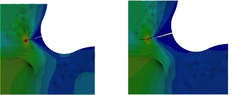
Figure 2. Illustrative detail of crack propagation using XFEM on a cruciform specimen designed for biaxial
loading tests. The sample, made of a glass reinforced polyester composite, is subjected to double load in the vertical arm than in the horizontal arm.
4.2. Phantom Node Method (PNM)
PNM is a variation of XFEM that allows the initiation of the cracks in any part of the mesh. However, a minimum distance between cracks has to be fixed when there is only one layer of finite elements. Seminal works on PNM applied to composites are proposed by Ling et al. (2009) [45] and van der Meer & Sluys (2009) [71]. In van der Meer (2010) [72] a
combination of PNM and cohesive elements is proposed for tackling matrix cracking and delamination respectively. In addition, [72] propose a continuum-based model for fibre failure. Their results in open-hole laminates justify such combination and tackle the size effect problem. However, doubts are risen about the PNM performance in composites failure prediction without such combination involving more than one technique which could be cumbersome for the software developer. Furthermore, the asymptotic field enrichment is not possible with PNM which leaves the special stress field ahead of the crack tip not properly simulated. PNM is a promising technique for replication of composite failure but
improvement will be needed to solve the aforementioned issues.
5. Multiscale and Homogenisation
Phenomena taking place at the macroscopic level are strictly related to the physics and mechanics of the background microstructure; the resulting overall behaviour of micro-non homogeneous materials, are strongly affected by the spatial distribution, size, shape, and mechanical properties of the constituents and of their joining interfaces at the microscopic level. The proper knowledge of the effective relation between microscale phenomena and the macroscopic behaviour, on one hand allows the overall description of multiphase materials, and on the other hand provides a microstructure design tool for the development of material having the required mechanical characteristics. A further potentiality of multiscale modelling is its capability to simply deal with the development of functional and smart materials
obtained from complex forming processes.
13
Under the undamaged material hypothesis, the simplest way to get the homogenised moduli of a heterogeneous material is based on the so-called rule of mixtures, operating through a weighted average (by using their volume fractions) over the properties of the constituents; this implies that only one microstructural characteristic, the volume ratio of the
heterogeneities, are taken into consideration in the average process. Starting from the 1970s, the fast development of micromechanics allowed to get a more effective and practical study of composite materials and structures; most of the early studies on this subject have been mainly devoted to theoretical modelling in the elastic behaviour regime.
Homogenisation approach for heterogeneous materials provides a rigorous method to
determine the macroscopic response of composite materials by accurately taking into account for microstructural characteristics and their evolution. The effective elastic medium
approximation – as proposed by Eshelby [25] and others Authors [33, 52] – is a more realistic model for heterogeneous materials: the properties of the macroscopically equivalent material, are obtained from the analytical solution of a boundary value problem (BVP) for an inclusion having a simple shape (such as an ellipsoid) embedded in an infinite matrix made of a different material. These approaches are suitable and give reasonable results when applied to heterogeneous materials having geometrical regularity, but they are not suitable – for example – for materials having clustered characteristics. The use of micro-macro strategy does not require the definition of constitutive equations at the macroscopic level that, in the case of complex microstructures, generally would be an awkward task. On the other hand the description of the constitutive behaviour at some macroscopic integration points (such those used in FE numerical quadrature formula) through homogenization techniques, operates by averaging the response of the deforming microstructure, enabling a straightforward
application of the method to geometrically and physically non-linear problems.
In order to deal with materials showing non-linear properties, an extension of the above mentioned self-consistent approach, has been proposed by introducing its incremental formulation [34].
The asymptotic homogenisation theory, based on the asymptotic expansion of displacement and stress fields on a material scale parameter (typically the heterogeneities characteristic size and a macrostructure length ratio), has also been developed, providing both the effective overall material properties as well as the local stress and strain values [12, 27, 38, 53]. The possibility to homogenize a composite material with a regular structure, i.e. the study of an equivalent homogeneous solid instead of the original inhomogeneous one, and the use of its effective properties, determined through the solution of so-called local problems formulated on the unit cell of the composite material, is one of the main capability of this approach.
14
The RVE can be defined as a statistically representative portion of the material, including a sampling of all possible microstructural configurations present in the composite; alternatively it can be considered as the smallest microstructural volume that properly represents the overall macroscopic properties.
Computational homogenisation have also been developed by applying numerical analyses on a RVE with proper boundary conditions in order to obtain the relation between the
macroscopic input and output quantities [51] . Such an approach for the mechanical characterisation of multiphase materials has several advantages such as the possibility to avoid the explicit knowledge of the macroscopic local constitutive equations (these are obtained by the solution of the corresponding microscale BVP), the possibility to include large strains as well as the nonlinear mechanical behaviour and the consideration of evolving microstructural information [17, 28, 39, 40, 60, 74].
Computational homogenisation technique has been recognised to be a useful and suitable tool to get the non-linear micro-macro structure-property relations, especially in the cases
involving a high complexity of the mechanical and geometrical microstructural properties by also allowing their eventual evolving character; other homogenisation methods cannot be competitive for such complex situations.
5.1. Energy-based homogenisation approach for short fibre-reinforced materials
Homogenisation-based approaches can be conveniently formulated through an energy, balance between the REV effective microstructure and its macroscopic counterpart [17, 39, 74]; in other words the assumption that the material at the microscale is energetically
equivalent to that at the macroscale is the main physical assumption of the method.
As a representative case, in the present section a fibre reinforced composite material will be considered for applying the above mentioned energy approach.
A FRC composite material is microscopically heterogeneous while it can be assumed to be macroscopically homogeneous if the fibres are uniformly dispersed in the matrix material; moreover if the fibres are randomly oriented in all the possible 3-D directions, the composite is also macroscopically isotropic, whereas the composite is macroscopically homogeneous and anisotropic (more precisely transversally isotropic) if the fibres are oriented by following a preferential direction.
The composite material is herein assumed to be characterized by macroscopical mechanical characteristics equal to those of a small reference elementary volume (RVE); moreover, for sake of simplicity, the fibres are assumed to be not interacting, that is to say that the so-called dilute composite hypothesis is made. Under such a hypotheses (often valid for fibre content not greater than about ~20%), the averaged properties of the composite can be easily determined.
15
deformation), matrix cracking, fibre debonding, fibre breaking, fibre buckling
(micro-buckling occurring in partially debonded fibres in periodic composites can be responsible for size effect and loss of the periodic structure characteristic) [74], etc. Among the above listed damage occurrences, fibre debonding is one of the most important [16, 17] and several technological researches have been performed in order to reduce such detrimental effect [48]. From the mechanical point of view the debonding phenomenon can be synthetically quantified through a scalar parameter s aimed at measuring the fibre-matrix strain mismatch or fibre-matrix sliding,
fm
[17]:(191)
fm
mf f
s mf mf s mf mf dm f )) ( 1 ( )) ( 1 ( :
k k ε or
(192) f mf s(mf )
where k (the unit vector identifying the fibre direction) has been introduced, f is the fibre
strain and mf is the matrix strain evaluated in the fibre direction. Values of s(mf ) tending to one indicate a perfect fibre-matrix bonding (i.e. no strain jump), while values of s(mf )
tending to zero denote a complete fibre-matrix detachment, i.e.
fm
mf ; for sake ofsimplicity in Eq. (19) the value s(mf ) can be considered as its averaged value evaluated along the fibre. The damage parameter in Eq. (191) , defined as d(1s), can be
considered as a measure of the composite damage associated with the fibre-matrix detachment.
By taking into account for such a degrading effect, by writing the energy equivalence over a suitable REV between the microscopically heterogeneous and the corresponding
macroscopically homogeneous one, the equivalent tangent stiffness tensor of the macroscopically homogenous fibre-reinforced material can be written [15]:
(20)
d p p dε ε ds ε s E m f m f m f m f f f m mh C Λ Λ
C' ' ' ( ) ( ) () ()
where the second order tensor Λ is defined as Λkk, E'f is the tangent elastic modulus of the fibres (evaluated with respect to the matrix strain in the fibre direction, i.e.
m f f
f d d
E' / ), m Vm/Vand f Vf /V are the matrix and fibre volume fractions, respectively, while the last integral is intended to be evaluated over the solid angle .
16
The fibre-matrix strain sliding value can be obtained from the knowledge of the strain distribution along a partially detached fibre; this results can be conveniently obtained by solving the corresponding fracture mechanics problem, related to the crack-like assumption of the fibre-matrix detached area [15], in order to get the current adhesion length; the fibre and matrix stress and strain can be finally estimated through the classical shear lag model [23].
By considering one single fibre as not influenced by the surrounding ones for sake of simplicity (for common FRC materials containing low fraction values of the reinforcing phase this usually applies), the remotely applied stress field can be decomposed along the axial and transversal fibre directions and the related mixed mode Stress-Intensity Factors (SIFs) can be obtained. The critical condition for incipient fibre debonding growth can be written as:
(21) KicAf,uf
Ki,eq , or
i eq i u f ic E K f A2 2, 2 ,
G
where A is a constant, depending on the fibre geometric and mechanical properties, and
Kieqf , is a function of the equivalent interface SIF, while Kic, Gic, f,u are the
characteristic values of the fibre matrix interface mechanical properties, i.e. the interface fracture toughness, interface critical fracture energy and fibre-matrix limit shear stress, respectively. The above equations provide a relationship linking the fracture and shear lag approach to fibre debonding.
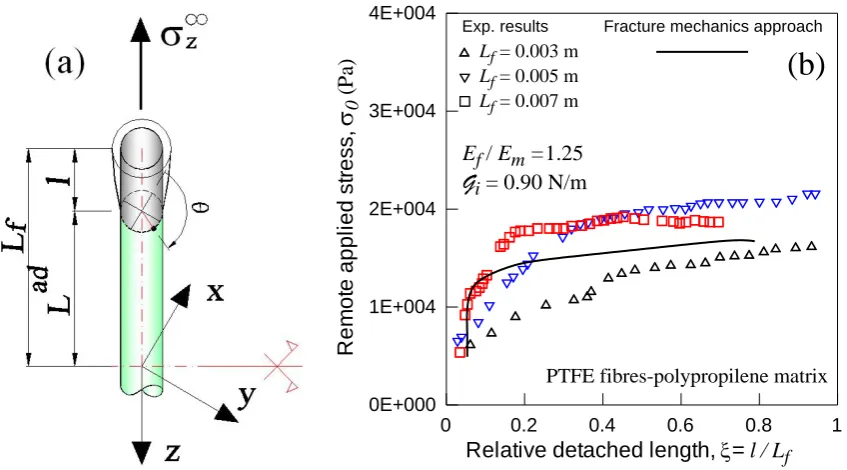
As an example in Fig. 3 the remote axial stress vs the dimensionless detached fibre length obtained through the above described fracture mechanics approach is represented and compared with experimental results [73].
0 0.2 0.4 0.6 0.8 1
Relative detached length, = l / Lf
0E+000 1E+004 2E+004 3E+004 4E+004 R e m o te a p p li e d s tr e s s , 0 (P a)
PTFE fibres-polypropilene matrix
Ef / Em =1.25
Gi= 0.90 N/m
(b)
Lf = 0.003 mLf = 0.005 m Lf = 0.007 m
[image:16.595.73.497.429.664.2]Exp. results Fracture mechanics approach
Figure 3. Partially debonded fiber, corresponding to a 3D fracture mechanics problem, under remote
axial (
z
) stress (a). Remote matrix stress vs the relative fiber debonding: experimental (Data from
[8]) and fracture mechanics results (b).
17
repeated loading such as fatigue in the high-cycle regime; proper crack growth rate laws allow the estimation of progressive and stable fibre detachment once the fatigue properties of the interface are known; on the other hand the fatigue damage occurring in the matrix can be also considered through classical damage accumulation evaluated through, for instance, the well-known empirical Wöhler or the Basquin models [8].
The mechanical degrading effects on the bulk material can be accounted for by the energy-based homogenisation approach through the actual matrix tangent stiffness tensor C'm (Eq. (20)), that can be evaluated on the basis of the current damage level corresponding to the load history applied to the composite. Damage produced by plastic deformation (such as for load level exceeding the elastic limit of the material or in cases of low-cycle fatigue), for metal or polymeric matrix materials, as well as damage corresponding to diffused or
concentrated cracks can be considered. As mentioned in the previous sections, the latter case requires proper regularisation techniques, such as non-local modelling or fracture
consistence energy based approaches, to avoid mesh-dependence [28] and get reliable results.
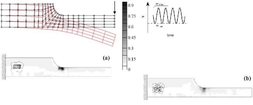
[image:17.595.81.506.377.553.2]A representative example of the fatigue-based damage approach to fibre debonding is given in Fig. 4 where a notched cantilever beam under fatigue bending (constant amplitude loading) is reported; both cases of aligned horizontal and random fibres are plotted.
Figure 4. Maps of the dimensionless debonded length l/Lf (see Fig. 2) for horizontal (a) and
random fibres distribution (b) in a notched beam under fatigue loading (f 3% ,
MPa 10
min max
) after 90000 cycles.
18 References
[1] S. L. Angioni, A. Visrolia, and M. Meo. Combining X-FEM and a multilevel mesh superposition method for the analysis of thick composite structures. Composites Part B: Engineering, 43(2):559–568, 2012.
[2] C Armando Duarte and J Tinsley Oden. Hp clouds-an hp meshless method. Numerical methods for partial differential equations, 12(6):673–706, 1996.
[3] SN Atluri and T1 Zhu. A new meshless local petrov-galerkin (mlpg) approach in computational mechanics. Computational mechanics, 22(2):117–127, 1998.
[4] C. Balzani and W. Wagner. An interface element for the simulation of delamination in unidirec-tional fiber-reinforced composite laminates. Engineering Fracture Mechanics, 75(9):2597–2615, 2008. cited By (since 1996)43.
[5] Ettore Barbieri and Michele Meo. A meshfree penalty-based approach to delamination in composites. Composites Science and Technology, 69(13):2169–2177, 2009.
[6] Ettore Barbieri. Meshfree methods for the analysis of composite materials. PhD thesis, University of Bath, 2010.
[7] Ettore Barbieri and Michele Meo. A meshless cohesive segments method for crack initiation and propagation in composites. Applied Composite Materials, 18(1):45–63, 2011.
[8] O. Basquin. The exponential law of endurance tests. In Proc. ASTM 10: 625–630, 1910.
[9] T. Belytschko, Y.Y. Lu, and L. Gu. Element-free Galerkin methods. International Journal for Numerical Methods in Engineering, 37(2):229–256, 1994.
[10] T. Belytschko, L. Gu, and YY Lu. Fracture and crack growth by element-free Galerkin methods. Modelling Simul. Mater. Sci. Eng, 2:519–534, 1994.
[11] T. Belytschko, YY Lu, and L. Gu. Crack propagation by element-free Galerkin methods. Engineering Fracture Mechanics, 51(2):295–315, 1995.
[12] A. Bensoussan, JL. Lionis and G. Papanicolaou. Asymptotic analysis for periodic structures. North-Holland, Amsterdam, 1978.
[13] P Berea, P Bercea, and O Nemesb. Phenomenological fracture model for biaxial fibre reinforced composites. Composites Part B: Engineering, 43:2237–2243, 2012.
[14] H Berger, U Gabbert, H Koppe, R Rodriguez-Ramos, J Bravo-Castillero, R Guinovart-Diaz, JA Otero, and GA Maugin. Finite element and asymptotic
homogenization methods applied to smart composite materials. Comput Mechs, 33:61– 67, 2003.
[15] R. Brighenti and D Scorza. A micro-mechanical model for statistically unidirectional and randomly distributed fibre-reinforced solids. Mathem. Mech. Sol., 17(8): 876–893, 2012.
19
[17] R. Brighenti and D. Scorza. Numerical modelling of the fracture behaviour of brittle materials reinforced with unidirectional or randomly distributed fibres. Mech. Mat., 52: 12–27, 2012.
[18] J-L. Chaboche. Continuous damage mechanics–a tool to describe phenomena before crack initiation. Nucl. Engng. Des., 64:233–247, 1981.
[19] Chaboche J-L. Lemaitre J. Mechanics of Solids Materials. Cambridge University Press, 1990.
[20] Yongqiang Chen and Sivakumar Kulasegaram. Numerical modelling of fracture of particulate composites using sph method. Computational Materials Science, 47(1):60–70, 2009.
[21] J-S Chen, Chunhui Pan, Cheng-Tang Wu, and Wing Kam Liu. Reproducing kernel particle methods for large deformation analysis of non-linear structures. Computer Methods in Applied Mechanics and Engineering, 139(1):195–227, 1996.
[22] LW Cordes and B Moran. Treatment of material discontinuity in the element-free galerkin method. Computer Methods in Applied Mechanics and Engineering, 139(1):75–89, 1996.
[23] HL. Cox. The elasticity and strength of paper and other fibrous materials. Br. J. Appl. phys. 3: 72–79, 1952.
[24] J.L. Curiel Sosa, S. Phaneendra, and J.J. Munoz. Modelling of mixed damage on fibre reinforced composite laminates subjected to low velocity impact. International Journal of Damage Mechanics, 22(3):356–374, 2013.
[25] J. D. Eshelby. The determination of the field of an ellipsoidal inclusion and related problems, Proc. R. Soc. Lond A 241: 376–396, 1957.
[26] T.P. Fries and H.G. Matthies. Classification and overview of meshfree methods. Brunswick, Institute of Scientific Computing, Technical University Braunschweig, Germany. Informatik-bericht Nr, 3, 2003.
[27] S. Ghosh, K. Lee and S. Moorthy. Two scale analysis of heterogeneous elastic–plastic materials with asymptotic homogenisation and Voronoi cell finite element model, Comput. Meth. Appl. Mech. Eng. 132: 63–116, 1996.
[28] F. Greco and R. Luciano. A theoretical and numerical stability analysis for composite microstructures by using homogenization theory, Compos. Part B 42(3): 382–401, 2011.
[29] I Guiamatsia, BG Falzon, GAO Davies, and L Iannucci. Element-free galerkin modelling of composite damage. Composites Science and Technology, 69(15):2640– 2648, 2009.
[30] M Guida, F Marulo, Michele Meo, A Grimaldi, and G Olivares. Sph–lagrangian study of bird impact on leading edge wing. Composite Structures, 93(3):1060–1071, 2011.
20
[32] R. Haj-Ali. Cohesive micromechanics: A new approach for progressive damage modeling in laminated composites. International Journal of Damage Mechanics, 18(8):691–719, 2009.
[33] Z. Hashin. The elastic moduli of heterogeneous materials, J. Appl. Mech. 29: 143–150, 1962.
[34] R. Hill. A self-consistent mechanics of composite materials, J. Mech. Phys. Solids 13: 213–222, 1965.
[35] Wenke Hu, Youn Doh Ha, and Florin Bobaru. Peridynamic model for dynamic fracture in unidirectional fiber-reinforced composites. Computer Methods in Applied Mechanics and En-gineering, 217:247–261, 2012.
[36] T.J.R. Hughes. The Finite Element Method. Dover, 1987.
[37] Sergio R Idelsohn, Eugenio Onate, Nestor Calvo, and Facundo Del Pin. The meshless finite element method. International Journal for Numerical Methods in Engineering, 58(6):893–912, 2003.
[38] AL. Kalamkarov, I.V. Andrianov andV.V. Danishevs’kyy. Asymptotic homogenization of composite materials and structures. Appl. Mech. Rev. 62(3), 2009.
[39] AL. Kalamkarov and HQ. Liu. A new model for a multiphase fibre-matrix composite materials. Composites Part B, 29: 643–653, 1998.
[40] AL Kalamkarov and AV Georgiades. Micromechanical modeling of smart composite structures. Smart Materials and Structures, 11: 423–434, 2002.
[41] B Kilic, A Agwai, and E Madenci. Peridynamic theory for progressive damage
prediction in center-cracked composite laminates. Composite Structures, 90(2):141–151, 2009.
[42] H.K. Lee. A computational approach to the investigation of impact damage evolution in discontinuously fiber reinforced composites. Computational Mechanics, 27(6):504– 512, 2001.
[43] LY Li, MH Aliabadi, and Pi Hua Wen. Meshfree continuum damage mechanics modelling for 3d orthogonal woven composites. Key Engineering Materials, 488:759– 762, 2012.
[44] Larry D Libersky and AG Petschek. Smooth particle hydrodynamics with strength of materials. In Advances in the Free-Lagrange Method Including Contributions on Adaptive Gridding and the Smooth Particle Hydrodynamics Method, pages 248–257. Springer, 1991.
[45] D. Ling, Q.D. Yang, and B.N. Cox. An augmented finite element method for modeling arbitrary discontinuities in composite materials. Int J Fract, 156(1):53–73, 2009.
21
[47] WK Liu, Sukky Jun, Shaofan Li, Jonathan Adee, and Ted Belytschko. Reproducing kernel particle methods for structural dynamics. International Journal for Numerical Methods in Engineering, 38(10):1655–1679, 1995.
[48] G-Y. Lu and Y-W Mai. Effect of plastic coating on fibre-matrix interface debonding. J. Mat. Sci (30): 5872–5878, 1995.
[49] AR Maligno, NA Warrior, and AC Long. Finite element investigations on the microstructure of fibre-reinforced composites. Express Polymer Letters, 2: 665–676, 2008.
[50] A. Matzenmiller, J. Lubliner, and R.L. Taylor. A constitutive model for anisotropic damage in fiber-composites. Mechanics of Materials, 20:125–152, 1995.
[51] J. C. Michel, H. Moulinec and P. Suquet. Effective properties of composite materials with periodic microstructure: a computational approach, Comput. Meth. Appl. Mech. Eng. 172: 109–143, 1999.
[52] T. Mori and K. Tanaka. Average stress in the matrix and average elastic energy of materials with misfitting inclusions, Acta Metall. 21: 571–574, 1973.
[53] S. Nemat-Nasser and M. Hori. Micromechanics: overall properties of heterogeneous materials. Elsevier, Amsterdam, 1993.
[54] E Onate, S Idelsohn, OC Zienkiewicz, and RL Taylor. A finite point method in computational mechanics: applications to convective transport and fluid flow.
International Journal for Numerical Methods in Engineering, 39(22):3839–3866, 1996.
[55] BP Patel and AK Gupta. An investigation on nonlocal continuum damage models for composite lami-nated panels. Composites: Part B, 60:485–494, 2014.
[56] A Puck and Schurmann. H. Failure analysis of frp laminates by means of physically based phenomenological models. Composites Science and Technology, 58:1045–1067, 1998.
[57] T Rabczuk and T Belytschko. Cracking particles: a simplified meshfree method for arbitrary evolving cracks. International Journal for Numerical Methods in Engineering, 61(13):2316– 2343, 2004.
[58] FKF Radtke, A Simone, and LJ Sluys. A partition of unity finite element method for obtaining elastic properties of continua with embedded thin fibres. International Journal for Numerical Methods in Engineering, 84(6):708–732, 2010.
[59] L. Raimondo, L. Iannucci, P. Robinson, and P. T. Curtis. A progressive failure model for mesh-size-independent fe analysis of composite laminates subject to low-velocity impact damage. Composites Science and Technology, 72(5):624–632, 2012.
[60] M. Romanowicz. Numerical homogenization of fiber-reinforced composites with complex microstructural features. J. of Theor. and Appl. Mech. 51(4): 883–890, 2013
22
[62] D Sulsky, Zhen Chen, and Howard L Schreyer. A particle method for history-dependent materials. Computer Methods in Applied Mechanics and Engineering, 118(1):179–196, 1994.
[63] Y. Shi, T. Swait, and C. Soutis. Modelling damage evolution in composite laminates subjected to low velocity impact. Composite Structures, 94(9):2902–2913, 2012.
[64] G. Shi, H. Zhang, J. Wang, and Z. Wang. Progressive delamination simulation of laminated plates based on a solid-shell interface element with damage-node model. Procedia Engineering, 31:324–330, 2012.
[65] Stewart Andrew Silling and Ebrahim Askari. A meshfree method based on the peridynamic model of solid mechanics. Computers & Structures, 83(17):1526–1535, 2005.
[66] P. M. Suquet. Homogenization techniques for composite media. Lecture Notes in Physics, vol. 272. Springer, 1987.
[67] P. M. Suquet. Local and global aspects in the mathematical theory of plasticity, in Plasticity Today: Modelling, Methods and Applications, eds. A. Sawczuk and G. Bianchi, Elsevier Applied Science Publishers, London, 279–310, 1985.
[68] Natarajan Sukumar. The natural element method in solid mechanics. PhD thesis, Northwestern University, 1998.
[69] T.E. Tay, G. Liu, V.B.C. Tan, X.S. Sun, and D.C. Pham. Progressive failure analysis of composites. Journal of Composite Materials, 42(18):1921–1966, 2008.
[70] K. Terada and N. Kikuchi. A class of general algorithms for multi-scale analysis of heterogeneous media, Comput. Meth. Appl. Mech. Eng. 190: 5427–5464, 2001.
[71] F.P. Van der Meer and L.J. Sluys. A phantom node formulation with mixed mode cohesive law for splitting in laminates. Int J Fract, 158(2):107–124, 2009.
[72] F.P. Van der Meer and L.J. Sluys. Mesh-independent modeling of both distributed and discrete matrix cracking in interaction with delamination. Eng Fract Mech, 77(4):719– 735, 2010.
[73] C. Wang. Fracture mechanics of single-fiber pull-out test. J. Mat. Sci. 32: 483–490, 1997.
[74] N Willoughby, WJ Parnell, AL Hazel, and ID Abrahams. Homogenization methods to approximate the effective response of random fibre-reinforced composites. International Journal of Solids and Structures, 49:1421–1433, 2012.
[75] Jifeng Xu, Abe Askari, Olaf Weckner, and Stewart Silling. Peridynamic analysis of impact damage in composite laminates. Journal of Aerospace Engineering, 21(3):187– 194, 2008.
23
[77] Tulong Zhu, J-D Zhang, and SN Atluri. A local boundary integral equation (lbie) method in computational mechanics, and a meshless discretization approach. Computational Mechanics, 21(3):223–235, 1998.