THE DESIGN OF A ROBOTIC ARM LINK USING FUNCTIONALLY GRADED MATERIALS: A CASE STUDY
Mr Thomas A. M. McMastera*, Prof. Xiu T. Yana
a Department of Design, Manufacture and Engineering Management, University of Strathclyde, Glasgow, Scotland,
UK, G1 1XQ, [email protected] * Corresponding Author
Abstract
The development and design of a functionally-graded material (FGM) robotic arm for supporting and manipulating a vision system is discussed in this paper. The aim is to understand if using FGMs effectively reduce mass compared to single material parts. The evolution of ideas using topological optimisation (TO) and FGMs towards the design are shown and reviewed. The final design uses TO, and as such needs to be manufactured using additive manufacture (AM). Constraints have been put in place to ensure physical manufacturability is possible. The final design reduces the mass compared to the original arm by 61.4%.
Keywords: Robotic Arm, Functionally Graded Materials, Additive Manufacture, Topology Optimisation
1. Introduction
Portrayed as ``the robot revolution'' [1], the short-term future will see the robotics industry go through large-scale growth [2, 3]. As such, research into robotics is ever-increasing. Creating lightweight robots is one area of research interest - past robots have been structurally cumbersome to ensure stiffness and safety factor values [4]. Within the field of lightweight robotics, reduction of actuator and drive train mass has received significant attention. Chedmail and Gautier [5] developed a method for an optimised selection of off-the-shelf components for actuators. The solver chooses the lightest combination of components available that can adhere to the task-specific design. Other research on lightweight actuation has looked at new actuation designs, such as cable drive, whereby all drive systems are kept in the base of the robotic arm, and pneumatic muscle drive, whereby air is used to manipulate the arm. Similar to optimised actuator choice from off the shelf components, Zhou et al. [6] created a design approach for choosing the lightest combination of drive train components. Pettersson et al. [7] did work on optimal design of two drive trains on a six DOF manipulator, focussing on cost and performance. Part of the work by Albu-Schaffer et al. [8, 9, 10] focussed on redesign of the drive train to reduce the weight while increasing the accuracy.
Comparatively little work has been done on the links themselves [11]. To address this gap, the work in this paper does some preliminary tests using FGMs to create a design for a lightweight robotic arm link, based on a link currently in use within the research facility at the university.
2. Description of Work
The case study aims to test the use of FGMs for reducing the mass of the present robotic arm, while satisfying the constraints currently in place. The results from the FGM parts will be compared to those simulated from single materials.
2.1. Robotic Arm Model
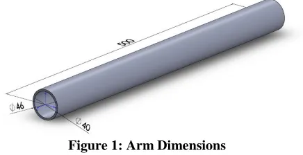
[image:1.612.329.547.458.570.2]The robotic arm used in the case study is a cylindrical pipe. It has the dimensions illustrated in Figure 1 (a 3mm wall thickness).
Figure 1: Arm Dimensions
2.2. Arm Specifications/Assumptions/Constraints
The specifications, constraints and assumptions for the robot arm are as follows:
- One end of the model is fully fixed to simulate the end of the link that is attached to the base of the robot.
- Primary Constraint:
o The free end of the arm link has a displacement constraint of 0.25 mm. Secondary Constraints:
o The arm should be as light as possible. o The arm must be
physically-manufacturable.
- The arm is controlling the positioning of a large field-of-view vision system, and therefore no account is made for stiffness of the arm to reduce vibrations, as is often needed in robotic arms.
- All material combinations used in the dual material analysis can be successfully bonded together.
3. Original Arm
The arm was originally constructed from grade six aluminium (Al6061-T6). As such, it currently has a mass of 0.547 kg. The aim of this case study is to reduce the mass of the arm while adhering to the displacement constraint.
4. New Arm
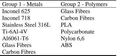
[image:2.612.317.552.242.427.2]It has been foreseen that the results from this case study will produce a geometrically-complex structure for the robotic arm. As such, additive manufacture (AM) will be used in its construction. Therefore, only materials currently process able using AM will be tested. Looking at the capabilities of a prominent additive manufacturing company, the materials shown in Table 1 are chosen for testing.
Table 1: FGM Testing Materials
Group 1 - Metals Group 2 - Polymers Inconel 625 Glass Fibres Inconel 718 Carbon Fibres Stainless Steel 316L PLA
Ti-6Al-4V Polycarbonate Al6061-T6
Glass Fibres Carbon Fibres
Nylon 6,6 ABS
4.1. Single Material
As a basis, each of these materials were first assigned individually to the model in Figure 1 to test their capabilities.
4.2. Dual Distinct Material
The materials were combined on the tube to create models with two distinct material regions. All materials from Table 3 were tested. However, not all these materials can be bonded to one another (it is very difficult to bond polymers and metals). Since one constraint is to ensure manufacturability, the materials were split into two groups, as shown in Table 1. Both groups had the ceramic composites within.
The two distinct materials can be placed onto the cylindrical tube both along its length (see Figs 2(a) and 2(b)), and radially (whereby the material alters over the cross section - see Figs 2(c) and 2(d)).
(a) Along Tube 1st Material (b) Along Tube 2nd Material
[image:2.612.78.276.497.592.2](c) Radial 1st Material (d) Radial 2nd Material
Figure 2: Material Configurations
These first dual material models have kept the two materials separate, in their own distinct areas. This is not ideal, as it creates stress concentrations and non-ideal bending characteristics. These are seen in Fig. 3(a). Fig. 3(a) shows that the maximum stress is at the boundary where the two materials meet. It also shows that the right-hand side of the tube remains near-straight, while the left-hand side displaces significantly across its length. This is a result of the material on the right-hand side being far stiffer than that on the left-hand side. To compensate for these issues, functionally graded materials (FGMs) will be investigated.
(a) Distinct Material (b) FGM
4.3. FGM
Functionally graded materials (FGMs) are designed to continuously blend material properties throughout a part, in one or more directions [12]. This allows the advantageous properties of two materials, for example, the toughness of a metal and the corrosion resistance of a ceramic [13] to be exploited while reducing stress concentrations that are seen when the materials are homogeneous (Fig. 3(a)) Many FGM implementations have blended the materials extremely smoothly, either by altering the material properties at each gauss point(s) of every element in a finite element mesh [14] or by using a isoparametric formulation [15]. While this gives the greatest reduction in stress concentrations, it makes the parts physically un-manufacturable, as such material blends cannot be produced. Since the part must remain physically-manufacturable, the material gradation in this work is limited.
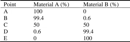
The tube is separated into 30 segments along its length and 30 segments radially, totalling 900 segments overall. The tube has a 3mm wall thickness, so the smallest dimension of a segment is therefore 0.0001 m (0.003 m ÷ 30). Segments with dimensions of this size can be physically produced using AM technology [16, 17]. As noted by Kim et al [18] the layer thickness of any AM part should be a multiple of the minimum resolution capable by the AM hardware. The dimensions in this part satisfy this constraint. The material properties are the same within each segment, but are graded between segments. Taking the model in Figure 1 and slicing it along the y-z plane gives Figure 4. The material properties are set to alter by a percentage of the largest distance on the model, whereby the largest distance on this model is from the inner radius point on the left-hand edge (point ``A'') to the outer radius point on the right-hand edge (point ``E''), as shown in Figure 4. Table 2 shows the material percentage at various points on the tube. This percentage alteration value is calculated from the physical size of the segment when compared to the largest dimension - the higher the number of segments for a given space (making each segment smaller), the lower the alteration values between each segment. This allows two materials to be gradually combined, removing the high stress concentrations between the materials. An example is shown in Fig 3(b).
[image:3.612.319.541.94.166.2]Figure 4: Material Percentages
Table 2: Material Percentages
Point Material A (%) Material B (%)
A 100 0
B 99.4 0.6
C 50 50
D 0.6 99.4
E 0 100
4.4. Topological Optimisation
TO aims to optimise a design space by re-arranging (both addition and removal) material within the space to satisfy given design responses, such as weight, displacement and strain energy, while adhering to given constraints [19, 20]. In these tests, the strain energy is being solved for while the volume fraction has a fixed target. The SIMP TO method is being used - it decides which element of material to re-arrange based on the density of that element [21]. The aim of using TO on the robotic arm was to discover which material combinations could be further reduced in weight while still maintaining the 0.25 mm displacement constraint. Each material combination was assessed. Every combination was tested with 13 different volume fractions - from 20\% to 80\% at 5\% increments. A minimum feature size was set to ensure the parts could still be manufactured using AM.
5. Results and Discussion
The results based on the tests outlined above are provided below.
5.1. Single Material
The single material results are split into two categories: solid tube and TO tube.
5.1.1. Solid Tube
the polymers pass the secondary constraint (mass), they have failed as they do not meet the primary constraint.
If these results are used, all the polymers and GF must be excluded, as they do not satisfy the primary constraint. However, if these ``failed'' materials are combined with
those that passed the primary constraint, the mass of any of these material combinations could be lower when compared to any of the successful solid tube results in Table 3. For this reason, all materials are kept for the dual material tests.
Table 3: Single Material Results
Solid TO
Material Maximum
Displacement (mm)
Mass (kg) Maximum Displacement (mm)
% Material Remaining
Mass (kg)
Inconel 625 0.077 1.710 0.245 25 0.428
Inconel 718 0.080 1.660 0.230 25 0.415
Stainless Steel 316L 0.083 1.620 0.208 30 0.486
Ti-6Al-4V 0.141 0.898 0.228 40 0.359
Al6061-T6 Carbon Fibres Glass Fibres Polycarbonate Nylon 6,6 ABS PLA
0.233 0.222 0.353 4.580 5.300 6.420 7.240
0.547 0.324 0.405 0.263 0.233 0.211 0.243
0.249 0.241 - - - - -
65 65 - - - - -
0.356 0.211 - - - - -
5.1.2. TO Tube
The three right-most columns of Table 3 show the single material TO results. All materials which failed the primary constraint when the tube was solid were not tested, as they would still fail after TO (when the tube is already solid, no more material can be added). As mentioned, the TO tests were undertaken at 5% increments between 20% and 80%. Table 3 shows only the lightest successful result for each material from the solid tube test, along with the percentage of material (to the nearest 5%) remaining in the tube when it satisfied the displacement constraint.
As seen, all masses dropped considerably. Whereas when the tubes were solid and only CFRP passed the constraint and was lighter than the current Al6061-T6 tube, all tubes are now lighter than the current Al6061-T6 tube, as seen in Table 3.
5.2. Dual Material
The dual material results are split into three categories: distinct material, FGM and FGM+TO.
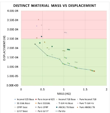
5.2.1. Distinct Material
Figure 5: Configuration Results
All but one of the 36 material configurations fail in the polymer combinations. Since said materials failed both the single material tests (in Table 3) and these tests, they are ruled out from any further testing. Looking at the results of the metal combinations, many pass the constraint. Focussing on the combinations along the pareto front, it is seen that neither Al6061-T6 or GF appear (either in “pure” form, or combined with another material). For this reason, Al6061-T6 and GF are also excluded from further tests.
5.2.2. FGM
The remaining materials (Inconel 625, Inconel 718, Stainless Steel 316L, Ti-6Al-4V and CF) were tested again. The material combinations which satisfied the
displacement constraint, along with the volume fraction at which they passed, are shown in
Table 4. The mass and displacement results of the FGM results are similar to those from the distinct dual material tests. However, the uniform bending and uniform stresses make the FGM parts more desirable than the distinct material parts (which have non-uniform bending and large stress concentrations).
5.2.3. FGM+TO
Table 4: FGM Results
FGM FGM + TO
Material Maximum
Displacement (mm)
Mass (kg) Maximum Displacement (mm)
% Material Remaining
Mass (kg)
Inc 625 + Inc 718 0.108 1.658 0.242 35 0.580
Inc 625 + SS 316L 0.109 1.638 0.246 35 0.573
Inc 625 + Ti-64 0.128 1.283 0.250 40 0.519
Inc 625 + CF 0.144 1.000 0.244 45 0.450
Inc 718 + Inc 625 Inc 718 + SS 316L Inc 718 + Ti-64 Inc 718 + CF SS 316L + Inc 625 SS 316L + Inc 718 SS 316L + Ti-64 SS 316L + CF Ti-64 + Inc 625 Ti-64 + Inc 718 Ti-64 + SS 316L Ti-64 + CF CF + Inc 625 CF + Inc 718 CF + SS 316L CF + Ti-64
0.110 0.112 0.132 0.149 0.112 0.114 0.135 0.153 0.156 0.159 0.161 0.226 0.209 0.213 0.216 0.268 1.658 1.614 1.258 0.976 1.638 1.614 1.239 0.957 1.283 1.258 1.239 0.601 1.000 0.976 0.957 0.601 0.240 0.249 0.248 0.249 0.244 0.250 0.218 0.223 0.234 0.239 0.243 0.247 0.241 0.245 0.250 - 35 35 40 45 35 35 45 50 45 45 45 70 60 60 60 - 0.580 0.568 0.512 0.442 0.573 0.565 0.557 0.478 0.557 0.478 0.577 0.421 0.600 0.586 0.547 -
6. Comparison of Test Methods
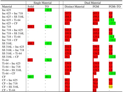
[image:6.612.100.514.116.399.2]Table 5 shows the results of all tests spoken of above. The material abbreviations used are as follows: Inc 625 = Inconel 625, Inc 718 = Inconel 718, SS 316L = Stainless Steel 316L, Ti64 = Ti-6Al-4V, CF = Carbon fibre. Results are given in \% rather than absolute mass values. The current solid Al6061-T6 tube is the reference, and all figures are normalised to it. Those in Table 5 with positive values (in red) are heavier than the original tube, by that percentage value. Those with negative values (in green) are lighter than the original tube, by that percentage value.
Table 5 shows FGM parts have similar masses as distinct material parts.
The “FGM+TO” results show that the parts are lighter than the ``FGM'' results, as expected.
However, the “FGM+TO” parts are heavier than the “Single Material TO” parts. The reason is due to the
limited number of materials available for AM. Carbon fibre has by far the greatest strength to weight ratio of any of the AM process able materials. Therefore, when used on its own (as a single material), it gives a displacement to mass ratio which is far better than that of any material blend (any FGM).
Table 5: Summary of Test Results
Single Material Dual Material
Material Solid TO Distinct Material FGM FGM+TO
Inc 625 212.6 - 21.8 - - -
Inc 625 + Inc 718 - - 207.9 203.1 6.0
Inc 625 + SS 316L - - 204.3 199.5 4.8
Inc 625 + Ti-64 - - 137.0 134.6 - 5.1
Inc 625 + CF - - 83.7 82.8 - 17.7
Inc 718 203.3 - 24.1 - - -
Inc 718 + Inc 625 Inc 718 + SS 316L Inc 718 + Ti-64 Inc 718 + CF SS 316L
SS 316L + Inc 625 SS 316L + Inc 718 SS 316L + Ti-64 SS 316L + CF Ti-64
Ti-64 + Inc 625 Ti-64 + Inc 718 Ti-64 + SS 316L Ti-64 + CF CF
CF + Inc 625 CF + Inc 718 CF + SS 316L CF + Ti-64
- - - - 196.3 - - - - 64.1 - - - - -40.7 - - - - - - - - - 11.2 - - - - - 34.4 - - - - -61.4 - - - - 208.0 199.8 132.5 79.2 - 204.6 199.9 129.0 75.7 - 139.6 134.9 131.3 10.8 - 88.1 83.4 79.8 12.6 203.1 195.0 129.9 78.4 - 199.5 195.0 126.5 74.9 - 134.6 129.9 126.5 9.9 - 82.8 78.4 74.9 9.9 6.0 3.8 - 6.4 - 19.2 - 4.8 3.3 1.8 - 12.6 - 5.5 3.5 1.8 - 23.0 - 9.7 7.1 0.0 -
7. Conclusion
This paper shows the evolution of design for a FGM robotic arm link. When combining FGM with TO, lightweight parts can be created. If the application calls for a lightweight arm a differing environment (e.g, variable temperature environment), it could be advisable to make the arm link from separate materials. If this is the case, the materials should be blended together gradually, as this gives uniform stress distributions and uniform bending characteristics. However, if no harsh environments are encountered, it is best to make the robotic arm link out of a single material - the one with the greatest stiffness to weight ratio. As the list of materials available for AM increases, the functionality and viability of FGMs will increase.
8. Acknowledgements
This work acknowledges funding from the following sources: Engineering and Physical Sciences Research Council (EPSRC) Grant No. EP/IO15698/1, University of Strathclyde (including the faculty of engineering and the department of design, manufacture and engineering
management (DMEM)) and the China Academy of Launch Vehicle Technology (CALT).
References
[1] M. Rosoff, “The mobile revolution is over. Get ready for the next big thing: Robots.,” Business
Insider UK. [Online]. Available:
http://uk.businessinsider.com/robots-are-the-next-wave-of-computing-2016-1.
[2] C. Chambers, “Investors Take Note, The Next Big Thing Will Be Robots,” Forbes Investing.
[Online]. Available:
http://www.forbes.com/sites/investor/2014/11/2 5/investors-take-note-the-next-big-thing-will-be-robots/%5C#6bada80c4d9c.
[3] M. Ford, Rise of the Robots: Technology and the Threat of a Jobless Future. Basic Books, 2015. [4] G. M. Mair, Industrial Robotics. Prentice Hall,
1988.
[5] P. Chedmail and M. Gautier, “Optimum Choice of Robot Actuators,” J. Manuf. Sci. Eng., vol. 112, no. 4, pp. 361–367, 1990.
560–569, 2011.
[7] M. Pettersson and J. Ölvander, “Drive Train Optimization for Industrial Robots,” IEEE Trans. Robot., vol. 25, no. 6, pp. 1419–1424, 2009.
[8] A. Albu-Schäffer, O. Eiberger, M. Fuchs, M. Grebenstein, S. Haddadin, C. Ott, A. Stemmer, T. Wimböck, S. Wolf, C. Borst, and G. Hirzinger, “Soft Robotics: From Torque Feedback Controlled Lightweight Robots to Intrinsically Compliant Systems,” Robot. Res., vol. 70, pp. 185–207, 2011.
[9] A. Albu-Schaffer and G. Hirzinger, “State feedback controller for flexible joint robots: A globally stable approach implemented on DLR’s light-weight robots,” IEEE Int. Conf. Intell. Robot. Syst., vol. 2, pp. 1087–1093, 2000. [10] A. Albu-Schäffer, S. Haddadin, C. Ott, A.
Stemmer, T. Wimböck, and G. Hirzinger, “The DLR lightweight robot: design and control concepts for robots in human environments,” Ind. Robot An Int. J., vol. 34, no. 5, pp. 376–385, 2007.
[11] L. Zhou and S. Bai, “A New Approach to Design of a Lightweight Anthropomorphic Arm for Service Applications,” J. Mech. Robot., vol. 7, no. 3, pp. 31001-31001–12, 2015.
[12] T. Hirano, J. Teraki, and T. Yamada, “On the design on functionally gradient materials,” in Proceedings of 1st International Symposium on Functionally Gradient Materials, 1990, pp. 5– 10.
[13] S. Gouasmi, A. Megueni, A. S. Bouchikhi, K. Zouggar, and A. Sahli, “On the Reduction of Stress Concentration Factor Around a Notch Using a Functionally Graded Layer,” Mater.
Res., vol. 18, pp. 971–977, 2015.
[14] W. G. Buttlar, G. H. Paulino, and S. H. Song, “Application of graded finite elements for asphalt pavements,” J. Eng. Mech., vol. 132, no. 3, pp. 240–249, 2006.
[15] J.-H. Kim and G. H. Paulino, “Isoparametric Graded Finite Elements for Nonhomogeneous Isotropic and Orthotropic Materials,” J. Appl. Mech., vol. 69, pp. 502–514, 2002.
[16] M. Vaezi, S. Chianrabutra, B. Mellor, and S. Yang, “Multiple material additive manufacturing – Part 1: a review,” Virtual Phys. Prototyp., vol. 8, no. 1, pp. 19–50, 2013.
[17] A. Zocca, P. Colombo, C. M. Gomes, and J. Günster, “Additive Manufacturing of Ceramics: Issues, Potentialities, and Opportunities,” J. Am. Ceram. Soc., vol. 98, no. 7, pp. 1983–2001, 2015. [18] H. Kim, J.-W. Choi, and R. Wicker, “Scheduling and process planning for multiple material stereolithography,” Rapid Prototyp. J., vol. 16, no. 4, pp. 232–240, 2010.
[19] G. I. N. Rozvany, “A critical review of established methods of structural topology optimization,” Struct. Multidiscip. Optim., vol. 37, no. 3, pp. 217–237, 2009.