(will be inserted by the editor)
Bandwidth Study of the Microwave Reflectors with
Rectangular Corrugations
Liang Zhang · Wenlong He · Craig R. Donaldson · Adrian W. Cross
Received: 07 December 2015; Revised: 24 January 2016; Accepted: 23 April 2016
Abstract The mode-selective microwave reflector with periodic rectangular corrugations in the inner surface of a circular metallic waveguide is studied in this paper. The relations between the bandwidth and reflection coefficient for different numbers of corrugation sections were studied through a global optimization method. Two types of reflectors were investigated. One does not consider the phase response and the other does. Both types of broadband reflectors operating at W-band were machined and measured to verify the numerical simulations.
Keywords periodic waveguide · broadband reflector · mode matching method
1 Introduction
Metallic waveguides with periodic structures have very interesting features that have attracted extensive research in the last few decades [1]. They can support a slow electromagnetic wave which can be efficiently coupled with a low relativistic electron beam to generate coherent radiation. Because of this coupling, periodic metallic waveguides are widely used in microwave vacuum electron devices (MVEDs) such as backward wave oscillators (BWOs), travel-ling wave tubes (TWTs) and magnetrons [2, 3].
From the Floquet theory, the electromagnetic fields supported in a peri-odic structure may be represented by an infinite set of spatial harmonics [4]. This representation may be used to calculate the coupling between different
L. Zhang, W. He, C. R. Donaldson, and A. W. Cross
Department of Physics, SUPA, University of Strathclyde, Glasgow, G4 0NG, UK Tel.: 44-0141 548 4812
Fax: 44-0141 552 2891
into a hybrid TE11/TM11 mode to generate a quasi Gaussian beam [7, 8].
Other mode converters have also been developed, such as TE11to TEm1 and
TM01 to TE31 [9, 10]. The synchronism conditions provide the possibility to
design a mode convertor between any two suitable modes. Helically corru-gated waveguide that contains both axial and azimuthal periodicities can be used to support the fast wave-beam interaction. Because of its inherently wide bandwidth, it attracts significant interest in gyrotron backward wave oscilla-tors (gyro-BWOs) and gyrotron travelling wave tube amplifiers (gyro-TWAs) [11–13].
If the waveguide is without azimuthal periodicity and its axial period sat-isfies the Bragg resonance condition 2k1= 2π/d, the axial periodic waveguide
structure would scatter the incident wave coherently into a backward wave to achieve a mode selective reflection. A strong resonance Bragg cavity can be produced by two such axial periodic structures. A narrow band free electron laser (FEL) using the Bragg resonator was experimentally demonstrated in Ka-band and proved the advantages of high output power and high interac-tion efficiency [14, 15].
A periodic waveguide used as a mode-selective reflector can be used to sep-arate the microwaves from the electron beam in a MVED. In many cases this is accomplished by using a cutoff waveguide. For high frequencies, the cutoff radius becomes small, limiting the current of the electron beam and there-fore limiting the power that the device can produce. A periodically-corrugated waveguide on the other hand can be operated in overmoded conditions. It could have a much larger radius than a cutoff waveguide, allowing higher electron beam currents hence higher microwave output power.
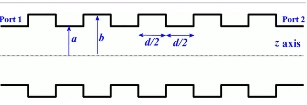
Different axial periodic corrugation profiles such as sinusoidal, trapezoidal, and rectangular can be used. The rectangular corrugation profile is shown in Fig. 1. It includes two circular waveguide sections with radii a and b in one period. This profile has a simple structure making it easy to fabricate [16, 17]. In addition, it can be quickly and accurately analyzed by mode matching techniques. Because of these advantages, the rectangular corrugation profile is studied in this paper.
Fig. 1 The rectangular corrugation circular waveguide.
would help to improve the mode purity as well as the bandwidth [18]. A gen-eral rectangular corrugation circular waveguide that has corrugation sections with arbitrary radii and lengths may achieve even wider bandwidth. However to reduce the number of the free parameters, in this paper, the corrugation sections were assumed to have the same length but with different radii. A global optimization method was used to fully study the bandwidth property of such rectangular corrugated reflectors.
2 NUMERICAL SIMULATIONS
Different methods can be used to calculate the scattering characteristics of the rectangularly corrugated waveguides. The coupled-wave theory is fast, howev-er, it does not take account possible mode conversions at a large corrugation depth.
Numerical methods based on discrete meshes such as the finite elemen-t meelemen-thod (FEM) and elemen-the finielemen-te-difference elemen-time-domain (FDTD) meelemen-thod can also be used [19]. However, they usually result in long computing times and re-quire large computing resources. The mode matching method provides a fast and accurate solution for such corrugation structures. It divides the waveg-uide structure into radial discontinuities and regular sections. The fields at both sides of a discontinuity are written as the sum of modal fields of the regular cylindrical waveguide. By matching the fields at the discontinuity, the coupling coefficient between each mode can be determined. From these cou-pling coefficients, the scattering matrix is formed for the discontinuity. The overall scattering parameters of the entire waveguide can be obtained by cas-cading all the scattering matrices of all discontinuities and regular waveguide sections. The drawback of the mode matching method is that only a limited type of waveguide discontinuity can be solved analytically. Fortunately the rectangular corrugation circular waveguide is one of these. The details of cal-culating and cascading scattering matrices of a circular waveguide with radial steps can be found in [20–23].
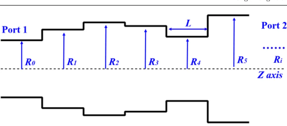
Fig. 2 The rectangular corrugation circular waveguide.
points in the interested range have to be calculated and evaluated. In order to achieve the maximum bandwidth, a global optimization algorithm, multiple-object genetic algorithm [24], was employed to find the optimal performance. A number of initial candidate solutions, which is also called initial population, are evaluated by a goal function and evolved to achieve better solutions. The evolution of the candidate solutions is achieved by the genetic operations in-clude selection, mutation, and crossover. After a certain generations, the values of the goal function can converge, which means the optimization has achieved optimal parameters. The parameters used in the genetic algorithm, such as the population size, the crossover and mutation probability can affect the con-vergence speed. In our simulation, to achieve a good coverage of the parameter space, large population size of 96 and generation number of 1000 were chosen although long simulation time is required. The crossover probability and the mutation probability were chosen as 0.85 and 0.05, respectively.
Compared with single-objective optimization which provides one single op-timal value, there are usually a number of parameter sets that may satisfy the optimal condition of the goal functions in the multiple-objective optimiza-tion. This bunch of non-dominanted points distributed in different areas of the goal functions is called Pareto Front and the corresponding parameter sets are called Pareto Set. The multiple-objective optimization provides a better understanding of the goal functions as it suggests an area of the Pareto Fron-t. It is very useful for investigating the relations among the goal functions. When the multiple-objective optimization is finished, the optimal parameters can be chosen from the Pareto Set which is normally a tradeoff between the goal functions.
In the optimization of the rectangularly corrugated waveguide, the radius Ri and the length of each corrugation section L are the parameters to be
3 PERFORMANCE OF THE REFLECTORS
As a perfect reflector, the waveguide short has unity reflectivity and a phase shift of 180 degrees for all frequencies. Therefore in this paper, the performance of two types of reflectors were studied. The first type was from optimizations that only calculated the reflection coefficient at input port 1 (S11) without
taking account the phase response. The second type took both the reflection coefficient and phase spread at input port 1 (S11) into considerations, where
the phase response was defined by 2π−(|P11(f1)|+|P11(f2)|). P11(f1) and
P11(f2) are the phase part of the complex reflection coefficient after
unwrap-ping at the interested frequencies of f1 and f2. The waveguide short has a
phase spread of 0 and the design reflector is preferred to have small phase spread value as well.
The simulation frequency range in this paper was W-band (75 -110 GHz) as the results could be directly used in the W-band gyro-BWO project [25]. The center frequency was set at 95 GHz. The operating mode was TE11. The radius
of the first sectionR0 was fixed to be 1.30 mm (with a cutoff frequency 67.6
GHz of the TE11mode). The radii of the corrugation sectionsRi, i= 1,2,3, ...
were set as optimizing variables in the range of 1.3-3.0 mm and they are larger thanR0. The length of the corrugation sectionsLwas allowed to vary in the
ranges of 0.2-6.0 mm.
3.1Reflector without considering the phase response
In this case, the optimization goals were to maximize the average reflection coefficient S11 and the bandwidth. The bandwidth was defined as the
fre-quency range centered at 95 GHz frefre-quency having a reflection coefficient of
≥0.98). A 13-section reflector was previous designed for an X-band gyro-BWO whose operating frequency range is 8.0-9.5 GHz to separate the spent electron beam and the microwave radiation [26]. It is possible to increase the operating bandwidth by increasing the number of corrugation sections.
Fig. 3 shows the optimized bandwidth and the S11 coefficient for
differ-ent numbers of corrugation sections calculated by using the mode matching method. Generally the bandwidth and reflection coefficient increase as the number of corrugations increase. However from the simulation when the cor-rugation section number reached beyond 22, the bandwidth and reflection did not increase much. In reality when manufacturing the reflector, the number of corrugation sections may be limited since more sections increase not only manufacturing difficulty, but also cost and Ohmic loss.
Fig. 3 Calculated bandwidth and reflection coefficient as a function of the number of cor-rugation sections.
satisfying the required bandwidth and reflection coefficient conditions, thereby reducing computing time.
As the goal functions of the optimization do not consider the phase infor-mation, the phase spread is large after unwrapping, as shown in Fig. 4(b). This is not desired in applications that require a smooth changing phase response such as a linear amplifier.
3.2Reflector considering phase response
In wide bandwidth amplifier, when the corrugation structure is used in a mi-crowave coupler and acts as a waveguide short, the geometry is required to produce a high reflection coefficientS11as well as a small phase spread around
πin the operating frequency range. A larger phase spread of the reflector will result in a smaller bandwidth of the input coupler [27]. To optimize a reflector for amplifiers, the goal functions need to take the phase response into account. Two goal functions were set in the multiple-objective genetic algorithm opti-mization. One is to maximize the reflection and bandwidth, and the other is to minimize the unwrapped phase spread, as shown in equ. 2.
f1(x) =
N
∑
F
[A11(x, F)−1] 2
/N
f2(x) = MAX(UNWRAP(P11(x))−MIN(UNWRAP(P11(x)))
(a)
(b)
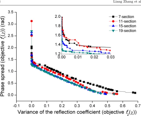
Fig. 5 the Pareto front of the goal functions. The inset plot shows the Pareto front in a smaller value range.
where xare the parameters to be optimized.F is the frequency index in the calculated frequency range, N is the number of frequencies to be calculated, A11is the reflection coefficient amplitude derived from theS11parameter and
P11 is the phase of S11.
Fig. 5 shows the Pareto fronts of the goal functions in different numbers of corrugation sections. The trends at the left side show a very high reflection can be achieved (the variance of theA11close to 0) if a large phase spread is
acceptable. This agrees with the results from the first type. The final choice should be a compromise of the two requirements. Also the simulations showed that, increasing the number of corrugation section may not help to get a better performance if it exceeds 15. The optimization results also indicated that a small corrugation length was required (<0.8 mm) to get small phase spread, while the corrugation length could be much larger (∼3.5 mm) for the case without considering phase response.
4 MEASUREMENT OF THE REFLECTORS
Fig. 6 Photos showing the manufacture process of the reflectors (a) the Aluminum man-drels, (b) the 18-section reflector (c) the 15-section reflector.
the phase response, was used to separate the radiation and the spent electron beam so that an energy recovery system could be applied. A 15-section reflec-tor acted as a waveguide short considering the phase spread was designed for a side-wall coupler [28]. The radius of the first sectionR0was set as 1.3 mm,
and the rest corrugation sections are with radii larger than 1.3 mm (Ri≥1.3
mm). If using a cut-off waveguide as the microwave reflector, the maximum radius would have been 0.84 mm (with a cutoff frequency 104.6 GHz of the TE11mode). Using the Bragg reflector gives a factor of 1.5 increase of
waveg-uide radius. The section lengthsLof the 18 and 15 section reflectors were 4.02 mm and 0.76 mm, respectively.
The reflectors were fabricated through the electroforming method. Firstly aluminum mandrels with the inner cross-section of the waveguides were made (Fig. 6(a)) and then copper was electroformed on them. Finally the aluminum mandrels were dissolved away in alkali to leave the copper waveguides as shown in Fig. 6.
Fig. 7 shows the measurement setup using a vector network analyzer (V-NA). Rectangular-to-circular transitions and circular tapers were used between the reflector and the VNA ports (which have rectangular apertures) to reduce the reflection in the measurement. The S-parameters and the phase evolution of the setup with and without reflector were measured separately. The scat-tering parameters and the phase of the reflectors were obtained by taking the difference of the results.
Fig. 8 The simulated and measured transmissions and reflections of the 18-section broad-band reflector.
the waveguide. The reflection coefficientS11of the measurement was slightly
lower than the simulated one because of Ohmic loss. More than 93% (-0.3 dB) of the microwave signal was reflected back to the incident port.
Fig. 9 The simulated and measured reflection coefficientS11 and phase response of the 15-section broadband reflector.
5 CONCLUSION
In this paper, the metallic microwave reflectors with rectangular corrugations were studied. The relation between the bandwidth and reflection coefficient as a function of corrugation sections were studied numerically through global optimization method. Optimization of the reflectors for both a case considering phase and a case without considering phase were studied. Without considering phase spread the reflector could achieve a better performance by increasing the number of corrugated sections. Furthermore, the length of each section could be large enough to relax machining tolerances. In the applications that requires a small phase spread, one needs to compromise between the reflection coefficient and the phase spread when choosing the geometry parameters. The simulations showed that more than 15 corrugation sections did not improve performance. Also a relatively short section length was required to get a small phase spread. To verify the simulation results, reflectors operate in W-band were fabricated and measured. A good agreement between simulation and experimental measurement was found.
6. L. Zhang, W. He, K. Ronald, A. Phelps, C. Whyte, C. Robertson, A. Young, C. Don-aldson, A. Cross, IEEE Trans. Microw. Theory Techn.60(1), 1 (2012)
7. P.J.B. Clarricoats, A.D. Olver, Corrugated Horns for Microwave Antennas (London, U.K.: Peregrinus, 1984)
8. P. McElhinney, C. Donaldson, L. Zhang, W. He, IEEE Trans. Antennas Propag.61(3), 1453 (2013)
9. D. McDermott, J. Pretterebner, C. Chong, C. Kinney, M. Razeghi, J. Luhmann, N.C., IEEE Trans. Microw. Theory Techn.44(2), 311 (1996)
10. G.G. Denisov, S.V. Samsonov, D.I. Sobolev, Radiophys. and Quantum Electronics 49(12), 961 (2006)
11. A.W. Cross, W. He, A.D.R. Phelps, K. Ronald, C.G. Whyte, A.R. Young, C.W. Robert-son, E.G. Rafferty, J. ThomRobert-son, Appl. Phys. Lett.90, 253501 (2007)
12. W. He, A.W. Cross, A.D.R. Phelps, K. Ronald, C.G. Whyte, S.V. Samsonov, V.L. Bratman, G.G. Denisov, Appl. Phys. Lett.89, 091504 (2006)
13. L. Zhang, S.V. Mishakin, W. He, S.V. Samsonov, M. McStravick, G.G. Denisov, A.W. Cross, V.L. Bratman, C.G. Whyte, C.W. Robertson, A.R. Young, K. Ronald, A.D.R. Phelps, IEEE Transactions on Microwave Theory and Techniques63(3), 1090 (2015) 14. N.S. Ginzburg, A.A. Kaminsky, A.K. Kaminsky, N.Y. Peskov, S.N. Sedykh, A.P.
Sergeev, A.S. Sergeev, Phys. Rev. Lett.84, 3574 (2000)
15. S.J. Cooke, A.W. Cross, W. He, A.D.R. Phelps, Phys. Rev. Lett.77, 4836 (1996) 16. D. Wagner, W. Bongers, W. Kasparek, F. Leuterer, F. Monaco, M. Munich, H. Schutz,
J. Stober, M. Thumm, H.v. Brand, EPJ Web of Conferences87, 04012 (2015) 17. E. de Rijk, A. Macor, J.P. Hogge, S. Alberti, J.P. Ansermet, Review of Scientific
In-struments82(6), 066102 (2011)
18. C.K. Chong, D.B. McDermott, M.M. Razegh, N.C. Luhmann, J. Pretterebner, D. Wag-ner, M. Thumm, M. Caplan, B. Kulke, IEEE Trans. Plasma Sci.20(3), 393 (1992) 19. C.S. SUITETM, (CST AG, Germany, available at www.cst.com)
20. T.S. Chu, T. Itoh, IEEE Trans. Microw. Theory Techn.34(2), 280 (1986) 21. G.L. James, IEEE Trans. Microw. Theory Techn.29(10), 1059 (1981)
22. J. Neilson, P. Latham, M. Caplan, W. Lawson, IEEE Trans. Microw. Theory Techn. 37(8), 1165 (1989)
23. E. T. Itoh,Numerical techniques for microwave and millimeter-wave passive structures
(New York: Wiley, 1989)
24. C.A. Coello Coello, IEEE Comput. Intell. Mag.1(1), 28 (2006)
25. W. He, C.R. Donaldson, L. Zhang, K. Ronald, P. McElhinney, A.W. Cross, Phys. Rev. Lett.110, 165101 (2013)
26. L. Zhang, W. He, A. Cross, A. Phelps, K. Ronald, C. Whyte, IEEE Trans. Plasma Sci. 37(3), 390 (2009)
27. L. Zhang, W. He, C. Donaldson, J. Garner, P. McElhinney, A. Cross, IEEE Trans. Microw. Theory Techn.63(10), 3183 (2015)