City, University of London Institutional Repository
Citation
:
Martinez Estelles, Sylvia (2016). Study and suppression of vibrations in rotary-wing Unmanned Aerial Vehicles. (Unpublished Doctoral thesis, City, University of London)This is the accepted version of the paper.
This version of the publication may differ from the final published
version.
Permanent repository link: http://openaccess.city.ac.uk/17441/
Link to published version
:
Copyright and reuse:
City Research Online aims to make research
outputs of City, University of London available to a wider audience.
Copyright and Moral Rights remain with the author(s) and/or copyright
holders. URLs from City Research Online may be freely distributed and
linked to.
City Research Online: http://openaccess.city.ac.uk/ [email protected]
City University London
School of Mathematics, Computer
Science and Engineering
PhD thesis
Study and suppression of
vibrations in rotary-wing
Unmanned Aerial Vehicles
Silvia Estell´es Mart´ınez
supervised by
Dr. M. Tom´
as-Rodr´ıguez
October 2015
School of Mathematics, Computer
Science and Engineering
City University London
Study and suppression of
vibrations in rotary-wing
Unmanned Aerial Vehicles
Silvia Estell´es Mart´ınez
1
stSupervisor:
Dr. Mar´ıa
Tom´
as-Rodr´ıguez
2
ndSupervisor:
Prof. George
Halikias
Submitted as part of the requirements for the degree of Doctor of Philosophy
Contents
Acknowledgments 21
Abstract 23
1 Introduction 33
1.1 Unmanned Aerial Vehicles (UAVs) . . . 33
1.2 Motivation and objectives . . . 38
1.3 Thesis outline . . . 40
1.4 Thesis contributions . . . 41
2 Literature review 43 2.1 History of unmanned and rotary-wing vehicles . . . 43
2.2 Quadrotors in the modern era . . . 51
2.3 Contribution to the state of the art . . . 62
3 Quadrotor modelling 65 3.1 Quadrotor dynamic and aerodynamic overview . . . 65
3.1.2 Aerodynamic forces involved . . . 72
3.2 Modelling tool: VehicleSim . . . 75
3.2.1 VehicleSim modelling software, VS-Lisp . . . 77
3.2.2 Equations of motion . . . 81
3.2.3 VehicleSim solvers . . . 84
3.2.3.1 Overview of numerical integration methods . . . 85
3.2.3.1.1 Adams-Moulton 2nd Order Method . . . 87
3.2.3.1.2 Adams-Moulton 3rd Order Method . . . 87
3.2.3.1.3 Adams-Moulton 4th Order Method . . . 88
3.2.3.1.4 Runge-Kutta 2nd Order Method . . . 88
3.2.3.1.5 Adams-Bashforth 2nd Order Method . . 89
3.3 Structural modelling . . . 89
3.3.1 Rigid blades’ model. . . 91
3.3.2 Elastic blades’ model. . . 92
3.4 Aerodynamic modelling . . . 97
3.4.1 Aerodynamic forces as a function of the rotational speed. . 99
3.4.2 Aerodynamic forces as a function of the rotational and translational speed. . . 101
3.4.2.1 Aerodynamic forces as a function of the rotational and translational speed applied at the blade’s sta-tionary pressure centre. . . 102
3.4.3 Aerodynamic forces for elastic blades. . . 105
3.4.4 Obtaining the aerodynamic parameters . . . 108
3.5 Summary of the chapter . . . 110
4 Control system 113 4.1 Analysis of the nonlinear mathematical model . . . 113
4.2 Controllability of the platform . . . 117
4.3 Control method . . . 121
4.3.1 Description of the algorithm . . . 122
4.3.2 Control of Drag Moments . . . 127
4.3.2.1 Counter Drag Moment as a function of the rota-tional speed. . . 128
4.3.2.2 Counter Drag Moment as a function of the rota-tional and translarota-tional speed. . . 129
4.3.2.3 Counter Drag Moment for elastic blades. . . 130
4.3.3 Predefined smooth references . . . 131
4.4 Trajectory tracking results . . . 134
4.5 Summary of the chapter . . . 140
5 Vibrations 143 5.1 Vibrational analysis . . . 144
5.1.1 Static and dynamic characterization of elastic blades . . . 144
5.2 Oscillations appearing in the angular acceleration. . . 153
5.2.1 Predictor-corrector process for angular acceleration oscilla-tions. . . 155
5.3 Different blade mass and blade fracture . . . 159
5.3.1 Controllability of a different mass blade system. . . 160
5.3.2 Behaviour of a mass defective blade or fractured blade quadro-tor . . . 163
5.3.3 Adaptive control for moderate structural damage . . . 165
5.3.4 Isolating control device for severe structural damage . . . . 167
5.3.4.1 Description of the isolating control device . . . . 168
5.3.4.2 Preliminary study of the isolating control device . 168 5.3.4.3 Application of the isolating control device . . . . 170
5.4 Summary of the chapter . . . 173
6 Conclusions and future work 175 6.1 Summary . . . 175
6.2 Conclusions . . . 177
6.3 Future work guidelines . . . 178
6.4 List of contributions . . . 179
A Calculus of the representative point of the blade 181
B Calculus of the representative point of the blade’s segment for
elastic blades 185
D Calculus of the pressure centre of the blade’s segment for elastic
blades. 189
E Moments’ relation to maintain the forces balance 191
City, University of London Northampton Square London EC1V 0HB United Kingdom
T +44 (0)20 7040 5060
THE FOLLOWING PARTS OF THIS THESIS HAVE BEEN REDACTED
FOR COPYRIGHT REASONS:
Figure 1.1: Predator in military use
Figure 1.2: Left: Yamaha RMax UAV, conventional helicopter configuration Right: Draganflyer X6, multi-rotor configuration
Figure 1.3: High Altitude Airship, by Lockheed Martin [4]. Delfly flapping wing UAV, developed at the Micro Air Vehicle Lab of the Delft University of
Technology
Figure 2.1: An artist depiction of the ying pigeon, the first documented UAV in history.
Figure 2.2: Typical Chinese top
Figure 2.8: Convertawings revived the concept tried in France by Oemichen and by G. de Bothezat in the United States, 1956
List of Tables
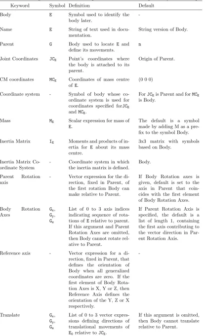
3.1 Degrees of freedom and parameters for defining a body in VS-Lisp 79
3.2 Parameters defining forces and moments in VS-Lisp . . . 80
3.3 Aerodynamic parameters of quadrotor courtesy of ai2 . . . 108
4.1 Parameters values for the system’s bodies in VS-Lisp. . . 117
4.2 Control parameters. . . 126
List of Figures
1.1 Predator in military use . . . 34
1.2 Left: Yamaha RMax UAV, conventional helicopter configuration. Right: Draganflyer X6, multi-rotor configuration. . . 34
1.3 High Altitude Airship, by Lockheed Martin. Delfly flapping wing UAV, developed at the Micro Air Vehicle Lab of the Delft
Univer-sity of Technology. . . 35
1.4 Number of UAV related publications per year. Source google scholar. 36
1.5 Annual funding profile of the US Department of Defense for UAVs. 37
1.6 Annual funding profile in Europe for UAVs. . . 37
2.1 An artist depiction of the flying pigeon, the first documented UAV in history. It is reported that it flew about 200 meters. . . 44
2.2 Typical chinese top. . . 44
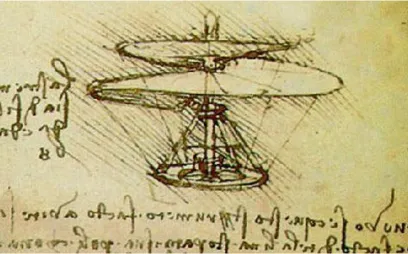
2.3 ’If this instrument made with a screw be well made - that is to say,
made of linen of which the pores are stopped up with starch and be turned swiftly, the said screw will make its spiral in the air and
it will rise high.’ - Leonardo Da Vinci, 15th century. . . 45 2.4 Left: Launoy & Bienvenu’s invention, 1784. Right: Sir George
Cayley’s helicopter, 1796. . . 46
2.6 Oehmichen No. 2 design picture. On May 4th 1924, it was the first helicopter to fly the distance of one kilometer in a closed-circuit,
landing at its starting point. . . 48
2.7 The de Bothezat helicopter, known as the ”Flying Octopus”, un-dergoes a test flight, 1923. . . 49
2.8 Convertawings revived the concept tried in France by Oemichen
and by G. de Bothezat in the United States, 1956. . . 50
2.9 Image of the Curtiss-Wright VZ-7, a quadrotor configuration heli-copter designed for the US army in the 1950’s. . . 51
3.1 Representative diagram of two-bladed rotors’ and blades’
posi-tion around the central body, with the inertial reference system ([Xn,Yn,Zn]), the body-based reference system ([XSTR,YSTR,ZSTR]) and
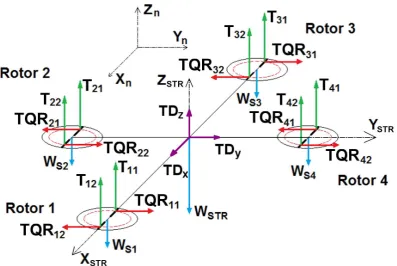
the forces involved in the quadrotor dynamics: Thrust (T), Torque/Radius (T QR), Translational Drag (T D) and Weight (W) forces. . . 67
3.2 Different coordinate system for the definition of the aerodynamic
resultant force (RF). Lift (L) and Drag (D) forces are normal and parallel to the incident airflow respectively, Thrust (T) and
Torque/Radius (T QR) forces are normal and parallel to the rotor plane respectively. . . 67
3.3 Representative diagram of rotors’ location around the central body
and motions of the quadrotor. The X(t) and Y(t) motions repre-sented correspond to a positive pitch and roll motion, respectively. 69
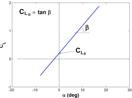
3.4 A typical curve showing section the Lift coefficient versus angle of attack for a cambered airfoil. It does not include the stall
phe-nomenon since it has not been modelled in this work. . . 74
3.5 A typical drag polar curve for a cambered airfoil. . . 75
3.7 Interconnection diagram of VehicleSim components and other soft-wares employed in the simulations. . . 76
3.8 Example of Cartesian coordinate systems associated to different
bodies in VS-Lisp and their parent-child structure. . . 78
3.9 Sketch of the time discretization of a state variable xand its time derivative ˙x. . . 86
3.10 Sketch of the time discretization for the half-step numerical
inte-gration. . . 87
3.11 Left: Schematic sketch of quadrotor’s bodies distribution and the structure’s and rotors’ associated axes for rigid blades. Right:
Parent-child structure employed in the definition of the quadrotor as a multibody system, with blade i1 considered rigid and blade i2
considered elastic. . . 90
3.12 Sketch of rotor number 2, S2, including rigid blades’ distribution
and associated axes. . . 91
3.13 Representation of a blade discretization in a single element, with
rotational spring for the elastic and vibrational characterization and damper for the dynamic characterization. . . 94
3.14 Blade discretization inn elements, with rotational spring as
equiva-lent of the elastic properties and damper as equivaequiva-lent of structural damping. . . 95
3.15 Adjusted dynamic displacement of the balsa wood discretized beam
tip when initially disturbed (-·-) and expected decay of the contin-uous beam oscillations amplitude (—): Aoe−2πξωnt . . . 96
3.16 Equivalence between Torque/Radius forces, T QRi, and Drag
Mo-ment, DMi, acting on the rotor i. . . 98
4.1 Comparison of responses to step and smooth reference signals for different longitudinal displacements on the Xn axis. (a) 1 meter
translation. (b) 5 meters translation. (c) 10 meters translation. (d) 20 meters translation. . . 132
4.2 Comparison between the control actions that lead to 1 (a) and 5 (b) meters of longitudinal displacement. Smooth reference inputs
(- - -), step reference inputs (—). . . 133
4.3 Example of fifth order trajectory signals generated by Matlab and applied to the quadrotor. . . 134
4.4 Example of quadrotor trajectories tracking and errors for different models: reference signals (—), rigid simple model (- - -), rigid
complete model (-·-). (a) Translation error on the Xn axis. Inset:
7 m translation on the Xn axis. (b) Translation error on the Yn
axis. Inset: 3 m translation on the Yn axis. (c) Translation error
on the Zn axis. Inset: 1 m translation on the Zn axis. (d) Yaw
rotation error around the Zn axis. Inset: 90 yaw rotation around
the Zn axis. . . 135
4.5 Comparison of the control actions that lead in the movements
shown in Figure 4.4 for different models: rigid simple model (-- (--), rigid complete model (···). (a) Control moment applied to
ro-tor 1. (b) Control moment applied to roro-tor 2. (c) Control moment applied to rotor 3. (d) Control moment applied to rotor 4. . . 136
4.6 Example of the oscillations appearing in the Lift generated by blades B11 and B21 when the lateral and longitudinal trajectories
shown in Figure 4.4 are followed. . . 137
4.7 Three-dimensional helical trajectory tracking using the rigid
4.8 Three-dimensional rectangular trajectory tracking using the rigid complete aerodynamic model. (—) is the reference signal and (·)
is the rigid complete model trajectory. . . 138
4.9 Control moments applied to obtain the three-dimensional helical
trajectory shown in Figure 4.7. . . 139
4.10 Control moments applied to obtain the three-dimensional
rectan-gular trajectory shown in Figure 4.8. . . 139
5.1 Left: Usual stiffness distribution in a helicopter blade. Rigth:
Elas-tic blade modelled with a rigid segment close to the root and two elastic double length segments with flap degree of freedom. . . 145
5.2 Representation of the blade discretization in a rigid segment next to the root of lengthr1 and two equal double length segment with
flap degree of freedom of length 2r1. Equivalent number of
seg-ments of equal length r1, nt = 5, equivalent number of segments
with flap degree of freedom of equal lengthr1, nf = 4. . . 146
5.3 Blade’s first and second natural frequencies’ variation with
elastic-ity and rotational speed. Continuous lines represent the theoretical frequencies (5.2- 5.3); the dots represent the frequencies obtained
with the VehicleSim simulation for different materials; and the dif-ferent colors represent the difdif-ferent rotational speeds (Ω = 0 (blue),
100 (red), 200 (green), 300 (cyan), 400 (magenta) rad/s). . . 147
5.4 Comparison of the pitch amplitude for a usual tridimensional
5.5 Comparison of the vehicle’s pitch acceleration amplitude for a usual tridimensional trajectory (Xref
n = 7 m, Ynref = 3 m, Znref
= 1 m) when rigid and elastic blades of different materials are considered and details at different times. (a) Detail of acceleration
between 0.50 and 0.55 s time. (b) Detail of acceleration between 2.65 and 2.75 s time. (c) Detail of acceleration between 4.15 and
4.20 s time. (d) Detail of acceleration between 6.30 and 6.40 s time.151
5.6 Comparison of the vehicle’s pitch acceleration’s frequency spectra
for the usual trajectory and different materials, including the alu-minium, which is prone to resonance for the given flight conditions. 152
5.7 Vibrational spectrum of the pitch speed and position compared to
the magnitude of the vibrational spectrum of the pitch acceleration for a usual tridimensional trajectory (Xref
n = 7 m,Ynref = 3 m,Znref
= 1 m). . . 154
5.8 Total control moment applied to rotor 1 in order to follow the
trajectoryXnref = 7 m,Ynref = 3 m,Znref = 1 m when the complete aerodynamic model is considered. . . 155
5.9 Comparison of the pitch acceleration when the aerodynamic
com-plete and aerodynamic simple models are considered for the con-ventional trajectory tracking (Xref
n = 7 m, Ynref = 3 m, Znref = 1
m). . . 156
5.10 Comparison between the pitch acceleration when the same
trajec-tory is applied (Xnref = 7 m, Ynref = 3 m,Znref = 1 m) to different aerodynamic models: complete model, corrected model and simple
model. . . 158
5.11 Comparison between the complete model and the corrected model
control actions, for the same trajectory (Xnref = 7 m, Ynref = 3 m,
Zref
5.12 (a) Centrifugal forces acting on the two rotating blades of a com-pensated rotor. (b) Centrifugal force decompensation appearing
in the rotor when a rotating blade with different mass is considered.159
5.13 Centrifugal force transmitted to the vehicle along the XSTR and
YSTR axis when a complete blade is missing in rotor 1, prescribed
trajectories Xref
n = 0 m, Ynref = 0 m,Znref = 0 m. . . 160
5.14 (a) Unsaturated control actions (CM) required to follow the pre-scribed trajectories with a 5 % defective mass blade, showing the
exponential envelope of the curve (CM envelope) and the rotor’s working limits (CMmax,CMmin). (b) Prescribed trajectoriesXnref
= 7 m,Ynref = 3 m, Znref = 1 m) and vehicle tracking. . . 164
5.15 (a) Saturated control actions (CM) required to follow the
pre-scribed trajectories with a 5 % defective mass blade, showing the rotor’s working limits (CMmax, CMmin). (b) Prescribed
trajec-tories and vehicle tracking (Xnref = 0 m, Ynref = 0 m, Znref = 0 m). . . 164
5.16 (a) Saturated control actions (CM) required to follow the pre-scribed trajectories with a 5 % length broken blade, showing the
rotor’s working limits (CMmax, CMmin). (b) Prescribed
trajec-tories and vehicle tracking (Xref
n = 0 m, Ynref = 0 m, Znref = 0
m). . . 165
5.17 Response of the platform and control action leading to it when the
modified adaptive PVA control system is applied to the vehicle for different length of broken blade: (a) Trajectory tracking with 15%
of blade length broken. (b) Control moment applied to rotor 1 that lead to trajectories shown in (a). (c) Trajectory tracking with
5.18 Sketch of the isolating control device located between each arm and rotor and detail of the isolating control device located in rotor
S1, with spring and damper parameters Kx,y and Cx,y respectively. 168
5.19 Different oscillating force transmitted to theXSTR axis of the
struc-ture due to the missing blade when no ICD or different ICDs are
applied. . . 169
5.20 Movement of the motor over the ICD platform alog XSTR axis with
different spring-damper parameter values. (a) Spring and damper
parameter values K = 0.1 N/m, C = 0.01 Ns/m respectively. (b) Spring and damper parameter values K = 1 N/m, C = 0.1 Ns/m
respectively. . . 170
5.21 Comparison of the response of the platform with and without ICD applied when a 35% of the blade length is broken: (a) Trajectory
tracking without the ICD implemented. (b) Control action applied to rotor 1 for the trajectories shown in (a). (c) Trajectory tracking
with the ICD implemented. (d) Control action applied to rotor 1 for the trajectories shown in (c). . . 171
5.22 Response of the platform with the ICD installed when a complete
blade is missing in rotor 1: (a) References (Xnref = 100 m, Ynref = 100 m, Zref
n = 3 m) and trajectory tracking. (b) Control action
applied to rotor 1 for trajectories shown in (a). (c) References (Xref
n = 1000 m, Ynref = 1000 m, Znref = 3 m) and trajectory
tracking. (d) Control action applied to rotor 1 for trajectories shown in (c) . . . 172
A.1 Correlation between the assumed lift distribution dL(r) and an
Acknowledgements
I would like to dedicate these lines to all the people who has helped me to be
here today. I want to acknowledge City University London, for providing the necessary fundings for my PhD studies and for giving me the chance to develop
my potential as researcher.
I would specially like to thank my supervisor, Dr. M. Tom´as-Rodr´ıguez, who
has helped me through all my years at the university, both academically and personally. I would also like to thank my study fellows, Salvador and Ciro, who
welcomed me when I first arrived to London and who have always been eager to help me in whatever I needed from them. A especial mention for Pedro Albertos
and people on ai2, who introduced me to the quadrotors world and encouraged me to follow the path of the academic research.
I would like to thank deeply to my family, specially my parents and siblings, who
have always supported me on my crazy ideas and have always had a blind faith in me. They were the first to encourage me to undertake a new life in a different
country, with a different culture. They have always been there for me, even when I did not know I needed them. Thanks to them, I am here today.
Papas, tetes, gracias por estar ah´ı para m´ı.
I can not forget my friends, the usual ones and the new I have acquired through
my years here. Your trust is my strength.
Gr`acies xics! Gracias chicos! Thank you guys!
Finally, I would like to thank my boyfriend, who has been my inspiration in the
research world, who has been with me through thick and thin, who has always trusted me, even when I doubted myself and who helped me to find the path
when I felt lost.
Abstract
This document contains the details of the thesis titled Study and suppression
of vibrations in rotary-wing Uumanned Aerial Vehicles, which focuses on the study of vibrations of the so called quadrotors, which are formed by four rotors
equispaced around a central structure.
Due to the morphological characteristics of the quadrotors, they present high manoeuvrability and better payload than other rotary-wing UAV configurations,
reason why their use and study has increased in the last past years. Because quadrotors are unmanned vehicles, very often autonomous, they rely completely
on the information they receive from the available sensors, and therefore, their performance should be improved as much as possible. It is then necessary to
keep the undesirable vehicle’s oscillations to the minimum as the measurement systems can obtain better readings, reducing the need for data processing, this
is, reducing the energy consumption and increasing the vehicle’s autonomy.
To reduce vibrations appearance and isolate their transmission, it is essential to deeply understand the mechanisms associated to the appearance and transmission
of the oscillations in the vehicle, originated both from the external environment and from the vehicle itself. In order to do so, an extensive study of the vehicle’s
vibrational behaviour has been carried out here. The main sources of vibrations have been identified and effective solutions have been proposed for the
reduc-tion of the oscillareduc-tions producreduc-tion and transmission, as an appropriate selecreduc-tion of materials and a predictor-corrector control methodology. Also the effect of
rotor defects on the vehicle behaviour has been studied, and software and hard-ware modifications have been designed and implemented in the model in order
Abbreviations and symbols
List of abbreviations
Abbreviation Description
AB-2 Adams-Basford 2nd order
ABS Acrylonitrile butadiene styrene
AM-2 Adams-Moulton 2nd order
AM-3 Adams-Moulton 3rd order
ai2 Instituto de Autom´atica e Inform´atica Industrial
BC Before Christ
BRS Body based reference system
CPU Central Processing Unit
FAI F´ed´eration A´eronautique Internationale
ICD Adams-Moulton 2nd order
IMU Inertial Measurement Unit
IRS Inertial reference system
LQR Linear quadratic regulator
MEMS Micro-Electro-Mechanical Systems
ODE Ordinary differential equations
PD Proportional-Derivative
PD2 Proportional-Derivative2
PID Proportional-Integral-Derivative
RK-2 Runge-Kutta 2nd order
UAV Unmanned Aerial Vehicle
US United States
VTOL Vertical Take-off and Landing
List of symbols
Symbol Description
α Angle of attack
αin Incident angle of attack, measured between the chord of
the airfoil and the incident airflow
αinij Incident angle of attack of blade j, rotor i
αn Factor in beam nth natural frequency calculus
αs Structural angle of attack, measured between the rotor
plane and the chord line
β Flap angle
βijk Flape angle of segment k, blade j, rotor i
γi Angular position of the ith rotor’s first blade in rotor
plane
δl, l= 1...22 Constant factors in controllability analysis
θ Pitch, rotation of the quadrotor around its local Y axis ¨
θC Pitch acceleration of the complete model
¨
θCORR Corrected pitch acceleration
¨
θS Pitch acceleration of the simple model
ξ Damping ratio
ρ∞ Air density
φ Roll, rotation of the quadrotor around its local X axis
ψ Yaw, rotation of the quadrotor around its local Z axis
ω1nr 1
ω2nr 2
nd natural frequency for a rotating blade
ωn nth natural frequency
Ω Rotor rotational speed
Ω Sumatory of the four rotors’ rotational speeds
Ωi ith rotor rotational speed
Ωi Intermediate variable for the controllability analysis, Ωi
-Ω0
Ω0 Rotors’ rotational speed in hover conditions
AR Blade’s aspect ratio
a1 Lift aerodynamic coefficient, available from ai2 data
a2 Drag aerodynamic coefficient, available fromai2 data
b Stiffness coefficient for one segment blade discretization
b(n) Stiffness coefficient for n segments blade discretization
b(nf, nt) Stiffness coefficient for nf flexible segments and nt total
segments blade discretization
Bij Designation of blade j, rotor i
Bijk Designation of segment k, blade j, rotor i
C Controllability distribution for the controllability
analy-sis
c Damping coefficient for one segment blade discretization
c(n) Damping coefficient for n segments blade discretization
c(nf, nt) Damping coefficient for nf flexible and nt total segments
blade discretization
cd Profile Drag
CD Drag coefficient
CDi Induced Drag coefficient
Cdif Controllability distribution for a different mass blade
CL Lift Coefficient
CL0 Lift Coefficient at zero angle of attack
Cx,y Damping constant on the Isolating Control Device, in the
XSTR and YSTR directions respectively
CDM Counter Drag Moment
CDM0 Counter Drag Moment value in hover conditions
CM Control moment
CMi Control moment applied to rotor i
(CMi)z Control moment applied to rotor, corresponding to
vari-able z in this case
CMmax,min Maximum torque given by the rotors
d Longitudinal distance between the quadrotor centre and
the rotors’ centre
D Drag force
dL(r) Lift force distribution along the blade span
D0ij Drag force acting on blade j, rotor i in hover conditions
Dijk Drag force acting on segment k, blade j, rotor i
DM Drag Moment
DMi Drag moment acting at rotor i
e Blade offset
Span efficiency factor
E Material Young modulus
ea(t) Acceleration error
ep(t) Position error
ev(t) Velocity error
f0,1,2,3,4 Vector fields for the controllability analysis
f0,1,2,3,4dif Vector fields for the controllability analysis of a different
blade’s mass system
Fcij Centrifugal force acting on blade j, rotor i
h Vertical distance between the quadrotor centre and the
rotors’ centre
I Second moment of inertia of the beam cross section
i Subscript used to determine the rotor, i = 1...4
IxST R Inertia of STR body around its local X azis
Iyb Second moment of inertia of the blade cross section
IyST R Inertia of STR body around its local Y azis
IzST R Inertia of STR body around its local Z azis
j Subscript used to determine the blade on a rotor, j = 1,2
Jri i
th rotor inertia around its local Z axis
k Subscript used to determine the discretized segment on
a blade, k=1...n
Also used as parameter in the Prandtl’s Lifting-Line
The-ory
ka Parameter for the calculus of the pitch’s corrected
accel-eration
Kx,y Spring constant on the Isolating Control Device, in the
XSTR and YSTR directions respectively
kT D Translational Drag coefficient
k1,2,3 Control parameters proportional to position error, speed
error and acceleration error respectively
(k1,2,3)x,y,z,θ,φ,ψ Control parameters for X, Y, Z, θ, φ and ψ variables
respectively
L Lift force
L0ij Lift force for stationary conditions acting on blade j, rotor
i
Lijk Lift force acting on segment k, blade j, rotor i
m Beam mass in the natural frequencies calculus
Mb Blade’s mass
Mi Moment acting on rotor i
Mrijk Elastic restoring moment in segment k, blade j, rotor i
Ms Rotor’s mass
MST R STR body mass
Mt Total quadrotor’s mass
M∞ Mach adimensional number
n Number of segments in which the blade is discretized
n0 Inertial reference system origin
nf Number of flexible segments in which the blade is
dis-cretized
nt Total number of segments in which the blade is
dis-cretized, including rigid and flexible segments
P Load applied for the blade calculus deflection
q∞ Dynamic pressure
R Blade radious
Re Reynolds adimensional nymber
r1 Length of the segments in which the blade is discretized
rcp0 Pressure centre location in hover conditions
rcpijk Pressure centre location in segment k, blade j, rotor i
rcp0 Representative point location in hover conditions
rcpijk Representative point location in segment k, blade j, rotor
i
RF Aerodynamic resultant force
S Representative blade surface for the aerodynamic forces
calculus
Si Terminology used to refer to rotor i
STR Terminology used to refer to the body composed by the
STR0 Origin of the body based reference system, situated in
the two arms union
T Torque force
Tijk Thrust force acting on segment k, blade j, rotor i
T D Translational Drag force
T Dx,y,z Translational Drag force in the X, Y or Z direction
re-spectively
T QR Torque to radious force, T/R
T QR0ij Torque to radious force for stationary conditions acting
on blade j, rotor i
T QRijk Torque to radious force acting on segment k, blade j,
rotor i
U Control action
Vr Rotational speed component to V∞, due to the blade’s
rotation
Vt Tranlational speed component to V∞, due to the
quadro-tor’s displacement
Vtij Tranlational speed component of blade j, rotor i
V∞ Airflow velocity relative to the blade
W Weight force
wtip Blade’s tip displacement due to blade’s elasticity
X Translation of the quadrotor along inertial X axis
x Intermediate states for the controllability analysis
[Xn,Yn,Zn] Axes defining the inertial reference system orientation
[Xnref, Ynref, Znref] Position references expressed in the inertial reference
sys-tem
[XSTR,YSTR,ZSTR] Axes defining the body based reference system
[XST Rref , YST Rref , ZST Rref ] Position references expressed in the body based reference
system
Y Translation of the quadrotor along the Y inertial axis
Z Translation of the quadrotor along the Z inertial axis ¨
Z Intermediate acceleration along Z axis for the
controlla-bility analysis
Chapter 1
Introduction
1.1
Unmanned Aerial Vehicles (UAVs)
Unmanned Aerial Vehicles (UAVs), also known as drones, are the latest
genera-tions of pilotless aircraft, usually defined as aircraft without the onboard presence
of pilots.
During recent decades, significant efforts have been devoted to increase the flight
endurance and payload of UAVs, resulting in various UAV configurations with
different sizes, endurance levels, and capabilities. UAVs can be classified
accord-ing to their structural configuration, typically fallaccord-ing into one of the followaccord-ing
categories:
• Fixed-wing UAVs, which refer to unmanned airplanes with wings that
re-quire a runway to take-off and land, or catapult launching (Figure 1.1).
These generally have long endurance and are able to fly at high cruising
speeds.
• Rotary-wing UAVs, also called rotorcraft UAVs or vertical take-off and
Figure 1.1: Predator in military use [1].
Figure 1.2: Left: Yamaha RMax UAV, conventional helicopter configuration [2]. Right: Draganflyer X6, multi-rotor configuration [3].
and high manoeuvrability. These capabilities are useful for many robotic
missions, especially in civilian applications. A rotorcraft UAV may have
different configurations, with main and tail rotors (conventional helicopter),
coaxial rotors, tandem rotors, multi-rotors, etc (Figure 1.2).
• Blimps such as balloons and airships, which are lighter than air and have
long endurance, fly at low speeds, and generally are large sized (Figure 1.3).
• Flapping-wing UAVs, which have flexible and/or morphing small wings
in-spired by birds and flying insects (Figure 1.3).
There are also some other hybrid configurations or convertible configurations,
which can take-off vertically and tilt their rotors or body and fly like airplanes,
such as the Bell Eagle Eye UAV.
Figure 1.3: High Altitude Airship, by Lockheed Martin [4]. Delfly flapping wing UAV, developed at the Micro Air Vehicle Lab of the Delft University of Technol-ogy [5].
manned vehicles: due to their smaller size, they usually require a lower operational
cost, both energetic and economic; besides, since they do not carry people on
board they are better suited for dangerous or hazardous environments and risky
missions for which the conventional vehicles could not be acceptable.
Currently the most relevant UAV applications are defense related and the major
investments are driven by future military scenarios. Most military unmanned
aircraft systems are primarily used for intelligence, surveillance and
reconnais-sance. Civilian markets for UAVs are still emerging, however, the expectations
for the market growth of civil and commercial UAVs for the next decade are very
high, starting first with government organizations requiring surveillance systems
similar to military UAVs such as coast guards, border patrol organizations and
similar national security organizations. Some other potential VTOL nonmilitary
applications of UAVs are:
• Terrain inspection, pipelines, utilities, buildings, etc.
• Law enforcement and security applications.
• Surveillance of coastal borders, road traffic, etc.
Figure 1.4: Number of UAV related publications per year. Source google scholar.
• Environmental monitoring.
• Agriculture and forestry (mostly in Japan).
• Fire fighting.
• Communications relay and remote sensing.
• Aerial mapping and meteorology.
• University/laboratories research.
The study of UAVs has increased in the last few years, as Figure 1.4 shows, and
also have done the investments on these vehicles in US and to a lesser extent
in Europe (Figures 1.5 and 1.6). Several market studies [6, 7] predict that the
worldwide UAV market will expand significantly in the next decade. As stated in
[7, 8], over the next 5-7 years, the UAV market in the US will reach $16 billion,
followed by Europe, which will be spending about $3 billion.
Certainly, this introduction supports the idea that the future of UAVs is bright
and this area will continue to grow. Therefore, it is important to concentrate
in research and development of these vehicles, but also discuss challenges and
limitations that need to be overcome in order to improve the functionality and
Figure 1.5: Annual funding profile of the US Department of Defense for UAVs. Data from [9].
1.2
Motivation and objectives
Unmanned aerial vehicles is a broad field that includes numerous types of devices.
This thesis is focused on rotary-wing UAV, more specifically, on the so called
quadrotors, that are formed by four rotors equispaced around a central structure.
Quadrotors present numerous advantages with respect to other conventional UAV
configurations, specially vertical take-off and landing capabilities, and more
im-portant, hover capability. Therefore, this kind of vehicles is usually employed in
reconnaissance and surveillance missions, in which it may be necessary to overfly
a specific area. Due to the morphological characteristics of these vehicles, they
present high manoeuvrability and better payload than other rotary-wing UAV
configurations, reason why their use and study has increased in the last past
years.
Since quadrotors are unmanned vehicles, very often completely autonomous, they
need to perform in an exceptional manner, with good measurement and telemetry
systems that allow the vehicle to manoeuvre in different environments, usually
unknown ones. Unmanned aerial vehicles rely completely on the information
they receive from the available sensors, and therefore their performance should
be improved as much as possible. It is necessary to keep the undesirable
vehi-cle’s oscillations to the minimum as the measurement systems can obtain better
readings, reducing the need for data processing, this is, reducing the energy
con-sumption and increasing the vehicle’s autonomy.
To reduce vibrations appearance and isolate their transmission, it is essential to
deeply understand the mechanisms associated to the appearance and transmission
of the oscillations in the vehicle, originated from both the external environment
and from the vehicle itself. In order to do so, an extensive study of the vehicle’s
vibrational behaviour needs to be carried out, so that the main sources of
effective solutions can be proposed.
The main motivation of this thesis is the study of the vibrations generation and
transmission through the quadrotor’s structure and their possible isolation and/or
suppression from the sensitive parts of the vehicle, providing in this way a more
suitable autonomous flying platform. In order to accomplish this task, a series of
objectives need to be undertaken:
• The first step for the study of vibrations in quadrotors is the developing of
a realistic and suitable simulation model. In order to obtain this simulation
platform, the software VehicleSim will be used. This software allows the
multibody modelling of dynamic systems, being possible to obtain the linear
and nonlinear vehicle’s equations of motion.
• In order to study the generation and transmission of the vibrations in
quadrotor vehicles, it is necessary to study their performance in motion.
Therefore a suitable control system will be designed and applied to the
vehicle in order to obtain a stable simulation platform able to perform
suc-cessful trajectory tracking without introducing extra vibrations.
• The aerodynamics involved in the quadrotors performance are a
funda-mental factor when considering the vibrations occurrence in the vehicle.
Therefore a more detailed and realistic model than those used nowadays
for the aerodynamic forces modelling will be considered for the study of
vibrations generation.
• In rotary-wing vehicles, one of the main source of vibrations are the
ro-tors. In order to consider all the possible contributions to the vibrations
generation process, a detailed model of the rotor is needed. Therefore, the
different bodies composing the rotor will be modelled and the elasticity of
the lifting surfaces will be considered as a starting point of the vibrations
• Since quadrotors are occasionally used in hazardous, sometimes hostile,
missions and environments, they may suffer from structural damage. This
structural damage, which may be accidental or induced, could cause the
vehicle’s destabilization and in case of severe damage, it may produced
the loss of the entire vehicle. In order to anticipate any eventuality that
may arise during the development of a mission, it is necessary to fully
understand the forces involved in the quadrotor’s behaviour, not only in
nominal conditions, but also when the vehicle is flying out of its normal
expected performance. A likely situation that would take the vehicle out of
its normal behaviour would be a faulty or missing actuator, which causes a
rotating centrifugal acceleration at the affected rotor. Studying the effect of
this centrifugal force on the vehicle’s performance will allow the adoption
of precautionary measures, making the quadrotor a more robust vehicle,
being capable of flying even out of its expected normal safe flight conditions,
preserving the basic integrity of the vehicle and any sensitive information
it may carry as well.
1.3
Thesis outline
This thesis report has been divided in different chapters according to their content
and the objectives mentioned:
• Chapter 1: Introduction. A brief introduction to the motivations and the
intended objectives of the thesis is given, as well as an overall picture of the
state of the UAVs market nowadays.
• Chapter 2: Literature review. A review of the first rotary-wing flying
ma-chines in the history and their evolution to the actual quadrotors is
pre-sented. Also a thorough review of the literature existing on quadrotors,
and how the work here presented sits within the quadrotors vibrational
study.
• Chapter 3: Quadrotor modelling. The quadrotor vehicle is introduced,
pointing out the main forces and reference systems involved in the
vehi-cle’s motion. The basic rules of the modelling software used in this work
are presented, giving details of the solving methods available. Also the
different structural and aerodynamic models developed are detailed.
• Chapter 4: Control system. The equations of motion obtained from the
modelling software are presented here, with an analysis of their
controllabil-ity. The control system designed based on the PVA method and the smooth
predefined trajectories are presented. The successful trajectory tracking of
the vehicle is shown.
• Chapter 5: Vibrations. In this chapter the vibrational characterization of
elastic blades made of different materials is shown. The effect of the
elas-ticity is analysed on the overall vehicle’s behaviour. Different approaches
are presented in order to reduce the vibrations appearing in the structure,
mainly produced by the aerodynamic forces and structural damage on the
rotating blades.
• Chapter 6: Conclusions and future work. In this chapter a summary of the
main conclusions of the thesis is given, pointing out the next steps to follow
regarding the study and suppression of vibrations in rotary wing UAVs.
Also the scientific contributions as a result of this thesis are listed.
1.4
Thesis contributions
This thesis presents some contributions to the vibrational study of rotary-wing
• Structural and aerodynamic quadrotor model developed in Lisp and
Vehi-cleSim. The structural model includes blades flexibility and the
aerody-namic model considers variation of pressure centre.
• PVA control method applied to quadrotors that, together with smooth
pre-defined trajectories, provides a controlled and stable simulation platform
for the vibrational analysis.
• Vibrational analysis of the elastic blades for different materials. The
anal-ysis shows a good agreement between the natural frequencies of the blade
and the obtained from the proposed discretization.
• Vibrational analysis of the full quadrotor behaviour when elastic blades and
complex aerodynamics are considered.
• Design and study of an Isolating Control Device that isolates centrifugal
forces produced on the blades and allows the safe flight of the quadrotor
Chapter 2
Literature review
2.1
History of unmanned and rotary-wing
vehi-cles
In modern times, manned aviation appeared in the late 1700s, and it took another
century for heavier than air machines to take to the skies. Unmanned aircraft
followed soon after the advent of the airplane, appearing around the time of the
First World War (1916). However, the idea of building ”flying machines” was
first conceived close to 2,500 years ago, in ancient Greece and China.
The first known autonomous flying machine has been credited to Archytas from
the city of Tarantas or Tarentum in South Italy, known as Archytas the Tarantine.
In 425 BC Archytas built a mechanical bird, which he called ”the pigeon”, shown
in Figure 2.1. According to Cornelius Gellius in his Noctes Atticae, the bird
was made of wood, nicely balanced with weights, and flew using air (most likely
steam) enclosed in its stomach [11]. It is alleged that Archytas’ pigeon flew about
200m before falling to the ground, once all energy was used. The pigeon could
not fly again, unless the mechanism was reset.
Figure 2.1: An artist depiction of the flying pigeon, the first documented UAV in history. It is reported that it flew about 200 meters. Credits to [12].
Figure 2.2: Typical chinese top. Credits to [13].
BC, the Chinese were the first to document the idea of a vertical flight aircraft.
The earliest version of the Chinese top consisted of feathers at the end of a stick.
The stick was spun between the hands to generate enough lift before released into
free flight.
Among da Vinci’s work (late 15th century) were sketches of a machine for vertical flight utilizing a screw-type propeller, but such a craft was never constructed. His
theory for compressing the air and obtaining lift was substantially similar to that
for today’s helicopters. It was clearly far ahead of its time, but without adequate
Figure 2.3: ’If this instrument made with a screw be well made - that is to say, made of linen of which the pores are stopped up with starch and be turned swiftly, the said screw will make its spiral in the air and it will rise high.’ - Leonardo Da Vinci, 15th century. Credits to [13].
A large number of minor inventions contributed to the advancement of the
he-licopter between the 15th and 20th centuries. Many extraordinary models were
developed by an ever increasing number of great thinkers, but all the pioneers
were missing two essentials: a true understanding of the nature of lift and an
adequate engine. All models at this time lacked suitable power to achieve flight
and were both bulky and heavy. Further successes in the development of modern
helicopters had to wait a bit longer.
In the 18thcentury, some inventions were made based in the rotary-wing ideas for
flight machines. In 1754, Russian Mikhail Lomonosov suggested a coaxial rotor
machine to elevate meteorological instruments [14]. It was modelled after the
Chinese toy but powered by a wound-up spring device. The device flew freely
and climbed to a good altitude.
In 1784, French Bienvenu and Launoy developed another version of the Chinese
Figure 2.4: Left: Launoy & Bienvenu’s invention, 1784 [15]. Right: Sir George Cayley’s helicopter, 1796 [13].
[14]. It was a model consisting of a counter rotating set of turkey feathers that
could take off and fly using its own power. This proved that an object which is
heavier than air could fly.
In England, in 1796, George Cayley, already famous for his work on the basic
principles of flight, had constructed several successful vertical-flight models with
rotors made of sheets of tin and driven by wound-up clock springs [14]. However,
Cayley’s device remained only as an idea as the only power plants available at the
time were steam engines, and these were too heavy to allow a successful powered
flight.
In the 19th century, the invention of the internal combustion engine made it possible for the pioneers to develop full-sized models with an adequate power
source.
In 1878, Enrico Forlanini, an Italian civil engineer, constructed a steam driven
model helicopter that only weighed 3.5 kg, reached 9 meters and remained in
flight for 30 seconds. In 1880, Thomas Edison was the first American to perform
Figure 2.5: Gyroplane No. 1 built by Louis and Jacques Breguet, 1907 [16].
different propellers using an electric motor [14]. He deduced that in order to
create a feasible helicopter, he needed a lightweight engine that could produce a
large amount of power. In fact, he recognized that the problem was the lack of
an adequate engine. He concluded that no helicopter would be able to fly until
engines with a weight-to-power ratio below 1 to 2 kg/hp were available.
In addition to the names cited above, special mention is made of Viscomte
Gus-tave de Ponton d’Amecourt (France, 1873) as he built a small steam-driven model;
he also invented the word helicopter [14]. It can be summarized that in the last
half of the 19th century many inventors were concerned with helicopter design
and building, there were some practical advances but no successful vehicle saw
the light.
The beginning of the 20th century saw the pioneers experimenting and resolving
many of the problems that appeared with each advancement. It was not until
the mid-1920’s that engines with enough power and with high power to weight
ratios suitable for vertical flight became more widely available. The biggest
prob-lem with the various early helicopter designs produced during this time was that
although they could lift off the ground, they could not be controlled in flight.
In-ventors did not understand the aerodynamic forces the helicopters were subjected
to and did not know how to design mechanical devices to address these forces.
Figure 2.6: Oehmichen No. 2 design picture. On May 4th 1924, it was the first
helicopter to fly the distance of one kilometer in a closed-circuit, landing at its starting point [16].
Cornu, who achieved the most successful take-off, near Lisieux on November 13th, 1907, he managed to lift a twin-rotored helicopter into the air entirely without
assistance from the ground for a few seconds [17]. This first flight lifted Cornu
about 30 cm and lasted 20 seconds. This is sometimes recognized as the first free
helicopter flight with a passenger.
Louis Breguet and Maurice L’eger, responsible for previous attempts the same
year, were at the heart of these events. They built the first known quadrotor
configuration helicopter who achieved to lift itself and pilot into the air, even it
did not performed a free flight, as four men were used to steady the structure, the
Gyroplane No. 1. Their design was improved and a Gyroplane No. 2 appeared
the following year. It was reported to fly successfully more than once in 1908.
In the 1920’s, the Marquis Raul Pateras Pescara, an Argentinean working in
Europe, achieved one of the first successful applications of cyclic pitch in
heli-copters [14]. He was also the first to demonstrate that a helicopter with engine
failure could still reach the ground safely by means of autorotation, the
phe-nomenon that caused blades to turn even without power being applied to them
Figure 2.7: The de Bothezat helicopter, known as the ”Flying Octopus”, under-goes a test flight, 1923 [16].
The French Etienne Oehmichen experimented with rotorcraft designs in the 1920s.
Among the different designs he tried, his helicopter No. 2 had four rotors and
eight propellers, all driven by a single engine. The Oehmichen No. 2 used a
steel-tube frame, with two-bladed rotors at the ends of the four arms. The angle
of these blades could be varied by warping. Five of the propellers, spinning
in the horizontal plane, stabilized the machine laterally. Another propeller was
mounted at the nose for steering. The remaining pair of propellers were for
forward propulsion. The aircraft exhibited a considerable degree of stability and
controllability for its time, and made more than a thousand test flights during
the mid 1920s. By 1923 it was able to remain airborne for several minutes at a
time, and on April 14th, 1924 it established the first-ever FAI distance record for
helicopters of 360 m. It demonstrated the ability to complete a circular course
and later, it completed the first 1 kilometer closed-circuit flight by a rotorcraft.
It was a historic flight taking 7 minutes and 40 seconds at an average speed of
7.8 km/hr [14]. The machine, however, was impractical for any realistic use.
In 1922, Dr. George de Bothezat and Ivan Jerome developed the Bothezat
quadro-tor, with six bladed rotors at the end of an X-shaped structure [14]. Two small
propellers with variable pitch were used for thrust and yaw control. The vehicle
used collective pitch control. Built by the US Air Service, it made its first flight
high-Figure 2.8: Convertawings revived the concept tried in France by Oemichen and by G. de Bothezat in the United States, 1956 [16].
est it ever reached was about 5 m. Although demonstrating feasibility, it was,
underpowered, unresponsive, mechanically complex and susceptible to reliability
problems. Pilot workload was too high during hover to attempt lateral motion.
The Convertawings Model A Quadrotor, developed in 1956, was intended to be
the prototype for a line of much larger civil and military quadrotor helicopters
[16]. The design featured two engines driving four rotors with wings added for
additional lift in forward flight. No tailrotor was needed and control was obtained
by varying the thrust between rotors. Flown successfully many times in the
mid-1950s, this helicopter proved the quadrotor design and it was also the first
four-rotor helicopter to demonstrate successful forward flight. Due to a low demand
for commercial or military versions however, the project was terminated.
The Curtiss-Wright VZ-7 was a VTOL aircraft designed by the Curtiss-Wright
company for the US Army [16]. Two prototypes were delivered to the US Army
[image:52.595.73.485.69.351.2]Figure 2.9: Image of the Curtiss-Wright VZ-7, a quadrotor configuration heli-copter designed for the US army in the 1950’s [16].
controls. On both sides of the fuselage the propellers were attached, unshrouded
(the aircraft did originally have shrouds, but these were later removed). There
were four propellers in total. The VZ-7 was controlled by changing the thrust of
each propeller. The flying platform was maneuvrable and easy to fly. The aircraft
performed well during tests, but was not able to meet the Army’s standards,
therefore it was retired and returned to the manufacturer in 1960.
After all these attempts of manned quadrotor configuration helicopters, and given
the lack of orders for civilian or military use, the quadrotor vehicle idea was
aban-doned until a few decades ago when smaller-size unmanned quadrotor vehicles
started to become popular again.
2.2
Quadrotors in the modern era
In the last decades, small scale unmanned aerial vehicles have become commonly
in high risk missions, with high manoeuvrability or reduced dimensions.
The constant evolution of technologies used in UAVs, the sensors and
actua-tors miniaturization and the progress made in communications, point towards
an increase on the generalized employment of these platforms [18]. They have
demonstrated a good performance in high risk operations as natural disasters
and facilities and structures inspection at high altitude or difficult to access
lo-cations as well as applilo-cations in which the aircraft operation elevated cost does
not compensate for the obtained results [19]. Quadrotors also present vertical
take-off and landing (VTOL) possibilities and hover manoeuvring, which make
of it a suitable vehicle in small spaces manoeuvring cases.
In order to achieve a correct performance in quadrotors actuations in all its
appli-cations, it is necessary to have a complete understanding of the vehicle’s dynamics
and a stable behaviour able to track accurately defined trajectories. It is crucial
to avoid control actions which can unstabilize the platform or introduce undesired
vibrations. Since quadrotors are semi-autonomous vehicles, increasingly used for
reconnaissance missions, a good performance of the telemetry and image
captur-ing systems mounted on the vehicle is crucial. Therefore a free vibrations platform
or measuring system is essential for these operations. In this section, the main
approaches to quadrotors dynamic and aerodynamic modelling is presented, as
well as different sensors and actuators devices usually employed in the quadrotor
control and guidance field. Also, the aeroelastic effects studied in quadrotor
ve-hicles are shown here, together with some other works that have considered the
vibrations produced in rotary-wing vehicles.
When modelling a quadrotor there are always two different coordinate systems
for defining the equations of motion of this kind of vehicles: an inertial earth
frame used to locate the vehicle in space; and a second reference system, a
body-fixed frame with its origin at the cross section of the two arms of the quadrotor,
equations of motion a series of assumptions are usually made: the vehicle is
symmetric, the inertia-matrix is diagonal and invariant and the mass centre of
the vehicle coincides with the origin of the body-fixed reference system. There are
authors that model the full motion of the vehicle, i.e., with six degrees of freedom,
three rotational and three translational, [20–28]. Also a simplified version of this
model is quite common; since the lateral and longitudinal motion is determined
by the angular position of the vehicle and the total lift forces, only the angular
degrees of freedom, [29–35] or the angular motion plus the altitude, [36–38], are
considered. Some authors have as well modelled variable configurations, such as a
tilt-wing aerial vehicle that is capable of flying in horizontal and vertical modes,
[39–41]. Different authors consider more details on the dynamics involved on
the quadrotor motion than others; the more simple dynamic model, that can be
found in control oriented research, only considers the motion of the vehicle body
as a function of the external aerodynamic forces, not considering the gyroscopic
or inertial effects, [42–44]. Other authors go one step further by considering the
gyroscopic effects acting on the structure [45–47]. However, in order to include
all the nonlinearities present in the quadrotors’ motion, the gyroscopic [48–52]
and inertial effects [53] of the rotors need to be considered.
The most common approach in order to obtain the vehicle’s equations of motion
is to use the Newton-Euler formalism. It is based on the combination of the
two Euler’s laws, the linear and angular momentum equations, for obtaining the
equations governing the spatial behaviour of a rigid body subjected to external
forces and moments [24, 25, 45, 47, 54–60]. Also common is the use of the
Euler-Lagrange formalism for obtaining the vehicle’s equations of motion. It consists
on the application of the Lagrangian differential equation to the Lagrangian of
the system, which is obtained from energy considerations [35–37, 61–67]. Even
these methodologies part from different principles, the literature shows that the
equations of motion obtained with both of them are the same for the quadrotor
Even the Euler angles’ representation has always been the most widely used to
describe the spatial orientation of aircrafts, other authors prefer the quaternion
representation for the angular orientation of quadrotors [26, 28–31, 52, 68–73].
This is because there exits a singularity in the Euler angles’ spatial
represen-tation when the pitch, or rorepresen-tation around X axis, reaches 90 degrees, [74]. In
conventional aircrafts, this singularity does not represent an impediment,
how-ever, due to the high manoeuvrability of the quadrotors, this condition may be
reached, both during simulation or flight. By using the quaternions spatial
rep-resentation - which consists on the use of a four dimensional vector for the three
dimensional rotation of objects [75] - this singularity, known as gimbal lock in
the quadrotor field, can be avoided and it is also numerically more efficient and
stable when compared to traditional rotation matrices.
Regarding the control methodologies applied to quadrotors stabilization and
tracking, several strategies have been adapted and developed to adjust the high
operational demands of these vehicles, and so many research groups still studying
the design and implementation of different controllers.
Quadrotors present a very nonlinear behaviour, however there are many linear
approaches which are widely used in the stabilization and guidance of quadrotor
vehicles. One of the most used is the PID controller that consists on feeding back
a control action proportional to the position, integral and derivative error, hence
its name [38, 47, 63, 76–81]. Some variations based on this structure are quite
common, as the proportional derivative controller PD [27, 28, 43–45, 61, 62, 82] or
the proportional double derivative PD2 [72, 73]. The linear quadratic regulator
approach, LQR, is very common for the control of this kind of vehicles as well.
This control method uses the space-state linear representation of the vehicle’s
system and tries to find the feedback control law that minimizes the value of a
given cost function by solving the associated constant coefficients Riccati
equa-tion [33, 54, 60, 63, 83, 84]. Other authors expand the applicaequa-tion of this method
state [85, 86]. The feedback linearization is also a common approach used in
controlling nonlinear systems as the quadrotor vehicles [51, 87, 88]. It consists
on the transformation of the nonlinear system into an equivalent linear system
through a change of variables and a suitable control input. To ensure that the
transformed system is an equivalent representation of the original system, the
transformation must be invertible and both, the transformtation and its inverse
have to be smooth so that differentiability in the original coordinate system is
preserved in the new coordinate system. This technique is also widely employed
in combination with other control methodologies, as PID controllers [58],
back-stepping techniques [89] PD and backback-stepping PID [55], adaptive control [90] and
adaptive sliding modes [91].
Other authors prefer more sophisticated nonlinear control methodologies. Quite
common in the control of quadrotors is the use of sliding modes control techniques
in which the control inputs typically take values from a discrete set or from a
lim-ited collection of prespecified feedback control functions. The switching logic is
designed in such a way that the control system leads to the stabilization on the
desired trajectories [26, 64, 70, 92–94]. This control technique present the
advan-tage of robustness against perturbations and model uncertainties which makes
an ideal candidate for experimental applications, however, it also has an
impor-tant drawback when studying the vehicle vibrations: the chattering phenomenon,
that may excite unmodelled high frequency modes and degrade the performance
of the system. The backstepping control approach is also widely used for the
control of quadrotors [34, 56, 59, 71, 95–99]. Since the modelling of the complex
systems such as quadrotors may be sometimes hazardous, some authors opt for
adaptive techniques, which are able to affect the control law depending on the
changing conditions of the system or on the unknown values of the system
param-eters [32, 100–102], many times used for system identification. Less common but
also employed in the quadorotors control is the predictive control method which
in order to anticipate the future changes in the dependent variables, enabling
the optimization of the current time slot performance while taking the future
time slots into account [103–105] and the neural networks based control systems
[66, 85, 106].
Obviously, there are multitude of control techniques for the stabilization and
guidance of vehicles and different approaches have been used in the control of
quadrotors in the last years, each of them presenting different advantages and
disadvantages, being chosen for the specific end of the work they were framed in.
For the study of vibrations, a relatively straightforward control able to smoothly
stabilize the vehicle with small computational load is preferable, so the control
system does not introduce any undesired vibration on the vehicle.
To implement the previous mentioned control systems, it is necessary to access
the state variables of the vehicle -namely linear and angular positions, speeds and
accelerations of the platform and rotors-, which is made through observers, filters
and sensors mounted on the quadrotors’ structure, in order to affect the
actua-tors adequately. The behaviour of these actuaactua-tors and sensors has been studied
by several authors and included in the theoretical modelling and experimental
validation of the quadrotor vehicles.
The quadrotors are usually equipped with accelerometers and gyroscopes. The
first ones measure the earth gravity vector and thus can directly observe roll
and pitch angles, however, the signals are high sensitive to vibrations induced by
the propellers. The gyroscopes measure the angular rates along the rotational
axis and the absolute rotation is obtained by integration of the angular rate
sig-nals over time. The gyroscopes are less sensitive to the vibrations, however they
tend to drift. The use of the Kalman filter is widely used in the quadrotors
filed in order to combine the available measurement data coming from the
ac-celerometers and gyroscopes, either in simulations or experimentally, plus prior
the state variables in such a manner that the error associated to the measure is
minimized statistically [33, 68, 77, 96, 97]. It is also common to find authors who
use commercial IMUs (inertial measurement units) for the angular estimation of
the vehicle, which consist on a series of MEMS (Micro Electrical-Mechanical
Sys-tems) sensors, usually combining accelerometers, gyroscopes and magnetometers
[53, 78]. There are authors that even consider the data loss from magnetometers
and accelerometers, implementing an extended Kalman filter in order to supply
an estimation of the angular variables when the interruption in the measurement
occurs [29].
In order to tackle the positioning and guidance of the quadrotors, it is also
nec-essary to obtain measurements of the linear variables besides the angular
ori-entation. A popular approach for the obstacles recognition and avoidance in
quadrotors is the optical flow based methods, widely used due to the small size
and weight of the necessary hardware. Using image feature tracking, the optical
flow of two images taken with a short time interval is calculated. Being this
op-tical flow caused by translation and rotation of the vehicle, and having the data
provided by IMUs or other angular measurement system, the optical flow effects
caused by rotation can be compensated, being possible to obtain a depth
estima-tion of the nearby objects from the optical flow caused by translaestima-tion [107–110].
Other authors combine the use of optical sensors based on a modified optical
mouse sensor, effective for the measurement of the lateral and longitudinal
dis-placements, in conjunction with a commercial IMU and a sonar device for the
estimation of the angular and height variables and an extended Kalman filter for
the translational speed estimation [50].
An alternative for obtaining the state variables when these can not be directly
measured is the use of observers. A state observer is a system that provides an
estimate of the internal state of a system from measurements of the inputs and
outputs, in which the estimated output - based on the estimated state - is forced to
![Figure 2.2: Typical chinese top. Credits to [13].](https://thumb-us.123doks.com/thumbv2/123dok_us/1453586.97990/46.595.119.421.70.292/figure-typical-chinese-top-credits-to.webp)
![Figure 2.4: Left: Launoy & Bienvenu’s invention, 1784 [15]. Right: Sir GeorgeCayley’s helicopter, 1796 [13].](https://thumb-us.123doks.com/thumbv2/123dok_us/1453586.97990/48.595.73.484.70.303/figure-left-launoy-bienvenu-invention-right-georgecayley-helicopter.webp)
![Figure 2.8: Convertawings revived the concept tried in France by Oemichen andby G. de Bothezat in the United States, 1956 [16].](https://thumb-us.123doks.com/thumbv2/123dok_us/1453586.97990/52.595.73.485.69.351/figure-convertawings-revived-concept-france-oemichen-bothezat-united.webp)
![Figure 2.9: Image of the Curtiss-Wright VZ-7, a quadrotor configuration heli-copter designed for the US army in the 1950’s [16].](https://thumb-us.123doks.com/thumbv2/123dok_us/1453586.97990/53.595.115.526.68.322/figure-image-curtiss-wright-quadrotor-conguration-copter-designed.webp)